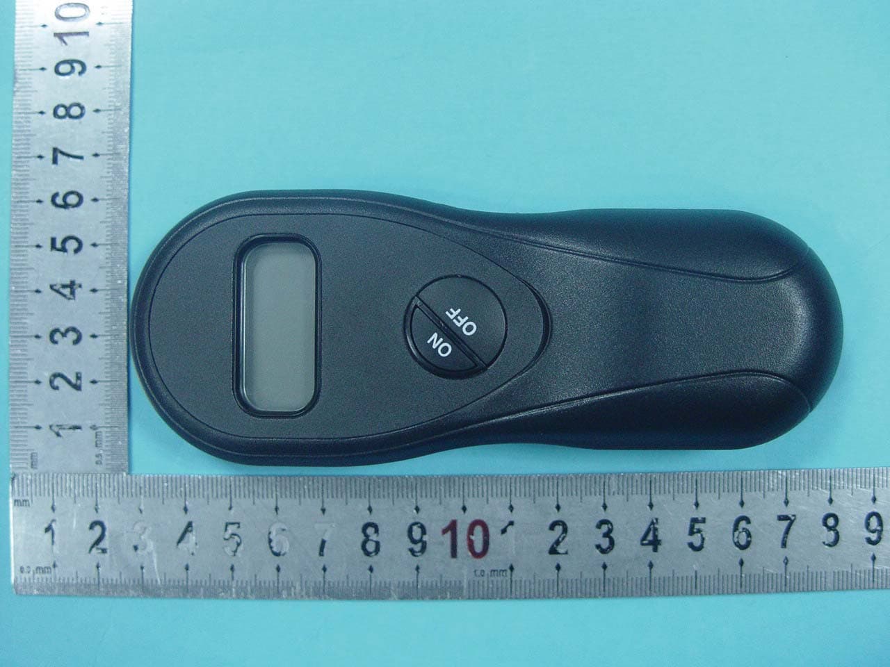
EPK504Acumen FDC 504 Tx Only
Acumen Technologies Ltd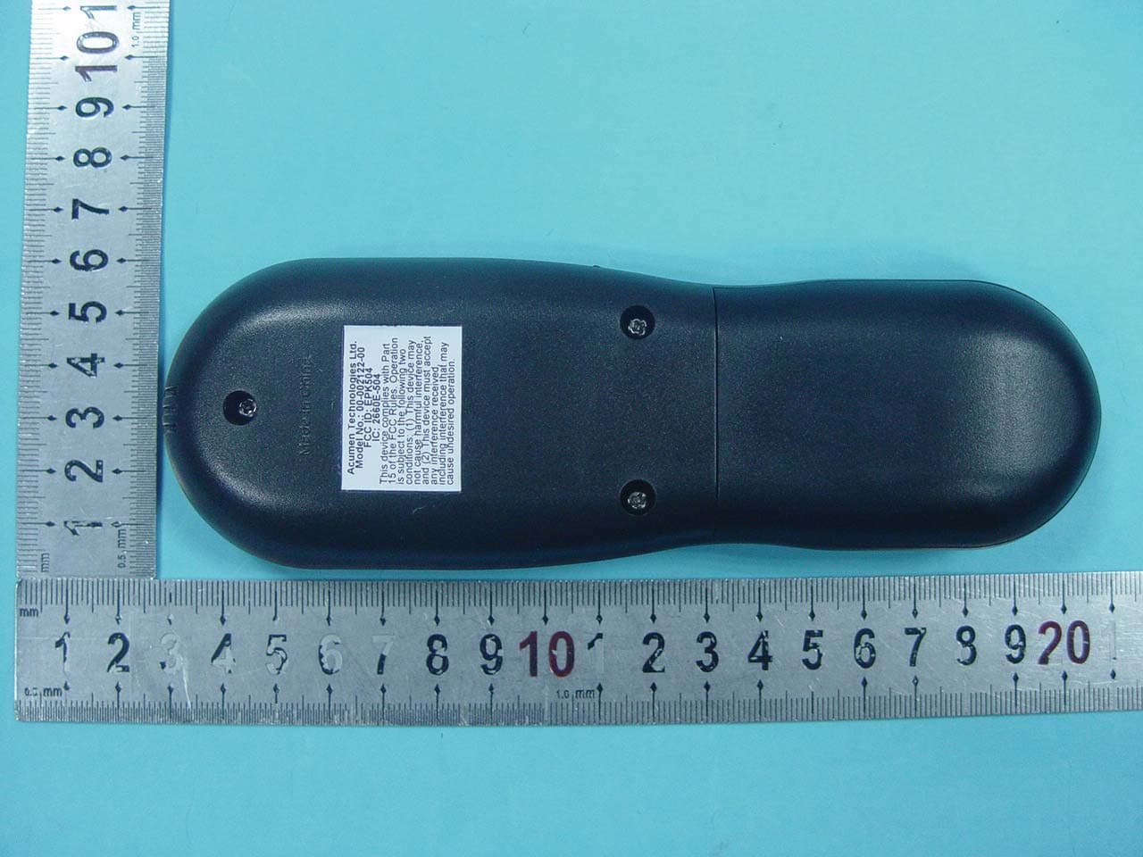
Click to zoom
Application Details
- Equipment Class
- DSC - Part 15 Security/Remote Control Transmitter
- Date of Grant
- Dec 02, 2010
- Application Purpose
- Original Equipment
- Date of Application
- Dec 02, 2010
- Equipment Note
- Acumen FDC 504 Tx Only
- Frequency Range
- 350.00000000 - 350.00000000
- Company
- Acumen Technologies Ltd
- Country
- China
Documents & Files
Document Text
Text extracted from the exhibit documents filed with the FCC. Open a document above to read the original.
Users Manual
Page 1 of 4 INSTALL BATTERIES INTO RECEIVER: INSTALL BATTERIES INTO TRANSMITTER: Replace Batteries At Least Every 6 Months. WARNING:THE REMOTE TRANSMITTER WILL AUTOMATICALLY SWITCH OFF THE FIREPLACE WHEN THE BATTERIES IN THE REMOTE TRANSMITTER ARE LOW. RECEIVER OPERATION: Fireplace Remote Control Operating Instructions For The Homeowner The Model L Remote Control is designed for use with decorative gas fireplace and wall heaters using a Millivolt gas valve. BEFORE YOU BEGIN: WarningThe pilot flame must be lit, with the gas control valve turned to "ON", for the remote to work correctly. Read all of the safety precautions in the owner's manual included with your fireplace before using this remote control.The thermostat is not intended for unattended use. INSTALLING FRESH BATTERIES: Note: It is not necessary to re-set your private code when Installing Fresh Batteries. The fireplace MUST be OFF before replacing transmitter batteries. Acumen Model L AA Alkaline Batteries. Press and Release PRESS TO OPEN PRESS TO OPEN FIREPLACE REMOTE PRESS TO OPEN OFF REMOTE BAT.LOW Fireplace Controlled by Remote Fireplace Off Fireplace On Low Battery Indicator OFF REMOTE ON BAT.LOW PRESS TO OPEN OFF REMOTE ON BAT.LOW PRESS TO OPEN OFF REMOTE ON BAT.LOW PRESS TO OPEN Page 2 of 4 SETTING THE CLOCK / TEMPERATURE MODE. See Figure 2 Press and hold the Clock button for approximately 2 seconds until the hour display starts to flash (Remote must be in Auto mode). Use the Up and Down buttons to set the hour. Pressing the Clock button again will cause the minute display to flash. Use the Up and Down buttons to set the minutes. Press the Clock button a third time to activate the °F or °C display. Use the Up and Down buttons to adjust for the desired modes. To exit the setting mode, press the Clock button. TRANSMITTER OPERATION: WARNING: IT TAKES SOME TIME FOR THE RECEIVER TO RESPOND TO THE TRANSMITTER. DO NOT PRESS THE BUTTONS MORE THAN ONCE WITH 2 SECONDS FOR CORRECT OPERATION. Fahrenheit or Celsius display CLOCK button TIMER button "UP" and "DOWN" Buttons PM ROOM TEMP SET TEMP TIMER C F F C Auto Mode. See Figure 3 Auto mode works like a thermostat, turning the heater on and off to meet the desired temperature. TIMER OPERATION. See Figure 5 1. You can set the timer to the length of time you want the fireplace to operate (1 to 120 minutes). 2. Press the TIMER button once. The Timer display "---" will blink. 3. Press the Up and Down buttons to set the timer. The LCD will display the time chosen. 4. The timer setting can be canceled at any time by pressing and holding the "TIMER" button. 5. Press Manual or the Auto On/Off button to turn on the fireplace. 6. The fireplace will turn off at the end of the timer setting. Manual Mode. See Figure 4 1. Press the Manual On/Off button once to light the fireplace. Push the button again to turn it off. 2. In Manual mode the Remote Transmitter will not turn the fireplace off/on even if the room temperature exceeds the target temperature. CAUTION: THE REMOTE RECEIVER WILL AUTOMATICALLY TURN OFF THE FIREPLACE AFTER SIX HOURS OF UNINTERRUPTED OPERATION. PRESS AUTO ON/OFF BUTTON ON THE REMOTE TRANSMITTER TO RESET THE REMOTE CONTROL, THEN PRESS AUTO ON/OFF BUTTON AGAIN TO RESUME OPERATION. 1. Press the "TIMER" button the "---" will start to flash. 2. Use the "UP" and "DOWN" buttons to set the Time. 3. Press Manual or Auto On/Off buttons to start the timer. ROOM TEMP SET TEMP TIMER C F F C MANUAL button AUTO ON/OFF button PM ROOM TEMP SET TEMP TIMER C F F C Fig 2 Fig 4 Fig 5 ROOM TEMP SET TEMP TIMER C F F C Adjust set Temperature Thermostatic Control PM Page 3 of 4 PM ROOM TEMP *Child-Proof* SET TEMP TIMER C F F C PM ROOM TEMP *Child-Proof* SET TEMP TIMER C F F C To unlock Child-Proof, press. UP DOWN DOWN UP DOWN Child-Proof off Child-Proof on The Child-Proof switch disables the buttons on the front of the Remote. Thermostat and timer functions continue to operate. Child-Proof Feature, SeeFigure 6 C-P C-P C-P The words "Child-Proof" appear here when Child- Proof feature is turned on. The words "Child-Proof" will disappear from the LCD. The "Child-Proof " will disappear from the LCD. SET PRIVATE CODE. SeeFigure 7 Fig 6 ROOM TEMP SET TEMP TIMER C F F C PM 1. Remove the cover at the back of the Remote Transmitter to expose the CHILD-PROOF switch. 2. Slide the CHILD-PROOF switch to position marked C/P to activate the CHILD-PROOF function "*Child- Proof*" will appear on the LCD. 3. In CHILD-PROOF mode the Remote Transmitter will not operate the Remote Receiver until the "child-Proof" code is used or the switch is returned to the other position. 4. Press the Up and Down buttons in the following sequence: Up-Down-Down-Up-Down within 2 seconds button function will be temporarily restored, "*Child-Proof*" will disappear from the LCD. 5. If no button is pressed within 2 minutes, the Remote Transmitter will return to Child-Proof function and "*Child-Proof*" will reappear on the LCD until the Child-Proof switch is slid back to the other position or the up-down sequence is repeated. A privacy code can be set to prevent accidental operation of the fireplace by other nearby transmitters. 1.Remove the cover on the back of the Remote Transmitter to expose the code switches. Slide the code switches to your choice of On or Off positions. Factory setting is all "off". 2. Make sure the slide switch on the Remote Receiver is at Off position. 3. Take the Remote Transmitter close to the fireplace or the Remote Receiver (less than 2-10 feet from the fireplace or Remote Receiver is recommended.) 4. Slide the slide switch on the Remote Receiver to REMOTE position. 5. Install fresh AAA alkaline batteries into the Remote Transmitter. 6. Press any button on the Remote Transmitter, the Remote Receiver will produce a "beep" sound when it receives the code from the Remote Transmitter. 7. If you do not hear a "beep" sound from the Remote Receiver, remove the batteries from the Remote Transmitter and slide the slide switch…
Text truncated - open the document above for the full version.
Block Diagram
Applicant: Acumen Technologies Ltd. FCC ID: EPK504 Block Diagram Battery 3V Stabilivolt Code Switch Child-Proof Switch MCU LCD LCD Backlight Operation Button X3 Crystal Oscillators 350MHz LC Resonance Transmitting 350MHz Power Amplifier Tube Probe for Ambient temperature X2 Crystal Oscillators 4.19MHz X1 Crystal Oscillators 32768Hz
ID Label/Location Info
FCC Certification label Sample
ID Label/Location Info
FCC Certification Label Location Sample Label location
Internal Photos
Antenna
Operational Description
Applicant: Acumen Technologies Ltd. FCC ID: EPK504 Operation Description In FDC504 Remote control, 350MHz transmitting frequency is adopted. MCU change the operational order to the signal of low frequency data string, then output. Next, Add this signal level to the both ends of 350MHz Crystal oscillator in order that the crystal oscillator could produce 350MHz high frequency wave of oscillations. High frequency wave as carrier signal to be amplified power,make the amplified carrier signal produce frequency resonance on LC return circuit, so as to obtain RF signal with enough power and emit. LCD mainly display TIME, TEMPERATURE and according function status for easy operation. And the LCD backlight can only be lighten by operating function, it’s for see clearly when operation in the dark. Temperature Probe is to detect ambient temperature then display the data on LCD. Child-Proof (C-P) switch is to prevent terminating machine from appearing abnormal by child faulty operation. Code switch is to request the user to set coding number to ensure that the each terminating machine won’t be influenced by neighboring user operate remote control in the same time. Auto Mode works like a thermostat, turning the heater on and off to meet the desired temperature. Antenna is formed by a copper trace on the PCB. Common grounding on PCB is not connected to real external ground. Power supply is DC 4.5V by three “AAA” batteries.
Schematics
0409130201c.sch-1 - Tue Oct 19 14:13:28 2010 32768HZ
Test Report
Page 1 of 31 FCC ID: EPK504 ACCURATE TECHNOLOGY CO., LTD REPORT NO. ATE20102185 APPLICATION CERTIFICATION On Behalf of Acumen Technologies Ltd. Acumen FDC 504 Tx ONLY Model No.: 00-002122-00 FCC ID: EPK504 Prepared for : Acumen Technologies Ltd. Address : Guang Zhou, She Jiang Town, Mei County, Guang Province, Mei Zhou City, China Prepared by : ACCURATE TECHNOLOGY CO., LTD Address : F1, Bldg. A, Changyuan New Material Port, Keyuan Rd. Science & Industry Park, Nanshan, Shenzhen, Guangdong P.R. China Tel: (0755) 26503290 Fax: (0755) 26503396 Report Number : ATE20102185 Date of Test : October 22-23, 2010 Date of Report : October 28, 2010 Page 2 of 31 FCC ID: EPK504 ACCURATE TECHNOLOGY CO., LTD REPORT NO. ATE20102185 TABLE OF CONTENTS Description Page Test Report Certification 1. GENERAL INFORMATION.......................................................................................................... 4 1.1. Description of Device (EUT)....................................................................................................................4 1.2. Description of Test Facility......................................................................................................................5 1.3. Measurement Uncertainty.........................................................................................................................5 2. MEASURING DEVICE AND TEST EQUIPMENT..................................................................... 6 3. SUMMARY OF TEST RESULTS................................................................................................... 7 4. THE FIELD STRENGTH OF RADIATION EMISSION............................................................ 8 4.1. Block Diagram of Test Setup....................................................................................................................8 4.2. The Field Strength of Radiation Emission Measurement Limits..............................................................9 4.3. Configuration of EUT on Measurement...................................................................................................9 4.4. Operating Condition of EUT....................................................................................................................9 4.5. Test Procedure........................................................................................................................................10 4.6. The Field Strength of Radiation Emission Measurement Results..........................................................11 5. 20DB OCCUPIED BANDWIDTH................................................................................................ 12 5.1. Block Diagram of Test Setup..................................................................................................................12 5.2. The Bandwidth of Emission Limit According To FCC Part 15 Section 15.231(c)................................12 5.3. EUT Configuration on Measurement.....................................................................................................13 5.4. Operating Condition of EUT..................................................................................................................13 5.5. Test Procedure........................................................................................................................................13 5.6. Measurement Result...............................................................................................................................14 6. RELEASE TIME MEASUREMENT............................................................................................ 15 6.1. Block Diagram of Test Setup..................................................................................................................15 6.2. Release Time Measurement According To FCC Part 15 Section 15.231(a)..........................................15 6.3. EUT Configuration on Measurement.....................................................................................................16 6.4. Operating Condition of EUT..................................................................................................................16 6.5. Test Procedure........................................................................................................................................16 6.6. Measurement Result...............................................................................................................................17 7. AVERAGE FACTOR MEASUREMENT.................................................................................... 18 7.1. Block Diagram of Test Setup..................................................................................................................18 7.2. Average factor Measurement according to ANSI 63.4: 2003.................................................................18 7.3. EUT Configuration on Measurement.....................................................................................................19 7.4. Operating Condition of EUT..................................................................................................................19 7.5. Test Procedure........................................................................................................................................19 7.6. Measurement Result...............................................................................................................................20 APPENDIX I ( TEST CURVES) (10 pages) Page 3 of 31 Test Report Certification Applicant : Acumen Technologies Ltd. Manufacturer : Acumen Technologies Ltd. EUT Description : Acumen FDC 504 Tx ONLY (A) MODEL NO.: 00-002122-00 (B) SERIAL NO.: N/A (C) POWER SUPPLY: 4.5V DC (“AAA” batteries 3) Measurement Procedure Used: FCC Rules and Regulations Part 15 Subpart C Section 15.231 ANSI 63.4: 2003 The device described above is tested by ACCURATE TECHNOLOGY CO., LTD to…
Text truncated - open the document above for the full version.
Test Setup Photos
Radiated emissions test < 1GHz Radiated emissions test > 1GHz
Contact Information
Applicant
KY Sham
Test Firm
Accurate Technology Co., Ltd.Sean Liu
Technical Specifications
| # | Rule Parts | Frequency Range | Power Output |
|---|---|---|---|
| 1 | 15.231 | 350 MHz - 350 MHz | - |
Other Applications from Acumen Technologies Ltd
EPK502
Dec 02, 2010Acumen FDC 502 Tx Only
Equipment Class
DSC - Part 15 Security/Remote Control Transmitter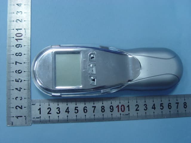
EPKEON0304
Nov 19, 2007EON 03/04
Equipment Class
DSC - Part 15 Security/Remote Control Transmitter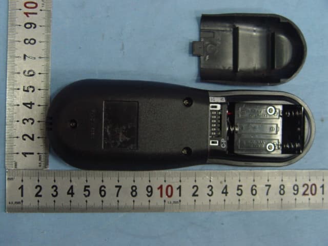
EPK001105A
Oct 23, 2006Johnson Gas RF Model H Version
Equipment Class
DSC - Part 15 Security/Remote Control Transmitter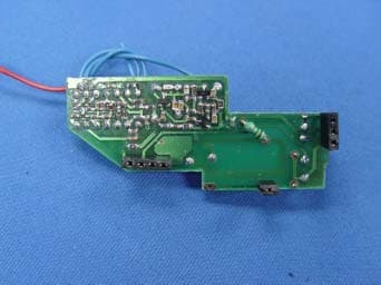
EPK001106A
Sep 26, 2006Fireplace Remote Control
Equipment Class
DSC - Part 15 Security/Remote Control Transmitter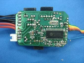
EPK063601A
Sep 25, 2006Fireplace Remote Control
Equipment Class
DSR - Part 15 Remote Control/Security Device Transceiver