EPKEON0304EON 03/04
Acumen Technologies Ltd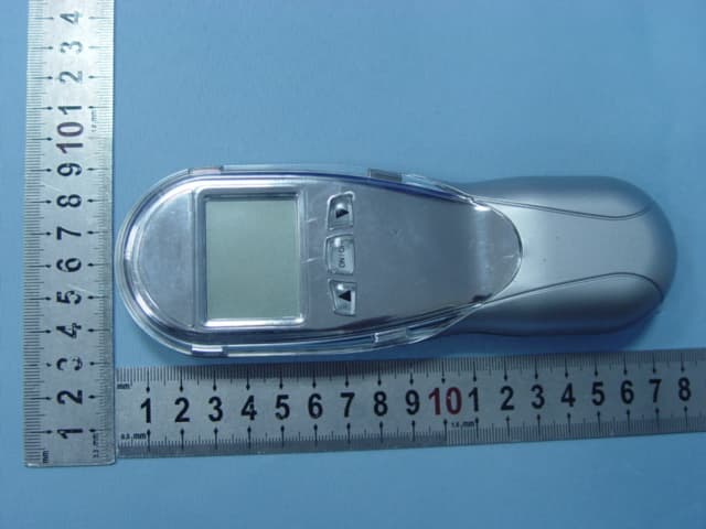
Click to zoom
Application Details
- Equipment Class
- DSC - Part 15 Security/Remote Control Transmitter
- Date of Grant
- Nov 19, 2007
- Application Purpose
- Original Equipment
- Date of Application
- Nov 19, 2007
- Equipment Note
- EON 03/04
- Frequency Range
- 350.00000000 - 350.00000000
- Company
- Acumen Technologies Ltd
- Country
- China
Documents & Files
Document Text
Text extracted from the exhibit documents filed with the FCC. Open a document above to read the original.
Users Manual
Acumen Model EON03/04 Fireplace Remote Control Installation and Operation Instructions The Acumen Model EON03/04 Remote Control is designed for use with decorative gas fireplace and wall heaters using SIT 852 Nova gas valve and digital flame control millivolt valve. The Model EON03/04 Transmitter is an three/eight-button hand held transmitter, which turn the gas on/off or as a thermostat, adjust the flame height, The display of the transmitter shows the clock, current room temperature, target temperature, timer setting, on/off status and low battery indicator. 1.0 Operation Instructions The Model EON03/04 Remote Control has 1or6 operating modes. They are: Manual or Manual, Auto, Timer, Flame Adjustment and Transmitter Location Function. You can only operate the Flame Adjustment in Manual or Auto Modes. Use the Up and Down buttons to set the target temperature between 45 o F and 90 o F, or 8°C and 32°C. 1.0.1. Manual Mode Press the Manual On/Off button once to light the fireplace. Push the button again to turn it off. In Manual mode the Remote Transmitter will not turn the fireplace off even if the room temperature exceeds the target temperature. 1.0.2. Auto Mode(EON04 olny) 1. Set the desired target temperature. 2. Press the Auto On/Off button once to activate the Auto mode. In Auto Mode the Remote Transmitter will automatically turn on the fireplace when the room temperature is below the target temperature and turn off the fireplace when the room temperature is above the target temperature. 3. Press Auto On/Off button or Manual On/Off buttons to turn off the fireplace (if it is already on) and exit Auto Mode. 1.0.3. Timer Mode(EON04 olny) 1. You can set the timer to the length of time you want the fireplace to operate (1 to 120 minutes). 2. Press the ”TMER” button once. The Timer display “----“ will blink. 3. Press the Up and Down buttons to set the timer. The LCD will display the time chosen. 4. The timer setting can be cancelled at any time by press and hold the ”TIMER” button. 5. Press Manual or Auto On/Off button to turn on the fireplace. 6. The fireplace will turn off at the end of the timer setting. 1.0.4. Flame Adjustment 1. In Manual and Auto modes you can adjust the flame height of the fireplace. 2. Press the Flame button and use the Up and down arrow to adjust the flame height to 1, 2, 3 and 4. 1.0.5. Child-Proof Function 1. Remove the cover at the back of the Remote Transmitter to expose the CHILD-PROOF switch. Slide the CHILD-PROOF switch to position marked C/P to activate the CHILD-PROOF function “*Child-Proof *” will appear on the LCD. 2. In CHILD-PROOF the Remote Transmitter will not operate the Remote Receiver until the “child-proof” code is used or the switch is returned to the other position. 3. Press the Up and Down buttons in the following sequence, Up-Down-Down-Up-Down, within 2 seconds button function will be temporarily restored, “*Child-Proof*” will disappear from the LCD. 4. If no button is pressed within 2 minutes, the Remote Transmitter will return to Child-Proof function and “*Child-Proof*” will reappear on the LCD until the Child-Proof switch is slide back to the other position. 1.0.6. Settings 1. Press and hold clock button for about 2 seconds. 2. The hour display will flash. Use the Up and Down buttons to set the hour. 3. Pres the clock button again and the minute display will flash. Use the Up and Down buttons to set the minutes. 4. Press the clock button again and the °F or °C display will flash. Use the Up and Down button to select the Remote Transmitter to display temperature in °F or °C. 5. Press the clock button again to exit setting. 1.0.7. Batteries 1. The Remote Transmitter uses 3 AAA-size batteries. Replace these batteries at least every 6 months or when the Low battery indicator on the LCD is on. 2. After you take out the batteries, wait for at least 1 minute before putting fresh batteries into the Remote Transmitter. 3. Use fresh alkaline batteries only. 1.0.8. Transmitter Location Function Acumen’s Remove Control’s location function can help user to find the Remove Transmitter easily. Turn on the Transmitter Location function by pressing the “Tx Locator” button on the Remove Receiver, and then transmitter will beep continuously (Two short and one long beep), Press any button on the Remove Transmitter to turn it off. 1.0.9. Receiver Low Battery Warning Low Battery Indicator on the Remove Receiver automatically measures low battery power from the Remove Receiver. When the battery runs low and needs to be replaced, the indicator will blink in red and the LCD of the transmitter will display. Replace the batteries as soon as practical. 2.0 IMPORTANT SAFETY FEATURE You can set a private code into your system to prevent accidental operation by another transmitter nearby. 2.1 Coding Instructions 1. Remove the cover on the back of the Remote Transmitter to expose the code switches. Slide the code switches to you choice of ON or OFF positions. FACTORY SETTING IS ALL ”OFF”. 2. Remove power from the Remote Receiver by unplugging the power cord or power off at the circuit breaker. 3. Take the Remote Transmitter close to the fireplace or the Remote Receiver (less than 2-10 foot from the fireplace or Remote Receiver is recommended.) 4. Powering-up the Remote Receiver. 5. Install fresh AAA alkaline batteries into the Remote Transmitter. 6. Press a button on the Remote Transmitter. The Remote Receiver will produce a ‘beep’ sound when it receives the code from the Remote Transmitter. 7. If you do not hear a ‘beep’ sound from the Remote Receiver, removes batteries from the Remote Transmitter and power from the Remote Receiver. Wait for 1 minute and repeat step 3 to 6. 8. The system is now ready to operate.
Block Diagram
Remote EON03/04 Transmitter Block Diagram 6 Address switch LCD Micro-controller (Clock=32768HZ,Crystal oscillator:4.19MHZ ceramic Resonator oscillator) Key RF oscillator L.C. oscillator Frequency =350Mhz RF oscillator L.C. oscillator Frequency =350Mhz(Rx) Buzzer
ID Label/Location Info
IC ID : 2887A-EON0304 FCC ID : EPKEON0304 FCC ID : EPKEON0304 IC ID : 2887A-EON0304 EON-03 EON-04 ACUMEN MODEL NO. : FTX-S3 MODEL NO. : FTX-S4 ACUMEN
Operational Description
Principle of Operation Operation Frequency: 350MHz Modulation Type: ASK The micro-controller (U1) on the Remote Transmitter reads the resistance of the temperature sensor (TH1) every 16 second. It then converts the resistance reading into temperature reading and display the temperature on the LCD. When the user press the auto button on the Remote Transmitter, the micro-controller will compare the preset temperature with the room temperature. If the room temperature is above/below the preset temperature, it will send a series of on/off code words to turn on/off the RF oscillator which in turn will transmit an ASK RF signal to the Remote Receiver. When the user press the manual on the Remote Transmitter, the micro- controller on the Remote Transmitter will send a series of on code words (if the Remote Transmitter is at off state) or off code words (if the Remote Transmitter is at on state) to the RF oscillator. The RF oscillator will in turn transmit an ASK RF signal to the Remote Receiver. When the user press the flame or fan buttons on the Remote Transmitter, the micro-controller will send a series of code words to the RF oscillator. The RF oscillator will turn ASK RF signal to the Remote receiver. All timing on the Remote Transmitter is derived from 32768 Hz Crystal- Oscillator and 4.19 MHz Ceramic Resonator Oscillator.
Schematics
EON03/04
Test Report
Page 1 of 37 ACCURATE TECHNOLOGY CO. LTD REPORT NO. ATE20072541 APPLICATION CERTIFICATION On Behalf of South East Asia Resources Ltd. EON 03/04 Model No.: FTX-S3, FTX-S4 FCC ID: EPKEON0304 IC ID: 2887A-EON0304 Prepared for : South East Asia Resources Ltd. Address : 1902-03, Kwong Sang Center, 151-153 Hoi Bun Road Kwun Tong, Hong Kong Prepared by : ACCURATE TECHNOLOGY CO. LTD Address : F1, Bldg. A, Changyuan New Material Port, Keyuan Rd. Science & Industry Park, Nanshan, Shenzhen, Guangdong P.R. China Tel: (0755) 26503290 Fax: (0755) 26503396 Report Number : ATE20072541 Date of Test : October 29, 2007 Date of Report : October 31, 2007 Page 2 of 37 ACCURATE TECHNOLOGY CO. LTD REPORT NO. ATE20072541 TABLE OF CONTENTS Description Page Test Report Certification 1. GENERAL INFORMATION .......................................................................................................... 4 1.1. Description of Device (EUT)....................................................................................................................4 1.2. Description of Test Facility ......................................................................................................................4 1.3. Measurement Uncertainty.........................................................................................................................4 2. MEASURING DEVICE AND TEST EQUIPMENT ..................................................................... 5 3. THE FIELD STRENGTH OF RADIATED EMISSION .............................................................. 6 3.1. Block Diagram of Test Setup....................................................................................................................6 3.2. The Field Strength of Radiated Emission Measurement Limits ...............................................................6 3.3. Configuration of EUT on Measurement ...................................................................................................7 3.4. Operating Condition of EUT ....................................................................................................................7 3.5. Test Procedure ..........................................................................................................................................7 3.6. The Field Strength of Radiation Emission Measurement Results ............................................................9 4. 20DB OCCUPIED BANDWIDTH ................................................................................................ 11 4.1. Block Diagram of Test Setup..................................................................................................................11 4.2. The Bandwidth of Emission Limit According To FCC Part 15 Section 15.231(c) ................................11 4.3. EUT Configuration on Measurement .....................................................................................................12 4.4. Operating Condition of EUT ..................................................................................................................12 4.5. Test Procedure ........................................................................................................................................12 4.6. Measurement Result ...............................................................................................................................13 5. 99% OCCUPIED BANDWIDTH .................................................................................................. 14 5.1. Block Diagram of Test Setup..................................................................................................................14 5.2. The Bandwidth of Emission Limit According To RSS-210 A1.1.3 .......................................................14 5.3. EUT Configuration on Measurement .....................................................................................................15 5.4. Operating Condition of EUT ..................................................................................................................15 5.5. Test Procedure ........................................................................................................................................15 5.6. Measurement Result ...............................................................................................................................16 6. RELEASE TIME MEASUREMENT............................................................................................ 17 6.1. Block Diagram of Test Setup..................................................................................................................17 6.2. Release Time Measurement According To FCC Part 15 Section 15.231(a)& RSS-210 A1.1.1 ............17 6.3. EUT Configuration on Measurement .....................................................................................................18 6.4. Operating Condition of EUT ..................................................................................................................18 6.5. Test Procedure ........................................................................................................................................18 6.6. Measurement Result ...............................................................................................................................19 7. AVERAGE FACTOR MEASUREMENT .................................................................................... 20 7.1. Block Diagram of Test Setup..................................................................................................................20 7.2. Average factor Measurement according to ANSI 63.4: 2003.................................................................20 7.3. EUT Configuration on Measurement .....................................................................................................21 7.4. Operating Condition of EUT ....................…
Text truncated - open the document above for the full version.
Contact Information
Applicant
KY Sham
Test Firm
Accurate Technology Co., Ltd.Sean Liu
Technical Specifications
| # | Rule Parts | Frequency Range | Power Output |
|---|---|---|---|
| 1 | 15.231 | 350 MHz - 350 MHz | - |
Other Applications from Acumen Technologies Ltd
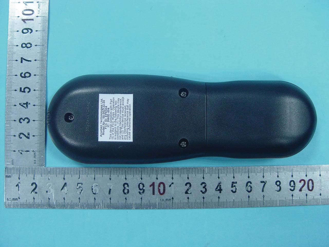
EPK504
Dec 02, 2010Acumen FDC 504 Tx Only
Equipment Class
DSC - Part 15 Security/Remote Control Transmitter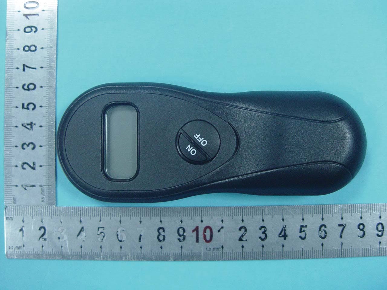
EPK502
Dec 02, 2010Acumen FDC 502 Tx Only
Equipment Class
DSC - Part 15 Security/Remote Control Transmitter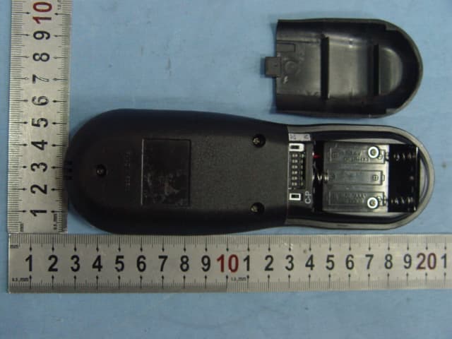
EPK001105A
Oct 23, 2006Johnson Gas RF Model H Version
Equipment Class
DSC - Part 15 Security/Remote Control Transmitter
EPK001106A
Sep 26, 2006Fireplace Remote Control
Equipment Class
DSC - Part 15 Security/Remote Control Transmitter
EPK063601A
Sep 25, 2006Fireplace Remote Control
Equipment Class
DSR - Part 15 Remote Control/Security Device Transceiver