EWBF9S93619 Inch Color Digital Monitor
Orion Electric Co Ltd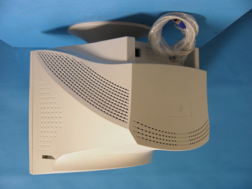
Click to zoom
Application Details
- Equipment Class
- JBP - Part 15 Class B Computing Device Peripheral
- Date of Grant
- Sep 05, 2001
- Application Purpose
- Original Equipment
- Date of Application
- Sep 05, 2001
- Equipment Note
- 19 Inch Color Digital Monitor
- Company
- Orion Electric Co Ltd
- Country
- South Korea
Documents & Files
Document Text
Text extracted from the exhibit documents filed with the FCC. Open a document above to read the original.
Users Manual
USER’S MANUAL MODEL No.: F9S936 BEFORE USING THIS COLOR MONITOR, READ AND OBSERVE ALL OF THIS USER’S MANUAL 19” DIGITAL COLOR MONITOR 1 INSTRUCTION MANUAL CONTENTS SAFETY INSTRUCTION2 CAUTIONS4 FCC RF INTERFERENCE STATEMENT5 INSTALLATION6 RESOLUTION7 CONTROLS AND FUNCTIONS8 REAR VIEW13 POWER MANAGEMENT14 SPECIFICATIONS15 TROUBLE SHOOTING GUIDE16 This Monitor was Manufactured by ISO 9001 Certified Factory INSTRUCTION MANUAL2 SAFETY INSTRUCTION 1. Read all of these instructions. 2. Save these instructions for later use. 3. Follow all warnings and instructions marked on the product. 4. Unplug this product from the wall outlet before cleaning. Do not use liquid cleaners or aerosol cleaners. Use a dry cloth for cleaning. 5. Do not use this product near water. 6. Do not place this product on an unstable cart, stand or table. The product may fall, causing serious damage to the product. 7. Slots and openings in the cabinet and the back or bottom are provided for ventilation: to ensure reliable operation of the product and to protect it from overheating these openings must not be blocked by placing the product on a bed, sofa, rug or other similar surface. This product should never be placed near or over a heat register. This product should not be placed in a built-in installation unless proper ventilation is provided. 8. This product should be operated from the type of power source indicated on the marking label. If you are not sure of the type of power available consult your dealer or local power company. 9. This product is equipped with a 3 wire grounding type plug having a third(grounding) pin. This is a safety feature. If you are unable to insert the plug into the outlet, contact your electrician to replace your obsolete outlet. Do not defeat the purpose of the grounding-type plug. 10. Do not allow anything to rest on the power cord. Do not locate this product where persons will walk on the cord. 11. If an extension cord is used with this product, make sure that the total of the ampere ratings on the products plugged into the extension cord do not exceed the extension cord ampere rating. Also, make sure that the total of all products plugged into the wall outlet does not exceed 10 amperes. 12. Never push objects of any kind into this product through cabinet slots as they may touch dangerous voltage points or short out parts that could result in a risk of fire or electric shock. Never spill any kind of liquid on the product. 3 INSTRUCTION MANUAL SAFETY INSTRUCTION 13. Do not attempt to service this product yourself, as opening or removing covers may expose you to dangerous voltage points or other risks. Refer all servicing to service personnel. 14. Unplug this product from the wall outlet and refer servicing to qualified service personnel under the following conditions. A. When the power cord or plug is damaged or frayed. B. If liquid has been spilled into the product. C. If the product has been exposed to rain or water. D. If the Product does not operate normally when the operating instructions are followed. Adjust only those controls that are covered by the operating instructions since improper adjustment of other controls may result in damage and will often require extensive work by a qualified technician to restore normal operation. E. If the product has been dropped or the cabinet has been damaged. F. If the product exhibits a distinct change in performance, indicating a need for service. CC CC AA AA UU UU TT TT II II OO OO NN NN The power supply cord is used as the main disconnect device, ensure that the socket-outlet is located/installed near the equipment and is easily accessible. AA AA TT TT TT TT EE EE NN NN TT TT II II OO OO NN NN Le cordon d`alimentation est utillsé comme interrupteur général. La prise de courant doit être située ou installée à proximité du matériel et être facile d`accès CAUTION TO SERVICE PERSONNEL POWER SUPPLY CORD IS USED AS MAIN POWER DISCONNECT DEVICE IN THIS PRODUCT. UNPLUG THIS PRODUCT FROM THE WALL OUTLET BEFORE REMOVING THE BACK COVER AND SERVICING EMISSION CHARACTERISTICS TESTED BY SEMKO THIS PRODUCT HAS BEEN TESTED AND HAS SHOWN COMPLIANCE WITH THE NATIONAL SPECIFICATIONS SUCH AS SWEDISH MPR 1990.10.(MPR) INSTRUCTION MANUAL 4 CAUTIONS NEVER REMOVE THE BACK COVER NEVER REMOVE THE BACK COVER Removal of the back cover should be carried out only by qualified personnel. This display monitor contains high voltage inside. DO NOT USE IN HOSTILE ENVIRONMENTS DO NOT USE IN HOSTILE ENVIRONMENTS To prevent shock or fire hazard. Do not expose the unit to rain or moisture. This unit is designed to be used in the office or home. Do not subject the unit to vibrations, dust of corrosive gases. KEEP IN A WELL VENTILATED PLACE KEEP IN A WELL VENTILATED PLACE Ventilation holes are provided on the cabinet to prevent the temperature from rising. Do not cover the unit or place anything on the top of unit. Ventilation holes are provided also on the bottom of the cabinet. AVOID HEAT AVOID HEAT Avoid placing the unit in direct sunshine or near a heating appliance. BE CAREFUL OF MAGNETIC FIELDS BE CAREFUL OF MAGNETIC FIELDS Do not place a magnet, speaker system, floppy disc drive or anything which will generate magnetism near the unit, A magnetic field may cause blurred colors or distortion of the displayed pattern. TO ELIMINATE EYE FATIGUE TO ELIMINATE EYE FATIGUE Do not use the unit against a bright back ground and where sunlight or other light sources will shine directly on the monitor. BE CAREFUL OF HEAVY OBJECT BE CAREFUL OF HEAVY OBJECT Neither the monitor itself nor any other heavy object should rest on the power cord. Damage to a power cord can cause fire or electrical shock. 5 INSTRUCTION MANUAL FCC RF INTERFERENCE STATEMENT NN NN OO OO TT TT EE EE :: :: This equipment has been tested and found to comply with the limits for a Class B digital device, pursuant to Part 15 of the FCC Rules. These limits are designed to provide reasonable protection against harmful interferen…
Text truncated - open the document above for the full version.
Cover Letter(s)
Orion Electric Co.,Ltd 257 Gongdan-Dong, Gumi-City, Kyunbuk, Korea (730-030) Tel: 82-54-467-5921 Fax: 82-54-463-0243 January 04, 2001 Underwriters Laboratories Inc. 333 Pfingston Road. Northbrook, Illinois 60062-2096 U.S.A. To whom it may concern: We, the undersigned, hereby authorize IST Co.,Ltd. To act an our behalf in all matters relating to applications for equipment authorization, including the signing of all documents relating to these matters. Any and all acts carried out by IST Co.,Ltd., on our behalf shall have the same effect as acts of our own. We also hereby certify that no party to this application is subject to denial of benefits, including FCC benefits, pursuant to section 5301 of the Anti-Drug Abuse Act of 1998. 21 U.S.C. 862. Sincerely, Charles H. Hur Assistant Manager Monitor development team Orion Electric Co.,Ltd
ID Label/Location Info
ID Label Location Information
ID Label/Location Info
Label Sample
Operational Description
Operational Description of 9S936 & F9S936 1. Power supply circuit 1) AC Inlet(EMI filter) The AC power is supplied to the EMI filtering circuit which consists of an X-Cap and two Y-Caps. This filter reduces the conducted noise through power line. 2) Bridge Rectifier circuit This circuit converts AC input voltage into DC voltage by rectifying through bridge diode(Location D850) and bulk capacitor(C802). 3) Output voltages The power supply circuit makes DC output voltages : 5V, 12V, 14.5V, 27V, 80V, 190V. 4) Power On/Off When the voltages of the Microprocessor pin #5 & #9 become high levels, Q823 & Q825 is turned on, and then the DC voltage is supplied to the boards and the state is power on. 2. Horizontal & Vertical Deflection circuit The H/V oscillation IC TDA9113 makes Horizontal drive pulse for Horizontal drive circuit and Vertical ramp pulse for Vertical driver(TDA8172). The Horizontal drive pulse frequency range is from 30KHz to 96KHz. Horizontal drive pulse is supplied to Horizontal drive tansistor(Q411). When the vertical sync is supplied to IC TDA9113 pin 2, vertical ramp pulse is made. The OSC IC TDA9113 is controlled by the I 2 C bus control of the microprocessor, and the 8bit I 2 C bus controls Geometric Distortion, Horizontal size, Phase and Vertical size, Position. 3. Microprocessor The microprocessor applied to this monitor is made by Motorola, and the name is WT62P1. The following is the major functions of the microprocessor. - H/V sync processing, Power on/off, DPMS function. - CS port output, Recall, Degaussing function. - OSD, H/V OSC, Video preamp IC control. The operating clock of the microprocessor is 12MHz, and has an I 2 C interface to control above ICs. 4. Horizontal drive and output part The output of Horizontal oscillator goes out of the pin #26 of IC TDA9113, and it is supplied to the base of Horizontal drive transistor Q411. A large amount of drive current necessary for horizontal output transistor Q405 is made by Q411 and T402(Horizontal drive transformer). Q405 is switched by pulse voltage provided by T402, and when On-time pulse is charged on the base of Q405, Q405 is turned on having collector current flow which increase linearly through horizontal deflection coil. At the moment of Off time, pulse is charged on the base of Q405, collector current stops increasing and it is turned off. All the above chain of actions becomes a cycle, and it goes on and on. And the high voltage of FBT is obtained from the same methods. The high voltage supports to CRT Anode. 5. Video Pre-Amp and OSD processing The Analog R.G.B signal is supplied from signal source, passed through capacitors C201, C202, C203 and inputted to the pin 5, 6, 7 of the Video Pre-Amp IC201(LM1267NA). Also, R, G, B OSD outputs are supplied to the pin 1, 2, 3 of IC201 coming out from the pin 10, 11, 12 of OSD generator IC501(MC141543).Fast-blanking signal of OSD is provided from the pin 13 of IC501 to the pin 4 of the IC201. Video Pre-Amp and OSD IC is controlled by I 2 C bus control of the microprocessor. 6. CRT output driver This video output circuit is consisted of the 3 channels video output amp IC. Also this device is integrated a internal CRT bias circuits and is supplied DC voltage +80V. The output voltage gain is obtained from the Pre-Amp output voltage level controlled by the microprocessor. The output voltage supplied to the CRT cathode is about 35V-40V and the output video bandwidth is maximum 100MHz.
Parts List/Tune Up Info
Part NameSPECLOCATION CORD, POWEREU/GRY/6FT/0.75230V TYPE C.D.T.(L.G)M46QEF903X01 C.D.T.(S.S)M46QCK761X123 COIL, DEGAUSSINGDC-1901D-COIL RES., CEMENT5W47, JR434,R454, CAP., ELECTROLYTICRSS 100U/250VC852, CAP., MET. POLYPRO.400V 684(378MKP)C802, CAP., MET. POLYPRO.275V/474C803,C815, CAP., ELECTROLYTICLHS 100U/450V(25X30)C804, CAP., MET. POLYPRO.932D684JES(MPU)C413, CAP., MET. POLYPRO932D804JESC410, CAP., POLYPROPYLENE400V 823JT(PFU)C489, CAP., POLYPROPYLENE933C532JPS(PSU/25MM)C406, CAP., POLYPROPYLENE250V 224JT(PFU/25MM)C411, CAP., POLYPROPYLENE400V 224JB(PFU)C417, SPARK GAPSPION 1.5KVG401, FUSE5ST 4A/250VF801, THERIMISTOR(NTC)TP8D13(DW)TH801, POSISTORPT11P63D090Q290TH802, NOISE FILTERIM-L03A2-PP801, I.C., SOCKET42PIN SDIPIC901, I.C., MCU(OTP)WT62P1IC101-S, I.C., H/V PROCESSTDA9113IC401, I.C.TLP621-D4TIC805, MOS.FETIRF 630A(NO CUT)/FQP630Q429, T.R.KTA1276YQ824, DIODERU3CD821, DIODERK39/LF-B1D826, DIODEMUR460D808, DIODE, BRIDGEG3SBA60D850, DIODERG4(LF-L1)D407,D416, DIODESB540D404, DIODESUF15GL-5703D822, RELAY(2A)DY3M-DC12VRY801, RELAYHR-CR3N23DC012RY801, TRANS., POWERSPT-926T801, TRANS.,D-FOCUSDFT-926T404, TRANS.,DUMMY FLYBACKDUF-936T403, TRANS., H-DRIVEHDT-936T402, TRANS., FLY BACKKJF-0105BT405, TRANS., TRIGGERTGT-936T803, COIL., PFCPFC-936T802, COIL LINE-FILTERLF-936L801, COIL, H-LINHLT-2R8MT401, WAFER5267-02A/YMW250-02P103, WAFER5268-03A/YMA250-03P106, WAFERMOLEX 5096-02C W7.92P804, WAFERSMW250-06P104, WAFER5268-04A/YMA250P106A, SIGNAL CABLEOMSC-1936A RELAYPCE-112D1H(OEG)RY401, I.C.KA7805/KIA7805P(AP)IC802, I.C.KA7812/KIA7812P(AP)IC803, F.E.TSTP6NC60FPQ804, MOS.FETIRF640AQ408, I.C.TDA 8172IC301, I.C.STR-F6654(A)IC801, T.R.A1659Q430, MOS.FETIRF 630A(NO CUT)/FQP630Q406,Q407, MOS.FETIRF640AQ415, MOS.FETIRF 644A(2)/FQP16N25 F.E.T2SK2545Q414, T.R.TT2062GMHQ405, DIODEDTV32F15D406, RES., FUSIBLE1/4W47, JR409, RES., FUSIBLE1W1, JR880,R881, RES., CARBON FILM1/6W1K, JR820, RES., CARBON FILM1/6W200K, JR969, RES., CARBON FILM1/6W220K, JR499, B O M RES., CARBON FILM1/6W4.7K, JR105, RES., CARBON FILM1/4W1, JR160, RES., CARBON FILM1/4W1.5, JR311, RES., CARBON FILM1/4W10, JR815, RES., CARBON FILM1/4W100, JR101,R113,R114,R123,R124,R127,R128,R129,R130,R429, RES., CARBON FILM1/4W100, JR447,R477,R496,R811,R997, RES., CARBON FILM1/4W1K, JR118,R119,R138,R407,R419,R437,R457,R491,R807,R854, RES., CARBON FILM1/4W1K, JR956,R974, RES., CARBON FILM1/4W10K, JR155,R161,R430,R442,R445,R466,R470,R476,R493,R972, RES., CARBON FILM1/4W100K, JR453, RES., CARBON FILM1/4W1M, JR817,R818,R975, RES., CARBON FILM1/4W110K, JR967, RES., CARBON FILM1/4W1.2K, JR489, RES., CARBON FILM1/4W130, JR436, RES., CARBON FILM1/4W13K, JR122, RES., CARBON FILM1/4W130K, JR858, RES., CARBON FILM1/4W150, JR819, RES., CARBON FILM1/4W15K, JR102,R103,R156,R162,R163,R449,R498,R814,R947, RES., CARBON FILM1/4W150K, JR117, RES., CARBON FILM1/4W1.5M, JR424,R428, RES., CARBON FILM1/4W180, JR111, RES., CARBON FILM1/4W1.8K, JR942, RES., CARBON FILM1/4W2.7, JR416, RES., CARBON FILM1/4W2K, JR435, RES., CARBON FILM1/4W220, JR857, RES., CARBON FILM1/4W22K, JR488, RES., CARBON FILM1/4W220K, JR853, RES., CARBON FILM1/4W2.4K, JR314, RES., CARBON FILM1/4W240K, JR964, RES., CARBON FILM1/4W2.7K, JR158, RES., CARBON FILM1/4W270K, JR440,R859,R971, RES., CARBON FILM1/4W330, JR810, RES., CARBON FILM1/4W3.3K, JR417,R444,R448,R456,R458,R485,R492,R959, RES., CARBON FILM1/4W33K, JR450,R467, RES., CARBON FILM1/4W330K, JR955, RES., CARBON FILM1/4W390, JR402, RES., CARBON FILM1/4W3.9K, JR443, RES., CARBON FILM1/4W3.9M, JR438, RES., CARBON FILM1/4W4.7, JR420,R812, RES., CARBON FILM1/4W47, JR441,R804, RES., CARBON FILM1/4W470, JR104,R142,R431, RES., CARBON FILM1/4W4.7K, JR107,R110,R115,R116,R131,R134,R140,R159,R426,R427, RES., CARBON FILM1/4W4.7K, JR471,R473,R474,R475,R487,R494,R495,R806, RES., CARBON FILM1/4W47K, JR816, RES., CARBON FILM1/4W51K, JR957, RES., CARBON FILM1/4W560, JR451, RES., CARBON FILM1/4W5.6K, JR112, RES., CARBON FILM1/4W56K, JR482, RES., CARBON FILM1/4W680, JR863, RES., CARBON FILM1/4W6.8K, JR497, RES., CARBON FILM1/4W68K, JR472, RES., CARBON FILM1/4W7.5K, JR401, RES., CARBON FILM1/4W820, JR855,R940, RES., CARBON FILM1/4W8.2K, JR126, RES., CARBON FILM1/4W82K, JR439, RES., CARBON FILM1/4W9.1K, JR137, RES., CARBON FILM1/2W1.2K, JR484, RES., METAL FILM1/2W180K, FR851, RES., CARBON FILM1/2W1K, J(SMALL)R821,R864, RES., CARBON FILM1/2W100K, J(SMALL)R996, RES., CARBON FILM1/2W1M, J(SMALL)R976,R981, RES., CARBON FILM1/2W1.5M, J(SMALL)R422,R459, RES., CARBON FILM1/2W18, J(SMALL)R970, RES., CARBON FILM1/2W2.2, J(SMALL)R803,R860, RES., CARBON FILM1/2W22, J(SMALL)R316, RES., CARBON FILM1/2W220, J(SMALL)R490, RES., CARBON FIME1/2W330K, J(SMALL)R433, RES., CARBON FILM1/2W470, J(SMALL)R965, RES., HIGH SDRGE1/2W1M, J(SMALL)R801, RES., CARBON COMPO.1/2W1M, JR801, RES., METAL OX. FILM1W240, J(SMALL/TAPING)R306, RES., METAL OX. FILM2W100, J (75MM TAPING)R856, RES., METAL OX. FILM2W180, J(SMALL/TAPI NG)R952, RES., METAL OX. FILM2W68, J(75MM TAPING)R421, RES., METAL OX. FILM3W0.22, J(SMALL)R813, RES., METAL OX. FILM3W1.5K, J(SMALL/TAPING)R425, RES., METAL OX. FILM3W22, J(SMALL/TAPING)R404,R406, RES., METAL OX. FILM3W220,J(SMALL/TAPING)R412, RES., METAL OX. FILM3W470,J(SMALL/TAPING)R423, RES., METAL OX. FILM3W56K,J(SMALL/TAPING)R802, RES., METAL OX. FILM3W1.5, J(SMALL/TAPING)R411,R481, RES., METAL OX. FILM3W33, J(SMALL/TAPING)R483, RES., METAL OX. FILM3W47, J(SMALL/TAPING)R414,R415, RES., METAL OX. FILM1W1, J(SMALL)R304, RES., METAL OX. FILM1W100, J(SMALL)R486,R866, RES., METAL OX. FILM1W100K, J(SMALL)R809, RES., METAL OX. FILM1W120K, J(SMALL)R468,R861, RES., METAL OX. FILM1W2.2, J(SMALL)R307,R862, RES., METAL OX. FILM1W33K, J(SMALL)R805, RES., METAL FILM1/4W1K, FR446, RES., METAL FILM1/4W100K, FR982, RES., METAL FILM1/4W12K, FR308, RES., METAL FILM1/4W150K, FR480,R950, RES., METAL FILM1/4W22K, FR865, RES., METAL FILM1/4W220K, FR966, RES., METAL FILM1/4W2.7K, FR852, RES., METAL FILM1/4W3.3K, FR408, RES., METAL FILM1/4W35K, FR310, RES., METAL FILM1/4W5.1K, FR312, RES., METAL FILM1/4…
Text truncated - open the document above for the full version.
Test Report
File No. 01-IST-112/FB IST EMC LAB. Page 1 of 14 IST EMC Lab. San 21-8 Goan-Ri, Baekam-Myun, Yongin-Si, Kyunggi-Do, KOREA International - Tel : 82-31 - 333 - 4093. Fax : 82-31 - 333 - 4094. Domestic - Tel : 031 - 333 - 4093. Fax : 031 - 333 - 4094. IST EMC LAB. EMISSION TEST REPORT Test report file No. : 01-IST-112/FB Date of issue : Aug. 23, 2001 Model / Type No. Kind of product Applicant Manufacturer Address : F9S936 : 19” Color Display Monitor : Orion Electric Co., Ltd. : Orion Electric Co., Ltd. : 165 Gongdan-Dong, Gumi-City, Kyongbuk, Korea. Test result according to the regulation(s) n Positive o Negative at page 3. This test report without appendix consists of 14 pages. It is not allowed to copy this report even partly without the allowance of the Test Laboratory. This equipment is complied with the applicable technical standards as indicated in the measurement report and was tested in accordance with the measurement procedures specified in ANSI C63.4-1992. File No. 01-IST-112/FB IST EMC LAB. Page 2 of 14 IST EMC Lab. San 21-8 Goan-Ri, Baekam-Myun, Yongin-Si, Kyunggi-Do, KOREA International - Tel : 82-31 - 333 - 4093. Fax : 82-31 - 333 - 4094. Domestic - Tel : 031 - 333 - 4093. Fax : 031 - 333 - 4094. DIRECTORY A) Documentation. Page Directory Test regulations Environmental Conditions Test Conditions Equipment under Test Test Result Test-setup (Figures) Summary 2 3 3 4 ~ 5 6 7 8 14 B) Test Data. Conducted emissions (Mains) Radiated emissions : 450 kHz - 30 MHz : 30 MHz – 1 GHz 9 ~ 11 12 ~ 13 C) Appendix File No. 01-IST-112/FB IST EMC LAB. Page 3 of 14 IST EMC Lab. San 21-8 Goan-Ri, Baekam-Myun, Yongin-Si, Kyunggi-Do, KOREA International - Tel : 82-31 - 333 - 4093. Fax : 82-31 - 333 - 4094. Domestic - Tel : 031 - 333 - 4093. Fax : 031 - 333 - 4094. TEST REGULATIONS The tests were performed according to the following regulations ; z - FCC Part 15, Subpart B (Unintentional Radiators, Class B) Information of Test Laboratory IST EMC Lab. San 21-8 Goan-Ri, Baekam-Myun, Yongin-Si, Kyunggi-Do, Korea International - Tel : 82-31 - 333 - 4093. Fax : 82-31 - 333 - 4094. Domestic - Tel : 031 - 333 - 4093. Fax : 031 - 333 - 4094. ENVIRONMENTAL CONDITIONS Temperature Humidity Atmospheric pressure 27 48 % 1000 mbar File No. 01-IST-112/FB IST EMC LAB. Page 4 of 14 IST EMC Lab. San 21-8 Goan-Ri, Baekam-Myun, Yongin-Si, Kyunggi-Do, KOREA International - Tel : 82-31 - 333 - 4093. Fax : 82-31 - 333 - 4094. Domestic - Tel : 031 - 333 - 4093. Fax : 031 - 333 - 4094. TEST CONDITIONS The measurement of the conducted emissions (Interference voltage) was performed in a shielded room. Test location : z - Shielded room. No.1 „ - Compact chamber 2 Used testing instruments : Name TypeManufacturerCalibration. DateSerial Number z ESH 3Test ReceiverRohde & SchwarzJun. 11, 2001861742/018 z 3725/2LISNEMCOJul. 13, 20019102-1788 z 3825/2LISNEMCOJul. 13, 20019103-1788 z ESH 3-Z2Pulse LimiterRohde & SchwarzJul. 13, 2001357.8810.52 Test - accessories : TypeManufacturer z Aneroid BarometerSato z HygrometerSato Measurement Procedures : Conducted emissions measurments were made in accordance with ANSI C-63.4-1992,“Method of Measurement of Radio-Noise Emissions from Low-Voltage Electrical and Electronic Equipment in the Range of 9 kHz to 40 GHz”. The measurement were performed over the frequency range of 0.45MHz to 30MHz using a 50Ω/ 50uH LISN as the input transducer to an EMI/Field Intensity Meter. The measurements were made with the detector set for “Peak” amplitude within an IF bandwidth of 10kHz or for “quasi-peak” within a bandwidth of 9kHz. All used test-instruments as well as the test-accessories are calibrated regularly. Test engineer : S. G, Kim. / Research Engineer IST EMC Lab. File No. 01-IST-112/FB IST EMC LAB. Page 5 of 14 IST EMC Lab. San 21-8 Goan-Ri, Baekam-Myun, Yongin-Si, Kyunggi-Do, KOREA International - Tel : 82-31 - 333 - 4093. Fax : 82-31 - 333 - 4094. Domestic - Tel : 031 - 333 - 4093. Fax : 031 - 333 - 4094. The measurement of the radiated emissions (Electric field) in the frequency range from 30 MHz to 1GHz was performed in horizontal and vertical antenna polarization at a open-site which meet the site attenuation requirement of ANSI C63.4-1992 and a test distance of : z - Open-site 1„ - Compact chamber z - 3 meters„ - 10 meters Used testing instruments : NameTypeManufacturerCalibration. DateSerial Number z ESVPTest ReceiverRohde & Schwarz Jun. 12, 2001 861744/004 z VULB 9160AntennaSchwarzbeckJun. 04, 20013048 Test - accessories : TypeManufacturer z Aneroid BarometerSato z HygrometerSato Measurement procedures Radiated measurements were in accordance with ANSI C63.4-1992 “Method of Measurement of Radio- Noise Emissions from Low-Voltage Electrical and Electronic Equipment in the Range of 9 kHz to 40 GHz”. The measurements were performed over the frequency range of 30MHz to 1GHz using antenna as the input transducer to a EMI/Field Intensity Meter. The measurements were made with the detector set for “quasi-peak” within a bandwidth of 120kHz. All used test-instruments as well as the test-accessories are calibrated regularly. Test engineer : S. G, Kim. / Research Engineer IST EMC Lab. File No. 01-IST-112/FB IST EMC LAB. Page 6 of 14 IST EMC Lab. San 21-8 Goan-Ri, Baekam-Myun, Yongin-Si, Kyunggi-Do, KOREA International - Tel : 82-31 - 333 - 4093. Fax : 82-31 - 333 - 4094. Domestic - Tel : 031 - 333 - 4093. Fax : 031 - 333 - 4094. EQUIPMENT UNDER TEST Equipment Description CRT Type- 19.0” Dynamic focus - Dot pitch : 0.26 mm Resolution- 1600 X 1200, 75 Hz Scanning Frequency- Horizontal: 30~96 kHz, Vertical: 50~160 Hz Input Signal- Video : RGB Analog (0.7Vp-p, 75Ÿ) Weight- Net 21.0 Kg, Gross 24.0 Kg Active Display Area - 366 mm X 275 mm Dimension (WxDxH) - 570 mm X 565 mm X 570 mm Power Rating- 100~240Vac, 50/60Hz (input) - Universal Power Operation - mode of the E.U.T. : The equipment under test was operated during the measurement under following conditions : „ Standby. z Operation for Test : Scrolling “H” c…
Text truncated - open the document above for the full version.
Test Setup Photos
Radiated Emission 30MHz ~ 1000MHz Conducted Emission 150kHz ~ 30MHz Conducted Emission 150kHz ~ 30MHz
Contact Information
Applicant
Young Chul Kim(Executive Director)
82 02 768-8730Fax: 82 02 784-8759
Technical Contact
Orion Electric Co., Ltd.Charles Hur
[email protected]82-54-467-5921
165 Gongdan-Dong · Kyongbuk · South Korea
Non-Technical Contact
IST Co., Ltd.Joon H Lee
[email protected]82-31-333-4093
Test Firm
IST Co., LtdBong Kyoon Bae
Technical Specifications
| # | Rule Parts | Frequency Range | Power Output |
|---|---|---|---|
| 1 | 15B | - | - |
Other Applications from Orion Electric Co Ltd
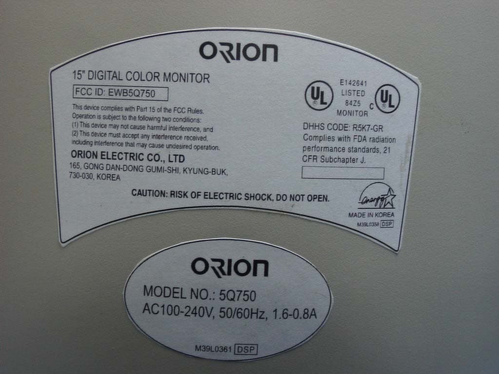
EWB5Q750
May 28, 200315" CRT Monitor
Equipment Class
JBP - Part 15 Class B Computing Device Peripheral
EWBLA530SH
Apr 13, 200315" LCD Monitor
Equipment Class
JBP - Part 15 Class B Computing Device Peripheral
EWBF9S956
Jan 22, 200319" Color Monitor
Equipment Class
JBP - Part 15 Class B Computing Device Peripheral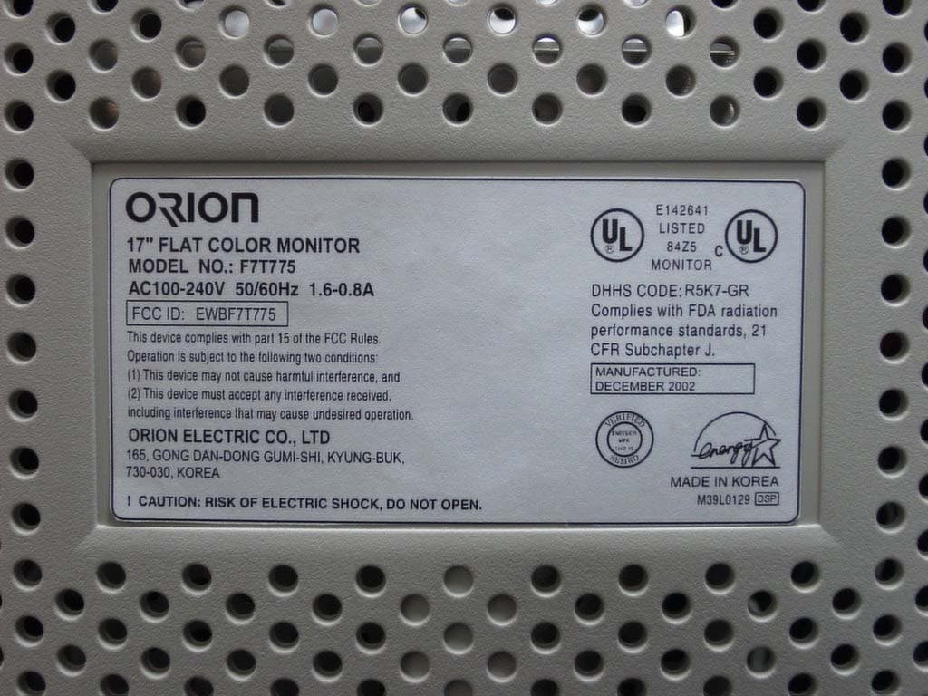
EWBF7T775
Jan 19, 2003Color Monitor
Equipment Class
JBP - Part 15 Class B Computing Device Peripheral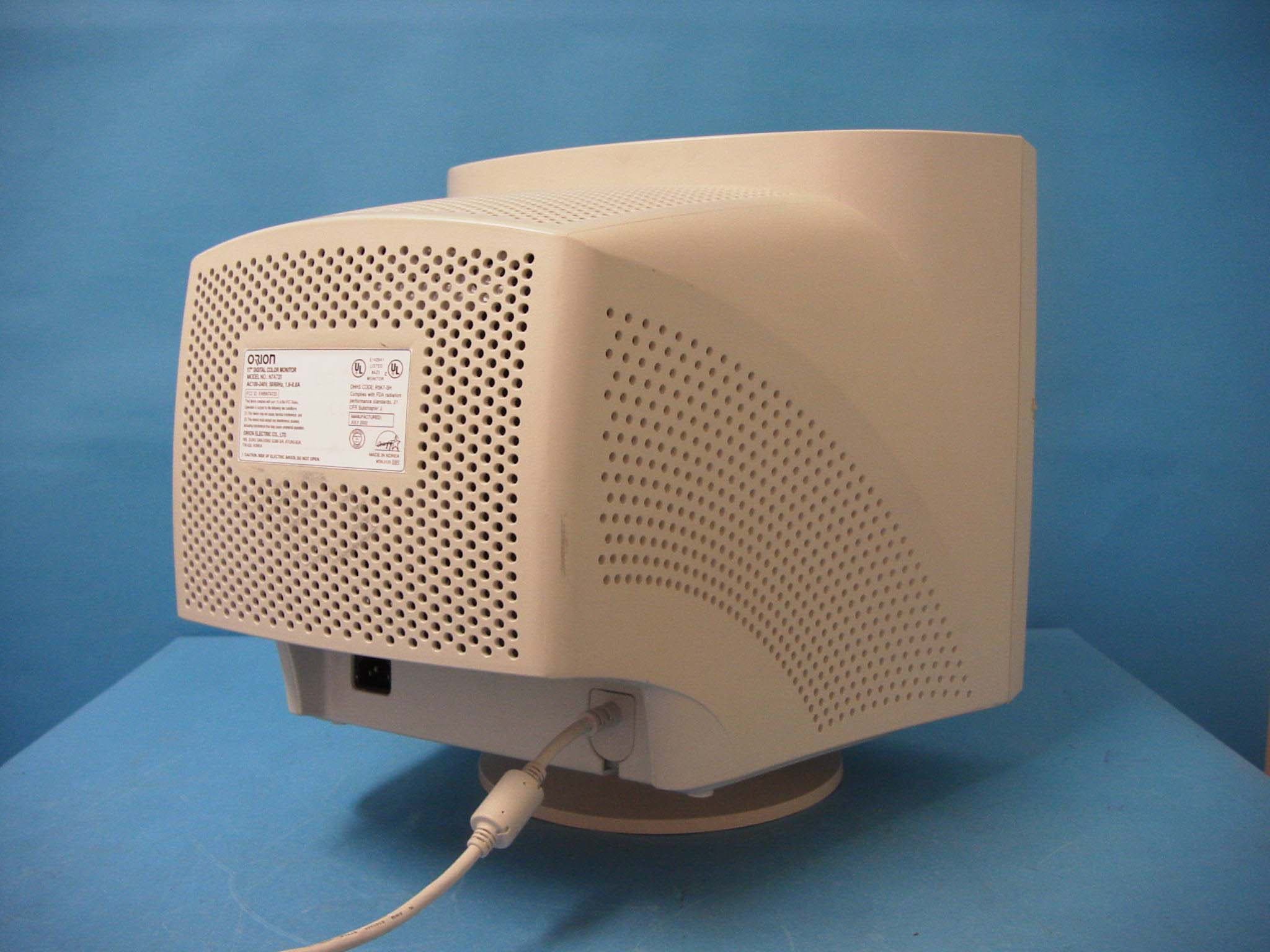
EWBN7A720
Sep 11, 2002Color Monitor
Equipment Class
JBP - Part 15 Class B Computing Device Peripheral