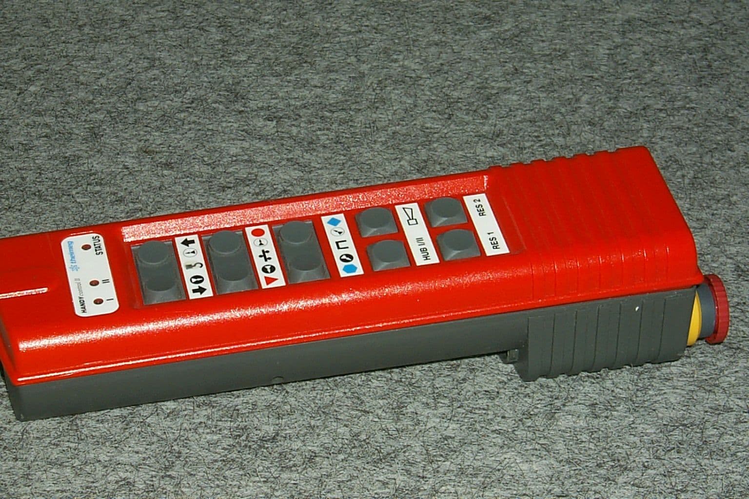
Click to zoom
Application Details
- Equipment Class
- DSR - Part 15 Remote Control/Security Device Transceiver
- Date of Grant
- Mar 21, 2000
- Application Purpose
- Original Equipment
- Date of Application
- Jan 17, 2000
- Frequency Range
- 412.00000000 - 466.00000000
- Country
- United States
Documents & Files
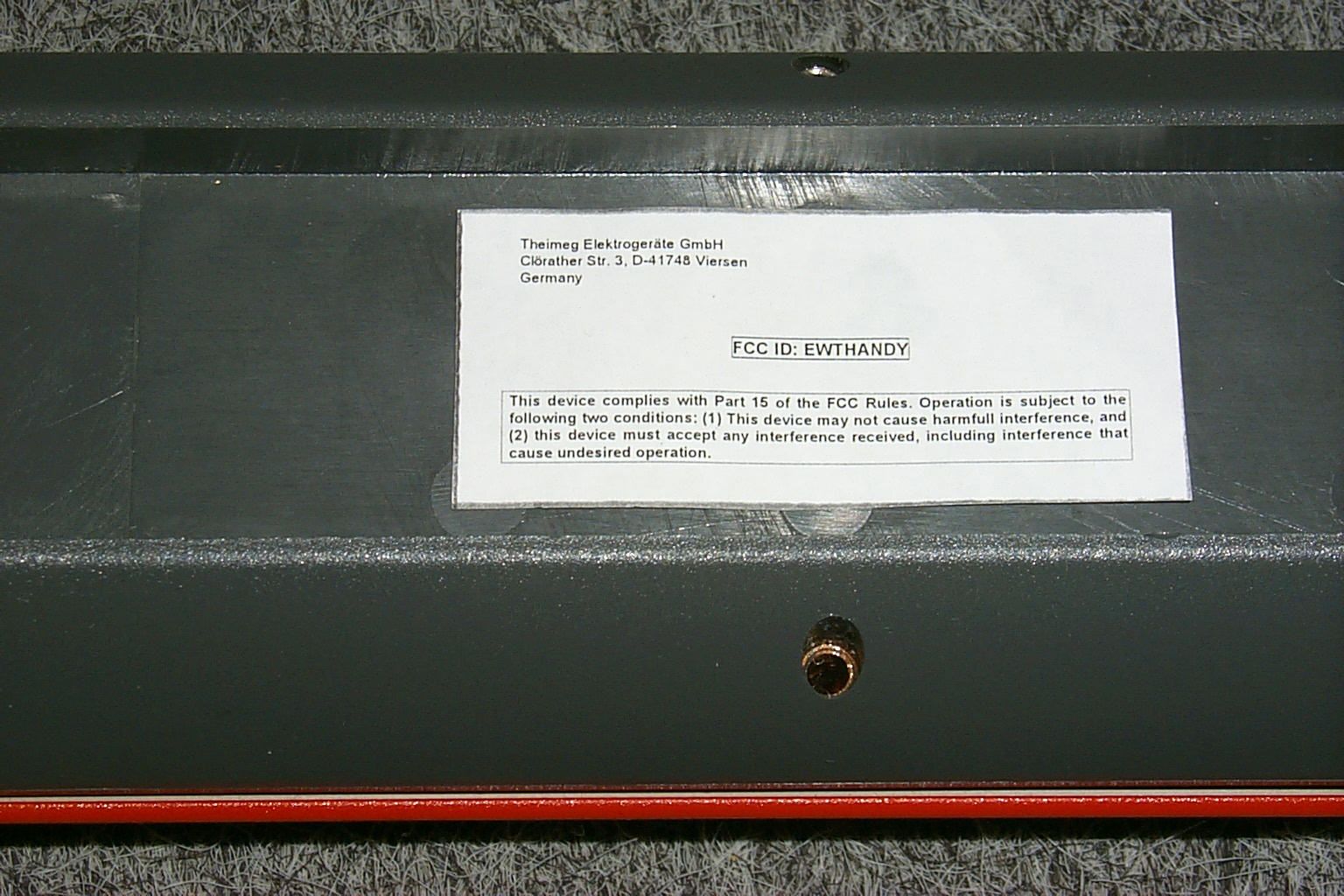
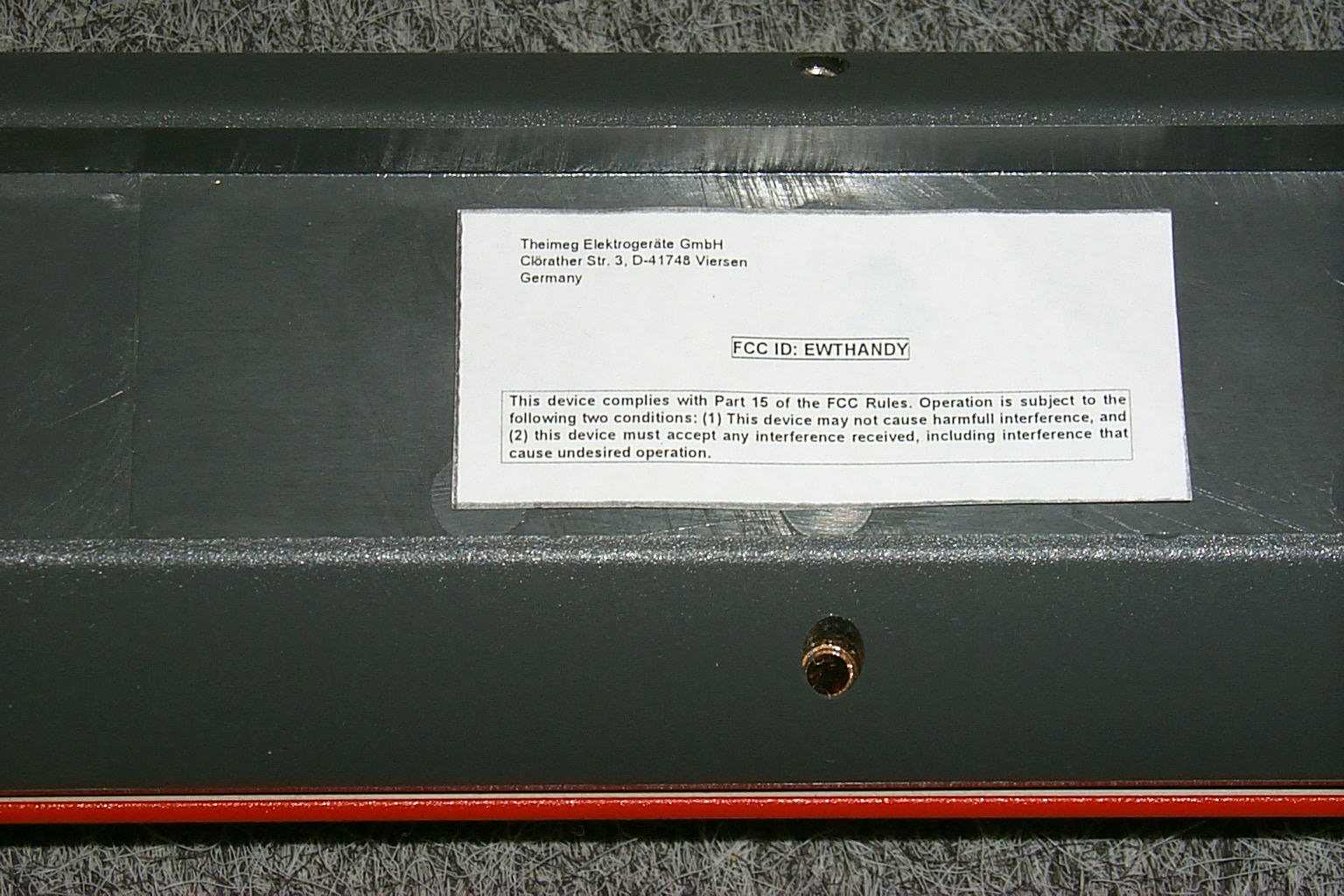
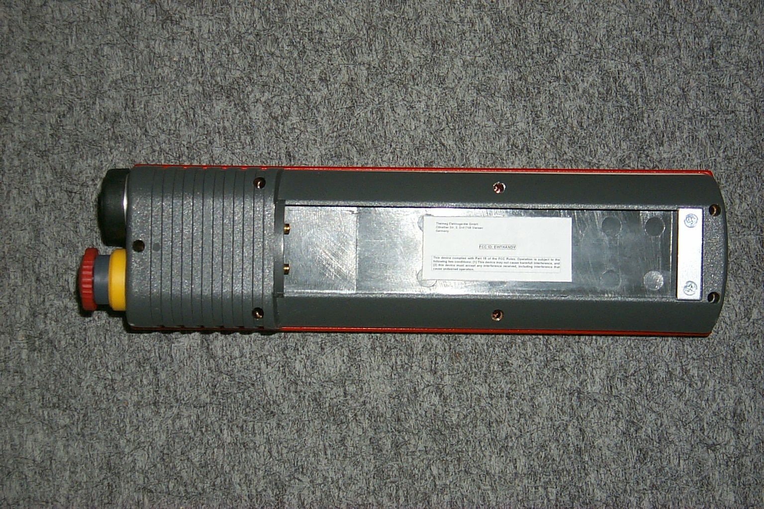
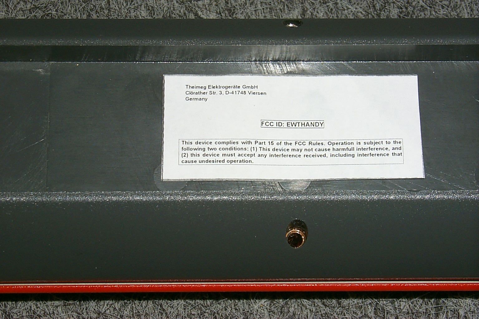
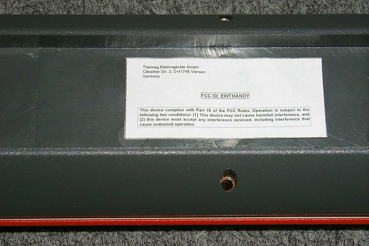
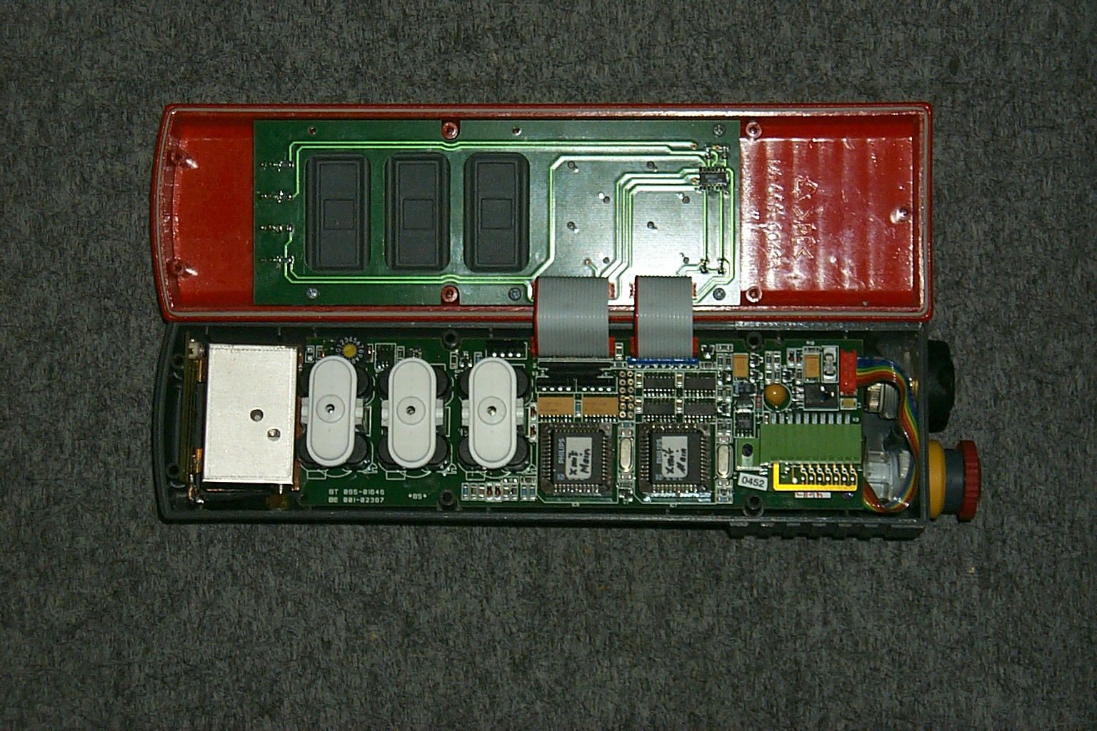
Document Text
Text extracted from the exhibit documents filed with the FCC. Open a document above to read the original.
Users Manual
Printed matter: Drawing no.: Author: Version: BED KF/17-HS (3/98 GB) 90.007-434-01 Siemes October 1998 MANUAL Radio remote control HANDYcontrol II General Installation Operation Fault in the system Maintenance HANDYcontrol II IIISTATUS theimegHANDYcontroll II HUB I/II RES 1RES 2 1.1Safety instructions 1.2Principle behind transmission of commands 2.1Components of the system 2.1.1Installation of the system 2.1.2.Installation dimensions receiver 3.1Control panel of the transmitter 3.1.1Switching on the transmitter 3.1.2Switching off the transmitter 3.1.3Passive shutdown of the transmitter 3.1.4Protection against inadvertent operation 3.2Test overview and test protocol 3.3.1Daily technical safety checks 3.3.1.1 Check manual/radio switchover (if applicable) 4Fault in the system 4.1Display and diagnosis in the transmitter 5Structure of the system 5.1Structure of the transmitter 5.2Transmitter controls 5.3Structure of the battery 1.3Addressing / coding 1.4Frequency coordination 2.2Connection plan for the receiver 2.3Interface specification 2.4Channel and Frequency setting 3.3.1.2 Check the drives and their zero position for interlocking 3.3.1.3 Check the active emergency-stop system 3.3.1.4 Check the passive emergency-stop system 3.4Maintenance 3.4.1Maintenance of the transmitter 3.4.2Maintenance of the receiver 3.5Proposed shutdown procedure in emergency situations 4.2Display and diagnosis in the receiver 5.4Structure of the receiver 5.5Ordering spare parts 5.6Technical data Annex Chapter 1-1-27 Page 1-1 Overall system Theimeg Elektronikgeräte GmbH & Co. D-41748 Viersen, Clörather Str. 3 Tel. (02162) 372-0, Telefax (02162) 30724 GENERALPage 1-1 to 1-4 INSTALLATION Page 2-1 to 2-18 Fault in the systemPage 4-1 to 4-4 Spare parts and technical data Page 5-1 to 5-9 OperationPage 3-1 to 3-11 GENERAL 1.1Safety instructions It is essential to observe the statutory regulations and guidelines applicable for the particular use of the system. In particular, it is essential to observe the following regulations and guidelines. Accident prevention regulations VBG9Cranes VBG9aLoad-carrying equipment used as hoists VBG8Winches, hoists and drawgear VBG12aIndustrial trucks VBG14Car lifts VBG40Diggers, loaders, planers, scrapers and special civil engineering machines Guidelines and safety regulations ZH 1/547Guidelines for radio remote control systems for cranes Guidelines for radio remote control systems for rope winches for Land- und Forstwirtschaft Bundesverband der landwirtschaftlichen Berufsgenos- senschaften e.V. . SEB660035Materials handling technology cranes with wireless control, basic principles and technical safety requirements SEB660040Direction of travel marking on crane systems DIN VDE regulations DIN VDE 0100 Regulations for installing heavy-duty power instal- lations with nominal voltages up to 1000V. DIN VDE 0160 Equipping heavy-duty power installations with electronic equipment. If they are linked to the construction or operation of the overall system, they must also be taken into account. Comments: Before the radio remote control system is used in practical applications, all operators must be in- structed in handling the equipment, and must fa- miliarise themselves with the system of remote control for the machine and the crane. Particular care must be observed with the control system during the familiarisation phase. It is essential to ensure that only one control unit can be used for controlling the system at any one time. When using the remote control system, it is es- sential to choose a safe place to stand and ensu- re that the entire working area can be viewed. If the radio remote control system is used for cra- nes and hoists, it is essential to ensure that the load remains in a stable position during travel and that an adequate safety distance is observed. Technical safety checks and maintenance of the remote control system must be performed and acknowledged as detailed in chapters 3.3.1 to 3.4. Chapter 1-1-27 Page 1-2 Overall system Theimeg Elektronikgeräte GmbH & Co. D-41748 Viersen, Clörather Str. 3 Tel. (02162) 372-0, Telefax (02162) 30724 Warranty and liability: All warranty and liability is excluded if the system or parts of the system are not installed correctly or damaged, or in the event of inexpert intervention in the system. This is also applicable if the prescribed checks and maintenance work are not performed by ap- propriately qualified and instructed personnel. Explanation of text markings ATTENTION! This is used if failure to follow operating instructi- ons, work instructions, prescribed procedures, etc. precisely or at all may result in damage to the equipment. WARNING! This is used if failure to follow operating instructi- ons, work instructions or prescribed procedures, etc. precisely or at all can lead to injury or fatal ac- cidents. NOTE: This is used to draw attention to ways of making work easier. Any changes or modifications not expressly ap- proved by the party responsible for compliance could void the user`s authority to operate the equipment. Page 1-3 Chapter 1-1-27 Overall system Theimeg Elektronikgeräte GmbH & Co. D-41748 Viersen, Clörather Str. 3 Tel. (02162) 372-0, Telefax (02162) 30724 1.2Principle behind trans- mission of commands In the transmitter, the control commands activated via the command generator are converted into se- rially coded pulse chains, so-called blocks of infor- mation. The signals generated in this way are broadcast via the transmitter antenna via a high- frequency carrier. The receiver evaluates the high-frequency carrier, filters the incoming serial information of the information blocks and recon- verts them into parallel commands. The com- mands are then sent to the downstream control system via output relays. DIP switches in the transmitter (for TH-KF/17-H) enable the radio remote control system to be con- figured in accordance with the precise require- ments. In receivers with a Harting connector, the potentials can be connecte…
Text truncated - open the document above for the full version.
Users Manual
Printed matter: Drawing no.: Author: Version: BED KF/17-HS (3/98 GB) 90.007-434-01 Siemes October 1998 MANUAL Radio remote control HANDYcontrol II General Installation Operation Fault in the system Maintenance HANDYcontrol II IIISTATUS theimegHANDYcontroll II HUB I/II RES 1RES 2 1.1Safety instructions 1.2Principle behind transmission of commands 2.1Components of the system 2.1.1Installation of the system 2.1.2.Installation dimensions receiver 3.1Control panel of the transmitter 3.1.1Switching on the transmitter 3.1.2Switching off the transmitter 3.1.3Passive shutdown of the transmitter 3.1.4Protection against inadvertent operation 3.2Test overview and test protocol 3.3.1Daily technical safety checks 3.3.1.1 Check manual/radio switchover (if applicable) 4Fault in the system 4.1Display and diagnosis in the transmitter 5Structure of the system 5.1Structure of the transmitter 5.2Transmitter controls 5.3Structure of the battery 1.3Addressing / coding 1.4Frequency coordination 2.2Connection plan for the receiver 2.3Interface specification 2.4Channel and Frequency setting 3.3.1.2 Check the drives and their zero position for interlocking 3.3.1.3 Check the active emergency-stop system 3.3.1.4 Check the passive emergency-stop system 3.4Maintenance 3.4.1Maintenance of the transmitter 3.4.2Maintenance of the receiver 3.5Proposed shutdown procedure in emergency situations 4.2Display and diagnosis in the receiver 5.4Structure of the receiver 5.5Ordering spare parts 5.6Technical data Annex Chapter 1-1-27 Page 1-1 Overall system Theimeg Elektronikgeräte GmbH & Co. D-41748 Viersen, Clörather Str. 3 Tel. (02162) 372-0, Telefax (02162) 30724 GENERALPage 1-1 to 1-4 INSTALLATION Page 2-1 to 2-18 Fault in the systemPage 4-1 to 4-4 Spare parts and technical data Page 5-1 to 5-9 OperationPage 3-1 to 3-11 GENERAL 1.1Safety instructions It is essential to observe the statutory regulations and guidelines applicable for the particular use of the system. In particular, it is essential to observe the following regulations and guidelines. Accident prevention regulations VBG9Cranes VBG9aLoad-carrying equipment used as hoists VBG8Winches, hoists and drawgear VBG12aIndustrial trucks VBG14Car lifts VBG40Diggers, loaders, planers, scrapers and special civil engineering machines Guidelines and safety regulations ZH 1/547Guidelines for radio remote control systems for cranes Guidelines for radio remote control systems for rope winches for Land- und Forstwirtschaft Bundesverband der landwirtschaftlichen Berufsgenos- senschaften e.V. . SEB660035Materials handling technology cranes with wireless control, basic principles and technical safety requirements SEB660040Direction of travel marking on crane systems DIN VDE regulations DIN VDE 0100 Regulations for installing heavy-duty power instal- lations with nominal voltages up to 1000V. DIN VDE 0160 Equipping heavy-duty power installations with electronic equipment. If they are linked to the construction or operation of the overall system, they must also be taken into account. Comments: Before the radio remote control system is used in practical applications, all operators must be in- structed in handling the equipment, and must fa- miliarise themselves with the system of remote control for the machine and the crane. Particular care must be observed with the control system during the familiarisation phase. It is essential to ensure that only one control unit can be used for controlling the system at any one time. When using the remote control system, it is es- sential to choose a safe place to stand and ensu- re that the entire working area can be viewed. If the radio remote control system is used for cra- nes and hoists, it is essential to ensure that the load remains in a stable position during travel and that an adequate safety distance is observed. Technical safety checks and maintenance of the remote control system must be performed and acknowledged as detailed in chapters 3.3.1 to 3.4. Chapter 1-1-27 Page 1-2 Overall system Theimeg Elektronikgeräte GmbH & Co. D-41748 Viersen, Clörather Str. 3 Tel. (02162) 372-0, Telefax (02162) 30724 Warranty and liability: All warranty and liability is excluded if the system or parts of the system are not installed correctly or damaged, or in the event of inexpert intervention in the system. This is also applicable if the prescribed checks and maintenance work are not performed by ap- propriately qualified and instructed personnel. Explanation of text markings ATTENTION! This is used if failure to follow operating instructi- ons, work instructions, prescribed procedures, etc. precisely or at all may result in damage to the equipment. WARNING! This is used if failure to follow operating instructi- ons, work instructions or prescribed procedures, etc. precisely or at all can lead to injury or fatal ac- cidents. NOTE: This is used to draw attention to ways of making work easier. Any changes or modifications not expressly ap- proved by the party responsible for compliance could void the user`s authority to operate the equipment. Page 1-3 Chapter 1-1-27 Overall system Theimeg Elektronikgeräte GmbH & Co. D-41748 Viersen, Clörather Str. 3 Tel. (02162) 372-0, Telefax (02162) 30724 1.2Principle behind trans- mission of commands In the transmitter, the control commands activated via the command generator are converted into se- rially coded pulse chains, so-called blocks of infor- mation. The signals generated in this way are broadcast via the transmitter antenna via a high- frequency carrier. The receiver evaluates the high-frequency carrier, filters the incoming serial information of the information blocks and recon- verts them into parallel commands. The com- mands are then sent to the downstream control system via output relays. DIP switches in the transmitter (for TH-KF/17-H) enable the radio remote control system to be con- figured in accordance with the precise require- ments. In receivers with a Harting connector, the potentials can be connecte…
Text truncated - open the document above for the full version.
Cover Letter(s)
Inglis Vollmacht.doc, KARTMANN, 18.09.98 CERTIFICATION OF AGENCY AGREEMENT I appoint Phillip Inglis to act as agent for our organization in the preparation of applications, including the signing there of, to make representations to the FEDERAL COMMUNICATIONS COMMISSION on our behalf and to receive and exchange data between the two parties: FEDERAL COMMUNICATIONS COMMISSION and CETECOM ICT SERVICES GMBH representing THEIMEG INC. It is further understood that this authorization covers only matters arising with the application of. THEIMEG INC. Dated this:December 1, 1999. Agency Agreement expiration date:June, 2000 By: Uwe Kartmann SignaturePrinted Title: Dipl.-Ing.Telephone: +49-681-8220 CETECOM ICT Services GmbH Untertuerkheimer Straße 6 - 10 D-66117 Saarbruecken Germany Telefon:+ 49 (0) 6 81 5 98 - 0 Telefax:+ 49 (0) 6 81 5 98 - 90 75 e-mail: e-mail: [email protected] Internet: http://www.cetecom.de Registered in Saarbruecken, Germany Reg.-No.: HRB Saarbruecken 11298 Chairman of the supervisory board: Ivo Rauh Managing Directors: Dr. Harald Ansorge Elisabeth Terodde
Cover Letter(s)
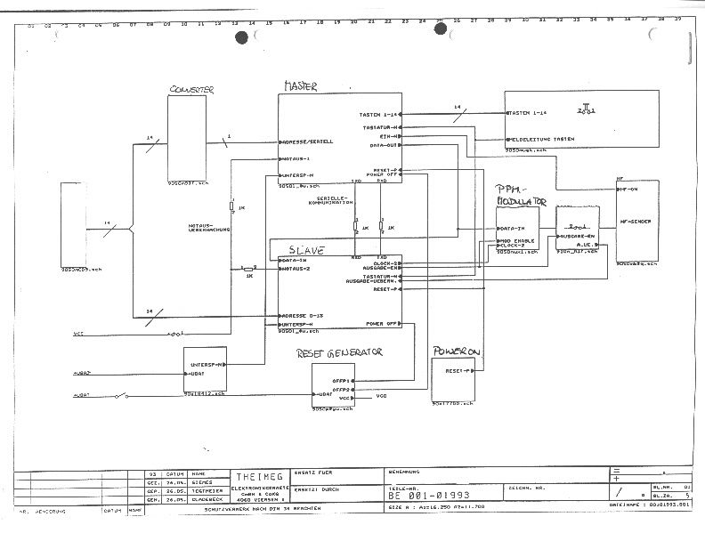
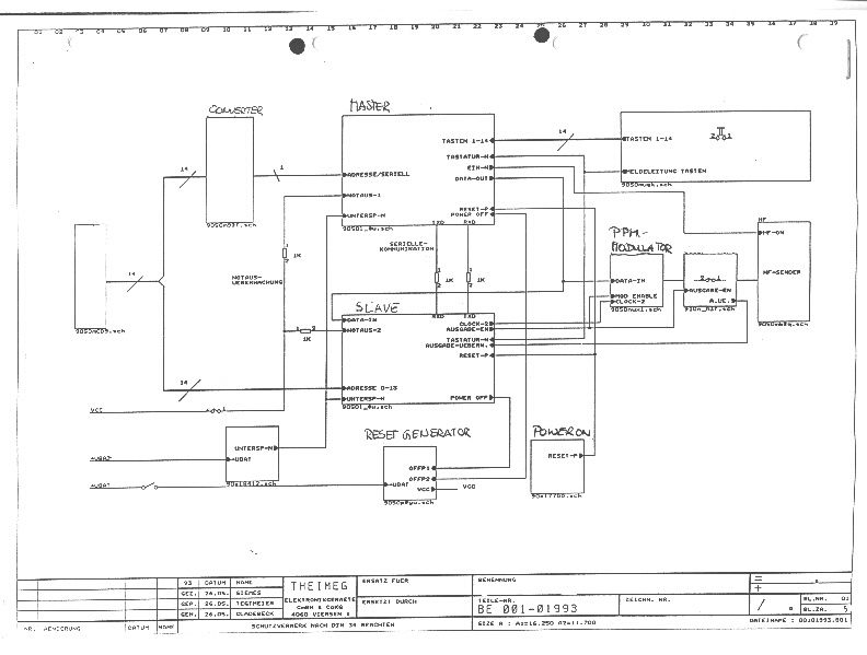
January 18, 2000 CONFIDENTIALITY REQUEST CONTAINED WITHIN Federal Communications Commission Authorization and Evaluation Division 7435 Oakland Mills Road Columbia, MD 21046 Re:Theimeg Inc., application for Remote Control Transmitter FCC ID: EWTHANDY Gentlemen: Theimeg Inc., PO Box 668, Stowe, VT 05672 herein submits an Application for Equipment Authorization to be followed by submission of a check for $XXXX.XX along with Form 159 for certification of a remote control device under FCC Rules Part 15 as required by the by the FCC Rules. Theimeg Inc., request, pursuant to 47CFR 0.459, post grant confidentiality for portions of the material contained in this application such that the identified material will be withheld from public inspection following the grant of this authorization. This material, as indicated by request for confidentiality of the items during the electronic submission process and further identified below, includes: 1.Circuit diagrams submitted as Equipment Authorization Electronic Filing attachment: "schematics" Exhibit #5 Specifically, this exhibit contains information relating to circuit function and complexity that could be of benefit to competitors. This material contains trade secrets and confidential information that Theimeg does not customarily release to the public and which is otherwise not generally available to the public. Please contact the undersigned by phone at 410-531-3439, by fax at 410-531-0807, by email at [email protected], or by correspondence at the address below if there are any further questions or additional information needed concerning this filing. Regards, (signed) Phillip Inglis 14085 Howard Rd. Dayton, MD. 21036
Cover Letter(s)
February 5, 2000 Federal Communications Commission Authorization and Evaluation Division 7435 Oakland Mills Road Columbia, MD 21046 Re:Theimeg Inc., application for Remote Control Transmitter FCC ID: EWTHANDY Gentlemen: Theimeg Inc., PO Box 668, Stowe, VT 05672 submitted an Application for Equipment Authorization for the referenced equipment on January 18, 2000. At that time the frequency range listed on the Form 731 was specified as 450 MHz. Theimeg wishes to modify the frequency range specified to permit operation between 412 MHz and 466 MHz. Accordingly, an additional test report has been submitted to cover the additional test requirements. Please contact the undersigned by phone at 410-531-3439, by fax at 410-531-0807, by email at [email protected], or by correspondence at the address below if there are any further questions or additional information needed concerning this filing. Regards, (signed) Phillip Inglis 14085 Howard Rd. Dayton, MD. 21036
Cover Letter(s)
Katie: Question regarding the statement in the test report that indicated that all measurements were made using a CISPR QP detector. I checked with Cetecom this morning regarding the statement. It was an error in formatting the test report. The error was contained in the original report and also in the second report for the additional frequencies at approximately 412 and 465 MHz. A letter was filed asking for the frequency range on the Form 731 to be changed to reflect the additional data. The measurements above 1 GHz were made on a spectrum analyzer in peak mode with a 1 MHz bandwidth. This error in the report format will be corrected in future submittals. To Cetecom’s knowledge there is no recognized standard specification for CISPR detection function and bandwidth for frequencies above 1 GHz. If you need further information, let me know. Regards, Phil
Cover Letter(s)
March 20, 2000 Phillip Inglis 14085 Howard Rd Dayton, MD 21036 Re: Theimeg equipment Dear Katie: Here is the response from the test firm, Cetecom, regarding your question about the AC power adapter. “We did not run line conducted data because the unit shown is for 220 volts. Theimeg is not providing a wall adapter recharger with the unit when the equipment is shipped to the United States. The importer will supply a commercially available 110 V AC wall adapter meeting any applicable FCC requirements.” “As shown in the photo, the 110 V AC wall adapter recharger plugs directly into a separate battery holder for charging purposes. There are no additional electronics in the battery holder. The 110 V AC charger does not plug into the transmitter as no provision has been made in the transmitter for this type of operation.” Regards, Phil
Operational Description
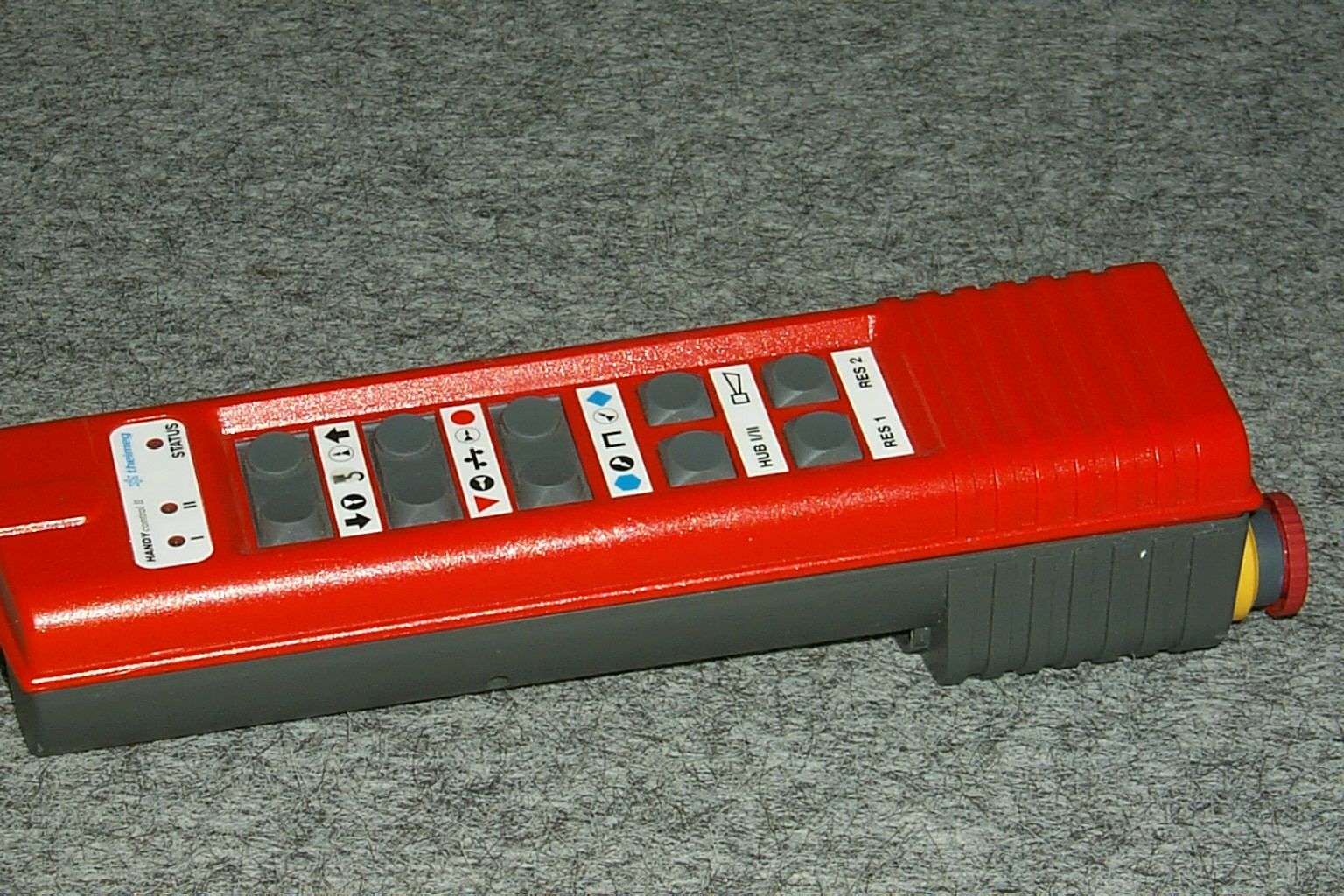
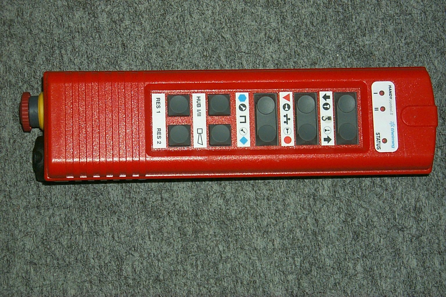
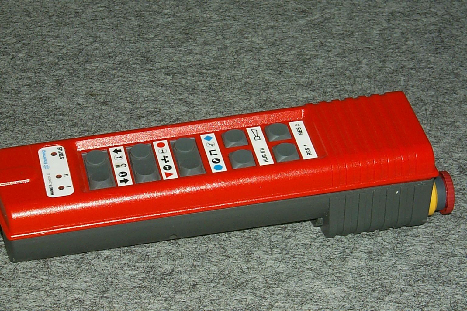
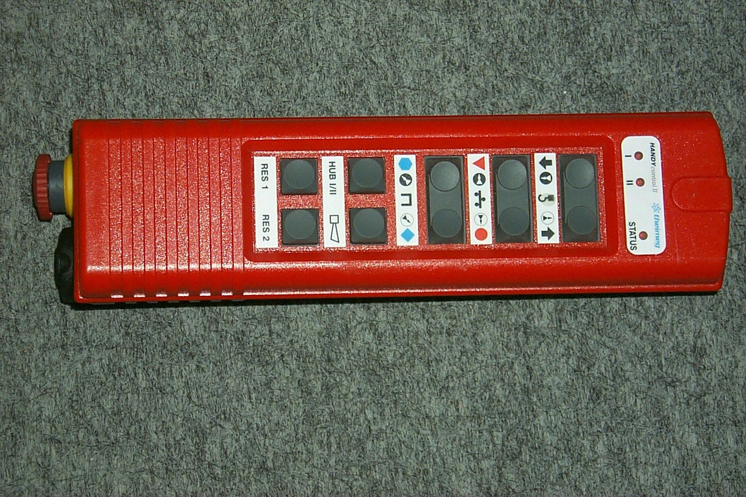
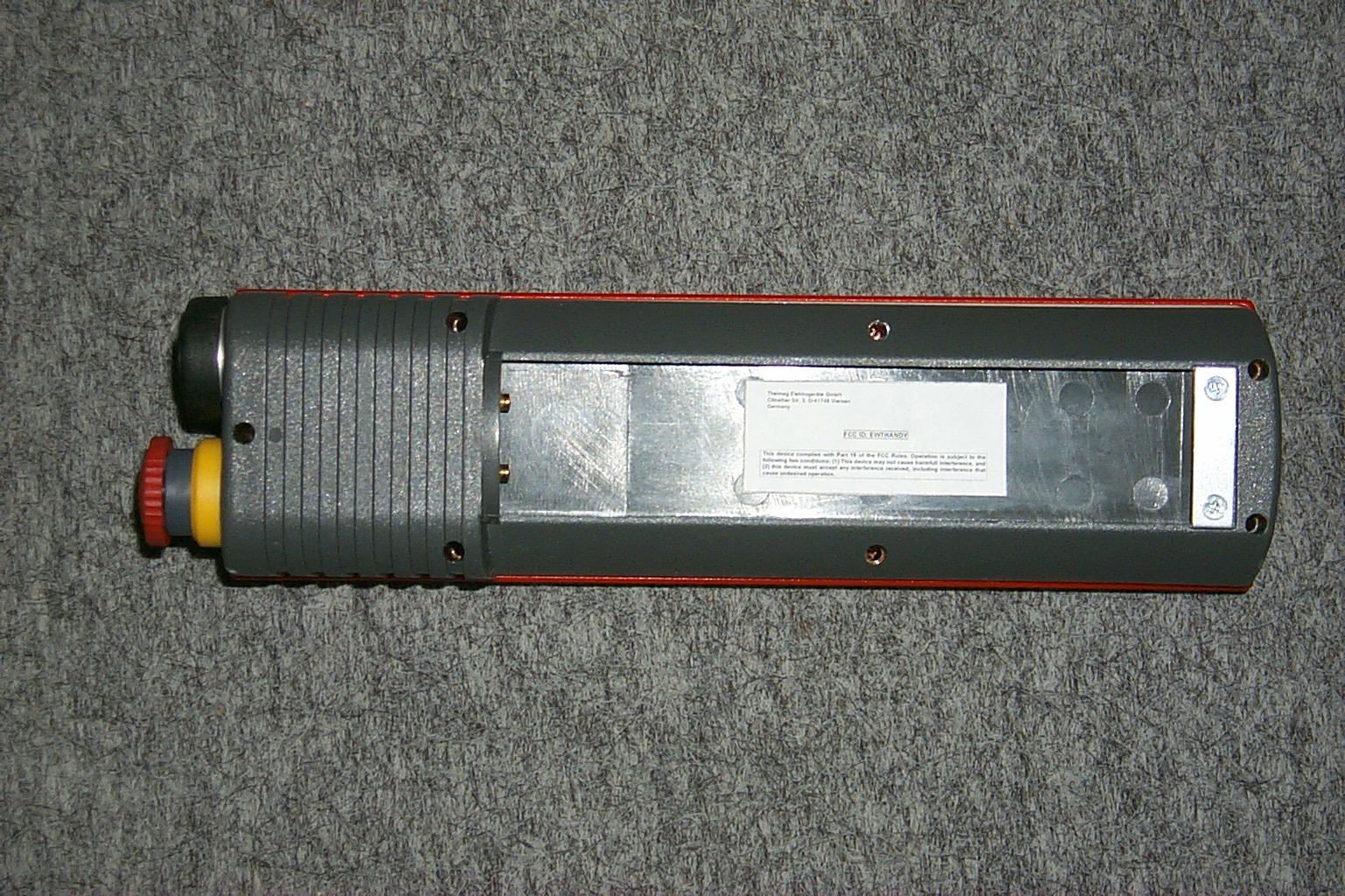
Expository statement: The HANDY transmitter is a hand held remote control transmitter used in conjunction with a separate receiver to control the movement of cranes. It is push-button activated and uses pulse position modulation for its control function. It is manually activated via the push-button and automatically cuts off when the button is released. Phillip Inglis
Test Report
CETECOM ICT Services GmbH Radio Satelite Communication Untertürkheimer Straße 6-10 . D-66117 SaarbrückenTelefon: +49 (0)681 598-9100Telefax: -9075 RSC14issue test report consist of18 PagesPage 1 (18) Test report no.: 2_1843-A/99 FCC Part 15.231 Theimeg HANDY Akkreditiertes Prüflaboratorium DAR-Registriernummer: TTI-P-G 166/98-00 vom 18.09.98 CETECOM ICT Services GmbH Test report no.: 2_1843-A/99Issue Date: 14.01.2000Page 2 (18) Table of Contents 1 General information 1.1 Notes 1.2 Testing laboratory 1.3 Details of applicant 1.4 Application details 1.5 Test item 1.6 Test standards 2 Technical test 2.1 Summary of test results 2.2 Test report 1 General information 1.1 Notes The test results of this test report relate exclusively to the item tested as specified in 1.5. The test report may only be reproduced or published in full. Reproduction or publication of extracts from the report requires the prior written approval of the CETECOM ICT Services GmbH. CETECOM ICT Services GmbH Test report no.: 2_1843-A/99Issue Date: 14.01.2000Page 3 (18) 1.2Testing laboratory CETECOM ICT Services GmbH 66117 Saarbrücken Untertürkheimer Straße 6 - 10 Deutschland Telefone: + 49 681 598 - 9000 Telefax : + 49 681 598 - 9075 E-mail: [email protected] Internet: www.cetecom.de Accredited testing laboratory DAR-registration number : TTI-P-G-166/98-00 vom 18.09.98 1.3Details of applicant Name :Theimeg Elektrogeräte GmbH Street :Clöratherstrasse 3 City :D-41748 Viersen Country :Germany Telephone:+49 2162 3720 Telefax :+49 2162 3724 Contact :Mr. Herrmann Telephone:+49 2161 3720 1.4Application details Date of receipt of application : 08.09.99 Date of receipt of test item : 08.09.99 Date of test: 08.09.99 1.5Test item Type of equipment :remote control transmitter Type designation:HANDY Manufacturer:applicant Street: City: Country: Additional informations:: Frequency:405 – 469 MHz during test 450.0 MHz Channel separation: opt. 25 kHz 12.5 kHZ Number of channels :max 64 Antenna:build –in Power supply:Tx: 7.2V DC NiCd -Accu Type of equipment :. - . Unmodulated carrier:not possible CETECOM ICT Services GmbH Test report no.: 2_1843-A/99Issue Date: 14.01.2000Page 5 (18) 2.2Testreport TEST REPORT FCC Part 15.231 FCC Part 15.209 Testreport no.: 2_1843-A/99 CETECOM ICT Services GmbH Test report no.: 2_1843-A/99Issue Date: 14.01.2000Page 6 (18) TEST REPORT REFERENCE LIST OF MEASUREMENTS The list of measured parameters called for in FCC Part 15.231 and FCC Part15.209 is given below. Paragraph PARAMETER TO BE MEASURED Page Transmitter parameters §15.231 (b) Maximum field strenght of emission7 §15.231 (a)Automatic deactivation8 §15.231 (c)Bandwidth of emission9 Test equipment listing10 Photographs of the equipment12 CETECOM ICT Services GmbH Test report no.: 2_1843-A/99Issue Date: 14.01.2000Page 7 (18) Equipment under test HANDY Ambient temperature: 20°°C Relative humidity : 48 % REFERENCE NUMBER(S) OF TEST EQUIPMENT USED (for reference numbers see test equipment listing) 17 - 24 EMISSION LIMITATIONS SUBCLAUSE § 15.231 (b) § 15.209 EMISSION LIMITATIONS all measurements are made up to the 10 th harmonic at 3m f (MHz) polari- zation amplitude of emission (μV/m) limit max. allowed emmision power (interpolation) actual attenuation below frequency of operation (dB)results 450.0vertical117411660 μV/m-Operating frequency 2250.0vertical2691166 μV/m 500μV/m (209) 13complies 2707.1vertical4731166 μV/m 500μV/m (209) 8complies >2707verticalno peak found1166 μV/m 500μV/m (209) complies Measurement uncertainty± 3dB LIMITSSUBCLAUSE § 15.231 (c) In any 100 kHz bandwidth outside the frequency band at least 20dB below the highest level of the permitted fundamental power. In addition, radiated emissions which fall in the restricted bands, as defined in §15.205(a), must also comply with the radiated emission limits specified in §15.209(a) (see §15.205(c)). All measurements are made with a CISPR quasi-peak equipment. CETECOM ICT Services GmbH Test report no.: 2_1843-A/99Issue Date: 14.01.2000Page 8 (18) Equipment under test HANDY Ambient temperature: 20°°C Relative humidity : 48 % REFERENCE NUMBER(S) OF TEST EQUIPMENT USED (for reference numbers see test equipment listing) 17 - 24 AUTOMATIC DEACTIVATION SUBCLAUSE § 15.231 (a) The transmitter is automatically deactivated within 5 seconds of being released. CETECOM ICT Services GmbH Test report no.: 2_1843-A/99Issue Date: 14.01.2000Page 9 (18) Equipment under test HANDY Ambient temperature: 20°°C Relative humidity : 48 % REFERENCE NUMBER(S) OF TEST EQUIPMENT USED (for reference numbers see test equipment listing) 17 - 24 Bandwidth of emissions SUBCLAUSE § 15.231 (c) TEST CONDITIONS FREQUENCY (MHz) at which –20 dBc occurs ±1.125 MHz at 450 MHz low high T nom ( 20 ) 0 CV nom ( 7.2 )V 449.989450.011 Measured frequencies (lowest and highest) f L = 449.989 MHz f H = 450.011MHz Measurement uncertainty ± 1 x 10 -5 LIMITS: §15.231 Under all test conditions no wider than 0.25% of the center frequency between 70 to 900 MHz, 0.5% above 900MHz. Bandwidth is determined at 20dB below modulated carrier. CETECOM ICT Services GmbH Test report no.: 2_1843-A/99Issue Date: 14.01.2000Page 10 (18) TEST EQUIPMENT AND ANCILLARIES USED FOR TESTS To simplify the identification on each page of the test equipment used, on each page of the test report, each item of test equipment and ancillaries such as cables are identified (numbered) by the Test Laboratory, below. NoInstrument/AncillaryTypeManufacturerSerial No. 01Spectrum Analyzer8566 AHewlett-Packard1925A00257 02Analyzer Display8566 AHewlett-Packard1925A00860 03Oscilloscope7633Tektronix230054 04Radio AnalyzerCMTA 54Rohde & Schwarz894 043/010 05System Power Supply6038 AHewlett-Packard2848A07027 06Signal Generator8111 AHewlett-Packard2215G00867 07Signal Generator8662 AHewlett-Packard2224A01012 08FunktionsgeneratorAFGURohde & Schwarz862 480/032 09RegeltrenntrafoMPLErfi91350 10NetznachbildungNNLA 8120Schwarzbeck8120331 11Relais-MatrixPSURohde & Schwarz893 285/020 12Power-Meter…
Text truncated - open the document above for the full version.
Test Report
CETECOM ICT Services GmbH Radio Satelite Communication Untertürkheimer Straße 6-10 . D-66117 SaarbrückenTelefon: +49 (0)681 598-9100Telefax: -9075 RSC14issue test report consist of18 PagesPage 1 (18) Test report no.: 2_1843-A/99 FCC Part 15.231 Theimeg HANDY Akkreditiertes Prüflaboratorium DAR-Registriernummer: TTI-P-G 166/98-00 vom 18.09.98 CETECOM ICT Services GmbH Test report no.: 2_1843-A/99Issue Date: 14.01.2000Page 2 (18) Table of Contents 1 General information 1.1 Notes 1.2 Testing laboratory 1.3 Details of applicant 1.4 Application details 1.5 Test item 1.6 Test standards 2 Technical test 2.1 Summary of test results 2.2 Test report 1 General information 1.1 Notes The test results of this test report relate exclusively to the item tested as specified in 1.5. The test report may only be reproduced or published in full. Reproduction or publication of extracts from the report requires the prior written approval of the CETECOM ICT Services GmbH. CETECOM ICT Services GmbH Test report no.: 2_1843-A/99Issue Date: 14.01.2000Page 3 (18) 1.2Testing laboratory CETECOM ICT Services GmbH 66117 Saarbrücken Untertürkheimer Straße 6 - 10 Deutschland Telefone: + 49 681 598 - 9000 Telefax : + 49 681 598 - 9075 E-mail: [email protected] Internet: www.cetecom.de Accredited testing laboratory DAR-registration number : TTI-P-G-166/98-00 vom 18.09.98 1.3Details of applicant Name :Theimeg Elektrogeräte GmbH Street :Clöratherstrasse 3 City :D-41748 Viersen Country :Germany Telephone:+49 2162 3720 Telefax :+49 2162 3724 Contact :Mr. Herrmann Telephone:+49 2161 3720 1.4Application details Date of receipt of application : 08.09.99 Date of receipt of test item : 08.09.99 Date of test: 08.09.99 1.5Test item Type of equipment :remote control transmitter Type designation:HANDY Manufacturer:applicant Street: City: Country: Additional informations:: Frequency:405 – 469 MHz during test 450.0 MHz Channel separation: opt. 25 kHz 12.5 kHZ Number of channels :max 64 Antenna:build –in Power supply:Tx: 7.2V DC NiCd -Accu Type of equipment :. - . Unmodulated carrier:not possible CETECOM ICT Services GmbH Test report no.: 2_1843-A/99Issue Date: 14.01.2000Page 5 (18) 2.2Testreport TEST REPORT FCC Part 15.231 FCC Part 15.209 Testreport no.: 2_1843-A/99 CETECOM ICT Services GmbH Test report no.: 2_1843-A/99Issue Date: 14.01.2000Page 6 (18) TEST REPORT REFERENCE LIST OF MEASUREMENTS The list of measured parameters called for in FCC Part 15.231 and FCC Part15.209 is given below. Paragraph PARAMETER TO BE MEASURED Page Transmitter parameters §15.231 (b) Maximum field strenght of emission7 §15.231 (a)Automatic deactivation8 §15.231 (c)Bandwidth of emission9 Test equipment listing10 Photographs of the equipment12 CETECOM ICT Services GmbH Test report no.: 2_1843-A/99Issue Date: 14.01.2000Page 7 (18) Equipment under test HANDY Ambient temperature: 20°°C Relative humidity : 48 % REFERENCE NUMBER(S) OF TEST EQUIPMENT USED (for reference numbers see test equipment listing) 17 - 24 EMISSION LIMITATIONS SUBCLAUSE § 15.231 (b) § 15.209 EMISSION LIMITATIONS all measurements are made up to the 10 th harmonic at 3m f (MHz) polari- zation amplitude of emission (μV/m) limit max. allowed emmision power (interpolation) actual attenuation below frequency of operation (dB)results 450.0vertical117411660 μV/m-Operating frequency 2250.0vertical2691166 μV/m 500μV/m (209) 13complies 2707.1vertical4731166 μV/m 500μV/m (209) 8complies >2707verticalno peak found1166 μV/m 500μV/m (209) complies Measurement uncertainty± 3dB LIMITSSUBCLAUSE § 15.231 (c) In any 100 kHz bandwidth outside the frequency band at least 20dB below the highest level of the permitted fundamental power. In addition, radiated emissions which fall in the restricted bands, as defined in §15.205(a), must also comply with the radiated emission limits specified in §15.209(a) (see §15.205(c)). All measurements are made with a CISPR quasi-peak equipment. CETECOM ICT Services GmbH Test report no.: 2_1843-A/99Issue Date: 14.01.2000Page 8 (18) Equipment under test HANDY Ambient temperature: 20°°C Relative humidity : 48 % REFERENCE NUMBER(S) OF TEST EQUIPMENT USED (for reference numbers see test equipment listing) 17 - 24 AUTOMATIC DEACTIVATION SUBCLAUSE § 15.231 (a) The transmitter is automatically deactivated within 5 seconds of being released. CETECOM ICT Services GmbH Test report no.: 2_1843-A/99Issue Date: 14.01.2000Page 9 (18) Equipment under test HANDY Ambient temperature: 20°°C Relative humidity : 48 % REFERENCE NUMBER(S) OF TEST EQUIPMENT USED (for reference numbers see test equipment listing) 17 - 24 Bandwidth of emissions SUBCLAUSE § 15.231 (c) TEST CONDITIONS FREQUENCY (MHz) at which –20 dBc occurs ±1.125 MHz at 450 MHz low high T nom ( 20 ) 0 CV nom ( 7.2 )V 449.989450.011 Measured frequencies (lowest and highest) f L = 449.989 MHz f H = 450.011MHz Measurement uncertainty ± 1 x 10 -5 LIMITS: §15.231 Under all test conditions no wider than 0.25% of the center frequency between 70 to 900 MHz, 0.5% above 900MHz. Bandwidth is determined at 20dB below modulated carrier. CETECOM ICT Services GmbH Test report no.: 2_1843-A/99Issue Date: 14.01.2000Page 10 (18) TEST EQUIPMENT AND ANCILLARIES USED FOR TESTS To simplify the identification on each page of the test equipment used, on each page of the test report, each item of test equipment and ancillaries such as cables are identified (numbered) by the Test Laboratory, below. NoInstrument/AncillaryTypeManufacturerSerial No. 01Spectrum Analyzer8566 AHewlett-Packard1925A00257 02Analyzer Display8566 AHewlett-Packard1925A00860 03Oscilloscope7633Tektronix230054 04Radio AnalyzerCMTA 54Rohde & Schwarz894 043/010 05System Power Supply6038 AHewlett-Packard2848A07027 06Signal Generator8111 AHewlett-Packard2215G00867 07Signal Generator8662 AHewlett-Packard2224A01012 08FunktionsgeneratorAFGURohde & Schwarz862 480/032 09RegeltrenntrafoMPLErfi91350 10NetznachbildungNNLA 8120Schwarzbeck8120331 11Relais-MatrixPSURohde & Schwarz893 285/020 12Power-Meter…
Text truncated - open the document above for the full version.
Test Report
CETECOM ICT Services GmbH Radio Satelite Communication Untertürkheimer Straße 6-10 . D-66117 SaarbrückenTelefon: +49 (0)681 598-9100Telefax: -9075 RSC14addendum to test report consist of15 P…
Text truncated - open the document above for the full version.
Contact Information
Applicant
David Stagg(Principal Systems Developer, Cattron Group)
Technical Contact
Non-Technical Contact
TRPPhillip Inglis
[email protected]410-531-3439
Technical Specifications
| # | Rule Parts | Frequency Range | Power Output |
|---|---|---|---|
| 1 | 15C | 412 MHz - 466 MHz | - |
Other Applications from Theimeg Elektronikgerdte GmbH & Co.

EWTTC100-200
Sep 06, 2000Remote Control Transmitter
Equipment Class
DSR - Part 15 Remote Control/Security Device TransceiverEWTTH-UHF-SKL-2
Dec 16, 1997TNB - Licensed Non-Broadcast Station Transmitter
Equipment Class
TNB - Licensed Non-Broadcast Station TransmitterEWTTH-UHF-TRX-SF
Dec 16, 1997TNB - Licensed Non-Broadcast Station Transmitter
Equipment Class
TNB - Licensed Non-Broadcast Station TransmitterEWT7YZTH-20DS-SMP
Apr 17, 1986TNB - Licensed Non-Broadcast Station Transmitter
Equipment Class
TNB - Licensed Non-Broadcast Station Transmitter