EZN5PRAWOS2000AWOS 2000
Val Avionics Limited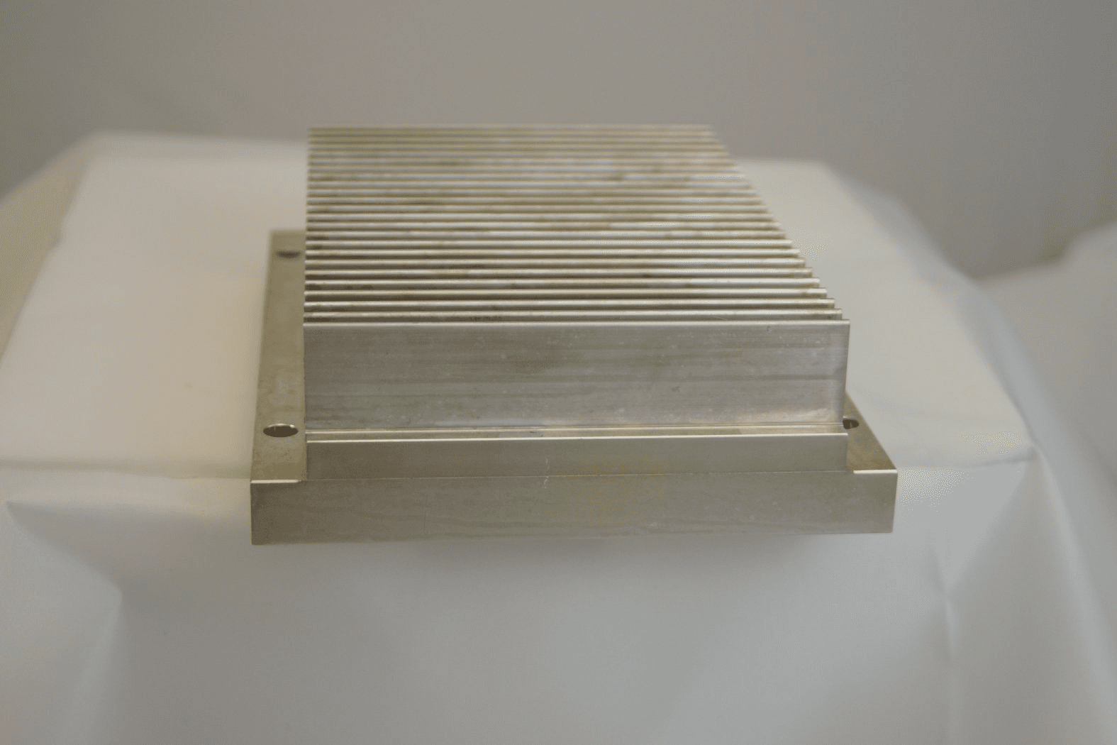
Click to zoom
Application Details
- Equipment Class
- TNB - Licensed Non-Broadcast Station Transmitter
- Date of Grant
- Jun 20, 2012
- Application Purpose
- Original Equipment
- Date of Application
- Jun 20, 2012
- Equipment Note
- AWOS 2000
- Frequency Range
- 118.00000000 - 136.97500000
- Company
- Val Avionics Limited
- Country
- United States
Documents & Files
Document Text
Text extracted from the exhibit documents filed with the FCC. Open a document above to read the original.
Users Manual
VAL AVIONICS LIMITED Communications Excellence AWOS 2000 INSTALLATION/OPERATION MANUAL Revision 1 VAL AVIONICS, LIMITED AWOS 2000 Val Avionics, Ltd. 3280 25 th Street SE P O Box 13025 Salem, Oregon 97309 Table of Contents GENERAL INFORMATION ....... 2 SPECIFICATIONS..................... 3 OPERATION ............................. 4 INSTALLATION......................... 5 A W O S 2 0 0 0 T R A N S M I T T E R INSTALLATION/OPERATION MANUAL REVISION 1 - JUNE 2010 PAGE 2 22 2 General Information The AWOS 2000 is a 760-channel communication transmitter and is designed to provide one way communication within the frequency range of 118.000 MHz to 136.975 MHz in 25 kHz increments. The AWOS 2000-communication transmitter was designed to conform to FAA Advisory Circular 150/5220-16B for use as a ground based VHF transmitter for Automated Weather Observing Systems (AWOS). The AWOS 2000 communication transmitter has Federal Communications Commission (FCC) type acceptance filed under FCC ID: EZN5PRAWOS2000 The AWOS 2000 consists of two major sections: Main Board and Transmitter Board. A W O S 2 0 0 0 T R A N S M I T T E R INSTALLATION/OPERATION MANUAL REVISION 1 - JUNE 2010 PAGE 3 33 3 Specifications Physical Dimensions: Width: 5.9 inches Height: 2.3 inches Length: 7.45 inches Weight 3.0 Lbs. Voltage: 13.75 ± 0.5 Vdc Current: Standby 250 mA; Transmit 2.0 A Frequency Range: 118.000 to 136.975 MHz Channel Spacing 25 kHz Frequency Stability: . 001% Spurious Emissions Greater Than 80 dB down from carrier Modulation Adjustable (50 to 90% Typical) Temperature Range -30 to +55 Degrees Celsius Transmit Power: 2.5 watts Emission 6K 00A3E Duty Cycle 100% Design All Solid State. Printed Circuit Board & Point to Point Wiring. Mounting Rigid Mounting, No Shock Mounting Required. FCC ID EZN5PRAWOS2000 Unit Part Number 0800202 A W O S 2 0 0 0 T R A N S M I T T E R INSTALLATION/OPERATION MANUAL REVISION 1 - JUNE 2010 PAGE 4 44 4 Operation CONTROLS: ON/OFF SWITCH turns on and off the main power to the unit. INDICATOR LIGHT Illuminates when the unit is powered up. DB-9 CONNECTOR connections for power, ground, mic audio, and transmit key are made at this connector. ANTENNA JACK connects to a broad band VHF 50 Ohm loaded antenna FREQUENCY CALIBRATION capacitor C427 can be adjusted to center the output frequency. MODULATION ADJUST potentiometer R423 can be adjusted to vary the modulation level. POWER ADJUST potentiometer R419 can be adjusted to vary the output power. DIPSWITHCES M0-M4 selects the whole MHz frequency (see table, page 8) DIPSWITCHES K2-K5 selects the tenth MHz frequency (see table, page 8) DIPSWITCHES K0-K1 selects the 25 kHz spacing (see table, page 8) A W O S 2 0 0 0 T R A N S M I T T E R INSTALLATION/OPERATION MANUAL REVISION 1 - JUNE 2010 PAGE 5 55 5 INSTALLATION This section contains suggestions and factors to consider before installing the AWOS 2000 transmitter. Close adherence to these suggestions will assure more satisfactory performance from the equipment. The AWOS 2000 installation will conform to standards designated by the customer, installing agency, and existing conditions as to the unit location and type of installation. The installing agency will supply and fabricate all external cables for interface to their system as appropriate. VAL Avionics, Ltd will supply the connectors required. Unpacking and Inspecting Unpack the equipment and inspect each item for evidence of damage incurred during shipment. If a damage claim must be filed, save the shipping container and all packing materials to substantiate your claim. The claim should be filed with the Transportation Company as soon as possible. The shipping container and packing material should be saved in any case in the event that storage or reshipment of the equipment is necessary. Installation Settings and Adjustments The AWOS unit should be allowed to operate in the transmit mode for a time period sufficient to allow the components and temperature to stabilize. Selecting Frequency. The desired frequency is selected by setting the eleven switches on DS401 and DS402 located on the bottom of the unit. The operating frequency is then selected by setting the switches in accordance with the Truth Table on page 8. Fine tuning the frequency is achieved by adjusting C427. (The AWOS 2000 is set at the factory at 118.9 MHz) Setting Power Level. Adjust R419 for the proper power setting. (2.5 watts). Setting Modulation. With a standard audio tone applied at the audio input adjust R423 to the desired modulation level. NOTE: FINAL MODULATION AND POWER LEVELS MUST BE SET WITH THE AWOS 2000 CONNECTED TO SITE ANTENNA. A W O S 2 0 0 0 T R A N S M I T T E R INSTALLATION/OPERATION MANUAL REVISION 1 - JUNE 2010 PAGE 6 66 6 Cooling Requirements The most important consideration to improved reliability of this equipment is to limit the maximum operating temperature. While modern designs consume less total energy, the heat dissipated per unit volume (Watts/cubic inch) remains much the same due to contemporary high density packaging techniques. While each individual unit may or may not require forced air cooling, the combined heat generated by several various units within a typical AWOS cabinet assembly can significantly degrade the reliability of the AWOS 2000 transmitter if provisions for adequate cooling are not incorporated in the particular installation. The AWOS 2000 transmitter is designed to operate within a temperature range of –30 to +55 degrees Celsius. The installing agency will be responsible for providing mounting and operating environments that do not exceed the operating temperature range specified. FAILURE TO PROVIDE THIS TYPE OF INSTALLATION ENVIRONMENT WILL VOID THE MANUFACTURERS WARRANTY! A W O S 2 0 0 0 T R A N S M I T T E R INSTALLATION/OPERATION MANUAL REVISION 1 - JUNE 2010 PAGE 7 77 7 PIN ASSIGNMENT The pin assignment and function for P401/J401 are as follows: PIN TERMINAL FUNCTION 1 GROUND (AUDIO RETURN) 2 POWER INPUT (+13.75 Vdc) 3 POWER INP…
Text truncated - open the document above for the full version.
Cover Letter(s)
6/7/2012 FCC Authorization and Evaluation Division 7435 Oakland Mills Road Columbia, MD 21046 Subject: AWOS 2000 The AWOS 2000 is a VHF transmitter designed for ground-based, single-station installation. We are seeking original certification approval for this new product under rule part 87. The majority of the testing was conducted at Val Avionics, Ltd. Headquarters, excluding Part 2.1053 Radiated Spurious Emissions, which was conducted at Northwest EMC, Inc. The unit tested is the same unit, serial number (Unit 1), and has not been modified or changed in any of these tests. FCC ID: EZN5PRAWOS2000 Thank you, James L. Harr, President Val Avionics, Ltd. (503) 370-9429 PO Box 13025 Salem, OR 97309
Cover Letter(s)
Equipment Applicant: Val Avionics LTD PO Box 13025 3280 25 th ST SE Salem, Oregon 97309 Exhibit 13 – Request for Confidentiality Val Avionics Flight Systems VHF COM-2000 Transceiver FCC ID: EZN5PRCOM2000 Model No. COM-2000 June 11, 2012 Federal Communications Commission Authorization and Evaluation Division 7435 Oakland Mills Road Columbia, Maryland 21046 To whom it may concern, We hereby respectfully request that under the provision of 47 CFR 0.459 and 0.457(d), the documents listed below and attached with this application for certification be provided with confidential status. • Schematics • Theory of Operation • Frequency Block Diagrams • Tune-up Procedure Any exhibit / information for which we have requested confidentiality, but which may not be accorded such treatment by the FCC, should be returned to us. The documents listed above contain trade secrets that are treated as confidential by us. Substantial competitive harm to us could result should they be made available to the public. Sincerely, James L. Harr President Val Avionics LTD June 11, 2012
External Photos
Equipment Applicant: Val Avionics LTD PO Box 13025 3280 25 th ST SE Salem, Oregon 97309 Exhibit 6 – External Photos Val Avionics Ground Systems VHF AWOS-2000 Transmitter FCC ID: EZN5PRAWOS2000 Model No. AWOS-2000 AWOS 2000 Bottom View AWOS 2000 Top View AWOS 2000 Controls and RF connector AWOS 2000 Rear View AWOS 2000 Left View AWOS 2000 Right View
ID Label/Location Info
AWOS 2000 Bottom – Including Label
Operational Description
Applications Single engine piston aircraft for applications of this antenna design. Consult your FBO or installation shop for best application information. Frequencies Covered 118-137 MHz CI 122 VHF Communication Designed specifically for mounting to the underside of an aircraft providing excellent radiation coverage for air-to-ground VHF communications. Bent configuration makes it ideally suited for helicopters and low wing aircraft. The CI 122 has been re-tested and upgraded to the new RTCA DO-160D environmental requirements and offers 118 to 137 MHz frequency associated with the DO-186A MOPS. Specifications For further information please contact: Cobham SATCOM Airborne Systems 577 Burning Tree Road Fullerton, California 92833 USA Tel: (01) 714-870-2420 Fax: (01) 714-870-5133 Email: [email protected] WARNING: Use factory supplied drawings and specifications for installation. Refer to FAA AC 43.13-2B for installation guidelines. www.cobham.com/comant Comant CI 122 VHF Communication 2008 Data Sheet The most important thing we build is trust Comant Industries, Inc. doing business as Cobham SATCOM Electrical Frequency 118-137 VSWR3.0:1 Maximum PolarizationVertical Radiation PatternOmnidirectional Impedance RF50 Ohms Power RF50 Watts Mechanical Weight0.75 lbs Max. Height18.50 inches Max. MaterialCast Housing / Stainless Steel FinishPolyurethane Enamel ConnectorBNC (female) Environmental Temperature-55 to +85 Celcius Altitude50,000 ft. Airspeed350 KTAS Federal Specifications FAA TSOC37d, C38d RTCA EnvironmentalDO-160D Gasket B12607-3Cork Neoprene
Parts List/Tune Up Info
VAL AVIONICS LTD AWOS 2000 VHF Transmitter Maintenance and Repair Manual Revision 1 April 2012 P/N 172211 VAL AVIONICS LTD VAL AVIONICS LTDVAL AVIONICS LTD VAL AVIONICS LTD AWOS 2000 AWOS 2000 AWOS 2000 AWOS 2000 – –– – VHF TRANSMITTER VHF TRANSMITTER VHF TRANSMITTER VHF TRANSMITTER MAINTENCE AND REPAIR MANUAL MAINTENCE AND REPAIR MANUALMAINTENCE AND REPAIR MANUAL MAINTENCE AND REPAIR MANUAL Revision 1 Page 2 of 13 April 2012 Table of Contents 1 Introduction.............................................................................................................................3 1.1 General Description .........................................................................................................3 1.2 Detailed Description.....................................................................................................3 1.2.1 Main Board Assembly ..............................................................................................4 1.2.1.1 Microcontroller........................................................................................................4 1.2.1.2 Power Supply Circuits ..............................................................................................5 1.2.1.3 Modulation Control..................................................................................................5 1.2.1.4 RF TX Generator.......................................................................................................6 1.2.2 Transmitter Board....................................................................................................7 2 Troubleshooting.......................................................................................................................8 2.1 Troubleshooting Equipment Required.............................................................................8 2.2 Initial Troubleshooting Operations..................................................................................8 2.3 Power Supply Check.........................................................................................................8 3 Disassembly Instructions .........................................................................................................9 3.1 Removal of the Covers.....................................................................................................9 3.2 Board and Module Disassembly ......................................................................................9 3.2.1 Main Board Removal........................................................................................................9 3.2.4 Transmitter Board Removal.............................................................................................9 3.3 Reassembling the Unit...................................................................................................10 4 Service and Testing................................................................................................................10 4.1 Initial Alignment / Return to Service..............................................................................10 4.1.1 Test Equipment Required ......................................................................................10 4.1.2 Setup ......................................................................................................................10 5 Appendix................................................................................................................................13 5.1 Table of Parts .................................................................................................................13 5.2 Specifications .................................................................................................................13 VAL AVIONICS LTD VAL AVIONICS LTDVAL AVIONICS LTD VAL AVIONICS LTD AWOS 2000 AWOS 2000 AWOS 2000 AWOS 2000 – –– – VHF TRANSMITTER VHF TRANSMITTER VHF TRANSMITTER VHF TRANSMITTER MAINTENCE AND REPAIR MANUAL MAINTENCE AND REPAIR MANUALMAINTENCE AND REPAIR MANUAL MAINTENCE AND REPAIR MANUAL Revision 1 Page 3 of 13 April 2012 1 Introduction This manual is intended to provide instructions and guidelines for the maintenance and repair of the VAL AWOS 2000. WARNING: This unit contains static sensitive devices. Service personnel must ensure that proper precautions are taken to prevent damage to this equipment from electrostatic discharge (ESD). Disassembly and repair should only be accomplished in an approved ESD workstation, and performed by properly trained and grounded personnel. 1.1 General Description The AWOS 2000 is a full-featured VHF transmitter designed for fixed remote installation. The AWOS 2000 uses a two-stage transmitter. The user interface consists of DIP-switches to control the active frequency and three adjustments for controlling power, modulation and frequency. The unit case is constructed from milled aluminum; the boards are constructed using high quality materials and use the latest techniques in manufacturing technology. In order to achieve the desired reliability, size, and power requirements, surface mounted components are used extensively. Specialized equipment and procedures are required to repair circuit boards having surface mounted components. Val Avionics LTD. does not authorize the repair of AWOS 2000 circuit boards. All circuit boards and assemblies from the AWOS 2000 can be economically replaced if necessary. The following modules and printed circuit board assemblies are available for replacement: Main Board: Printed circuit board, which contains the microcontroller, power supply circuitry, and audio components. Transmitter Board: Contains the two-stage transmitter. 1.2 Detailed Description Internally the AWOS 2000 is divided into two printed circuit boards: the main board and transmitter. The block diagram in Figure 1 below shows the relationships between the major circuits and modules within the AWOS 2000. VAL AVIONICS LTD VAL AVIONICS LT…
Text truncated - open the document above for the full version.
RF Exposure Info
Equipment Applicant: Val Avionics LTD PO Box 13025 3280 25 th ST SE Salem, Oregon 97309 RF Exposure Report Val Avionics Flight Systems VHF AWOS-2000 Transmitter FCC ID: EZN5PRAWOS2000 Model No. AWOS-2000 Overview: In accordance with the National Environmental Policy Act, this document has been created to justify and define the RF exposure environmental conditions of the AWOS 2000. Information: The AWOS 2000 is considered to be a fixed transmitter containing a 2.5- watt transmitter operating between 117.975 and 137.000 MHz. This device is designed to be permanently installed at a location and connected to an external antenna no less than 20 centimeters from any persons. The AWOS 2000 is certified under rule part 87, and is therefore categorically excluded from all environmental testing underneath 2.1091 or 2.1093. James L. Harr April 12, 2012
Test Report
Val Avionics Limited AWOS 2000 Report #: VALA0004 Report Prepared By Northwest EMC Inc. NORTHWEST EMC – (888) 364-2378 – www.nwemc.com California – Minnesota – Oregon – New York – Washington 22975 NW Evergreen Parkway Suite 400 Hillsboro, Oregon 97124 Certificate of Test Last Date of Test: February 14, 2012 Val Avionics Limited Model: AWOS 2000 Emissions Test Description Specification Test Method Pass/Fail Spurious Radiated Emissions FCC 87:2012 TIA/EIA-603-B:2002 Pass Deviations From Test Standards None Approved By: Tim O'Shea, Operations Manager NVLAP Lab Code: 200630-0 Test Facility The measurement facility used to collect the data is located at: Northwest EMC, Inc. 22975 NW Evergreen Parkway, Suite 400 Hillsboro, OR 97124 Phone: (503) 844-4066 Fax: 844-3826 This site has been fully described in a report filed with and accepted by the FCC (Federal Communications Commission) and Industry Canada (Site filing #2834D-1). This report must not be used to claim product certification, approval, or endorsement by NVLAP, NIST, or any agency of the federal government of the United States of America. Product compliance is the responsibility of the client, therefore the tests and equipment modes of operation represented in this report were agreed upon by the client, prior to testing. This Report may only be duplicated in its entirety. The results of this test pertain only to the sample(s) tested. The specific description is noted in each of the individual sections of the test report supporting this certificate of test. Revision History Revision 09/01/11 Revision Number Description Date Page Number 00 None Accreditations and Authorizations Revision 09/01/11 FCC Accredited by NVLAP for performance of FCC radio, digital, and ISM device testing. Our Open Area Test Sites, certification chambers, and conducted measurement facilities have been fully described in reports filed with the FCC and accepted by the FCC in letters maintained in our files. Northwest EMC has been accredited by ANSI to ISO / IEC Guide 65 as a product certifier. We have been designated by the FCC as a Telecommunications Certification Body (TCB). This allows Northwest EMC to certify transmitters to FCC specifications in accordance with 47 CFR 2.960 and 2.962. NVLAP Northwest EMC, Inc. is accredited under the National Voluntary Laboratory Accreditation Program (NVLAP) for satisfactory compliance with the requirements of ISO/IEC 17025 for Testing Laboratories. NVLAP is administered by the National Institute of Standards and Technology (NIST), an agency of the U.S. Commerce Department. The NVLAP accreditation encompasses Electromagnetic Compatibility Testing in accordance with the European Union EMC Directive 2004/108/EC, and ANSI C63.4. Additionally, Northwest EMC is accredited by NVLAP to perform radio testing in accordance with the European Union R&TTE Directive 1999/5/EEC, the requirements of FCC, and the RSS radio standards for Industry Canada. Industry Canada Accredited by NVLAP for performance of Industry Canada RSS and ICES testing. Our Open Area Test Sites and certification chambers comply with RSS-Gen, Issue 2 and have been filed with Industry Canada and accepted. Northwest EMC has been accredited by ANSI to ISO / IEC Guide 65 as a product certifier. We have been designated by NIST and recognized by Industry Canada as a Certification Body (CB) per the APEC Mutual Recognition Arrangement (MRA). This allows Northwest EMC to certify transmitters to Industry Canada technical requirements. (Site Filing Numbers - Hillsboro: 2834D-1, 2834D-2, Sultan: 2834C-1, Irvine: 2834B-1, 2834B-2, Brooklyn Park: 2834E-1) CAB Designated by NIST and validated by the European Commission as a Conformity Assessment Body (CAB) to conduct tests and approve products to the EMC directive and transmitters to the R&TTE directive, as described in the U.S. - EU Mutual Recognition Agreement. Australia/New Zealand The National Association of Testing Authorities (NATA), Australia has been appointed by the ACA as an accreditation body to accredit test laboratories and competent bodies for EMC standards. Accredited test reports or assessments by competent bodies must carry the NATA logo. Test reports made by an overseas laboratory that has been accredited for the relevant standards by an overseas accreditation body that has a Mutual Recognition Agreement (MRA) with NATA are also accepted as technical grounds for product conformity. The report should be endorsed with the respective logo of the accreditation body (NVLAP). Accreditations and Authorizations Revision 09/01/11 VCCI Accepted as an Associate Member to the VCCI, Acceptance No. 564. Conducted and radiated measurement facilities have been registered in accordance with Regulations for Voluntary Control Measures, Article 8. (Registration Numbers. - Hillsboro: C-1071, R- 1025, G-84, C-2687, T-1658, and R-2318, Irvine: R-1943, G-85, C-2766, and T-1659, Sultan: R-871, G-83, C-3265, and T-1511, Brooklyn Park: R-3125, G-86, G-141, C-3464, and T-1634). BSMI Northwest EMC has been designated by NIST and validated by C-Taipei (BSMI) as a CAB to conduct tests as described in the APEC Mutual Recognition Agreement (US0017). GOST Northwest EMC, Inc. has been assessed and accredited by the Russian Certification bodies Certinform VNIINMASH, CERTINFO, SAMTES, and Federal CHEC, to perform EMC and Hygienic testing for Information Technology Products. As a result of their laboratory assessment, they will accept test results from Northwest EMC, Inc. for product certification KCC Northwest EMC, Inc is a CAB designated by MRA partners and recognized by Korea. (Assigned Lab Numbers: Hillsboro: US0017, Irvine: US0158, Sultan: US0157, Brooklyn Park: US0175) VIETNAM Vietnam MIC has approved Northwest EMC as an accredited test lab. Per Decision No. 194/QD-QLCL (dated December 15, 2009), Northwest EMC test reports can be used for Vietnam approval submissions. SCOPE For details on the Scopes of our Accreditations, please visit: http://ww…
Text truncated - open the document above for the full version.
Test Report
Exhibit 6 Page 1 of 16 FCC ID: EZN5PRAWOS2000 4/17/2012 Equipment Applicant: Val Avionics LTD PO Box 13025 3280 25 th ST SE Salem, Oregon 97309 Exhibit 6 – Test Report Val Avionics Ground Systems VHF AWOS-2000 Transmitter FCC ID: EZN5PRAWOS2000 Model No. AWOS-2000 Exhibit 6 Page 2 of 16 FCC ID: EZN5PRAWOS2000 4/17/2012 6.0.3 Standard References 47 CFR 2 Code of Federal Regulations, Title 47, Part 2, “Frequency Allocations and Radio Treaty Matters; General Rules and Regulations” 47 CFR 87 Code of Federal Regulations, Title 47, Part 87, “Aviation Services” C63.4-2003 American National Standards Institute (ANSI), “Methods of Measurement of Radio- Noise Emissions from Low-Voltage Electrical and Electronic Equipment in the Range of 9 kHz to 40 GHz” 6.1 Test Requirements The AWOS 2000 transmitter is capable of operating in one frequency band consisting of the allocation across the 117.975 MHz to 137 MHz. Operation within this VHF band is subject to the regulations of multiple CFR parts including Parts 2 and 87 for FCC Certification for units deployable in the United States. Table 6.1-1 illustrates the test requirements list, as specified in FCC CFR Part 2. Table 6.1-1 FCC Certification Technical Requirement List 47 CFR Part 2 Requirements Requirement Description Compliance 2.1046 Power and Emissions Yes 2.1047 Modulation Characteristics Yes 2.1049 Occupied Bandwidth Yes 2.1051 Spurious Emissions Antenna Terminal; Spectrum Mask Yes 2.1053 Radiated Spurious Emissions Yes 2.1055 Carrier Frequency Stability; Temperature and Voltage Yes 6.1.1 Unit Description The AWOS 2000 transceiver is a Voice Modulated communications equipment utilizing Amplitude modulation, with a maximum power of 5W, operating in the 6K00A3E emission designator, with 25kHz channel spacing. 6.1.2 Test Results The test results presented in this report are for the certification testing performed on AWOS 2000, S/N UNIT 1. The majority of these tests were performed in partially shielded, low external RF, temperature and humidity controlled office, having the following ambient conditions: Temperature 23 C Humidity 33% Barometric Pressure: May 24 th – 101.41 kPa May 25 th – 101.10 kPa May 26 th – 101.15 kPa May 28 th – 102.27 kPa 6.2 Tests All tests excluding 6.2.4 Radiated Spurious Emissions were taken at: Val Avionics LTD 3280 25 th ST SE Salem, OR 97302 Exhibit 6 Page 3 of 16 FCC ID: EZN5PRAWOS2000 4/17/2012 All tests in this document were performed over a multiple day period, as noted in each section below. All tests listed below were performed by James Mac Innes, a Design and Systems Engineer for Val Avionics. 6.2.1 Power and Emissions With no modulation the unit power measurements were taken. The AWOS 2000 is designed to transmit 5Wrms maximum with 2.5Wrms nominal in the Aviation Communications Band of 117.975MHz to 137.000 MHz. As part of the installation documentation, the AWOS is to be installed as a single channel transmitter at a location. As part of the installation, the unit is to be set to 2.5W. Table 6.2.1-1 shows the power response over frequency range when following these instructions. Table 6.2.1-1: Frequency vs. Output Power This test was performed May 24 th , 2010 Test was performed by James A. Mac Innes James A. Mac Innes – Design Engineer Frequency Output Power 118 MHz 2.48 119 MHz 2.50 120 MHz 2.50 121 MHz 2.49 122 MHz 2.50 123 MHz 2.52 124 MHz 2.49 125 MHz 2.52 126 MHz 2.50 127 MHz 2.49 128 MHz 2.52 129 MHz 2.52 130 MHz 2.52 131 MHz 2.49 132 MHz 2.48 133 MHz 2.51 134 MHz 2.52 135 MHz 2.49 136 MHz 2.49 137 MHz 2.49 Exhibit 6 Page 4 of 16 FCC ID: EZN5PRAWOS2000 4/17/2012 6.2.2 Occupied Bandwidth The occupied bandwidth measurements for the AWOS-2000 are illustrated in Figures 6.2.2-1 through 6.2.2-3. These measurements were performed via antenna terminal conducted scans. These carrier measurements were taken with modulation of 2500 Hz tone at an input level 16dB greater than that necessary to produce 50 percent modulation as defined in 47 CFR 2.1049. The 99% occupied bandwidth measurement is an automated measurement performed by the Hewlett Packard 8595E spectrum analyzer. Figure 6.2.2-1 Occupied Bandwidth @ 118.9 MHz, AM Exhibit 6 Page 5 of 16 FCC ID: EZN5PRAWOS2000 4/17/2012 Figure 6.2.2-2 Occupied Bandwidth @ 127.9 MHz, AM Figure 6.2.2-3 Occupied Bandwidth @ 136.9 MHz, AM Exhibit 6 Page 6 of 16 FCC ID: EZN5PRAWOS2000 4/17/2012 6.2.2.1 Additional Notes regarding testing The HP 8595E has a variable attenuator internal to the unit. While the measurements show that there is an attenuator active, (in this case 10dB) the viewed signal measurements are calibrated to include this attenuation. The setup diagram is shown below in figure 6.2.2.1-1 Spectrum Analyzer HP 8595E AWOS 2000 RF out RF Attn -50dB Figure 6.2.2.1-1: Bandwidth conducted emissions setup This test was performed May 24 th , 2010 Test was performed by James A. Mac Innes James A. Mac Innes – Design Engineer 6.2.3 Spurious Emissions, Antenna Terminal Conducted spurious emissions at the antenna port were measured over the frequency range of 30 MHz to 2 GHz. The first set of test data provided in Section 6.2.3.1 is for the spectral mask within + 250% frequency offset of the carrier fundamental frequency. The second set of test data, Section 6.2.3.2, is for all conducted spurious emissions at >250% frequency offset from the carrier frequency. All measurements are taken on the HP 8595E using a 40 dB attenuator to prevent damage to the test device. Figure 6.2.3-1 shows the setup diagram. Spectrum Analyzer HP 8595E AWOS 2000 RF out RF Attn -40dB Figure 6.2.3-1: Spurious conducted emissions setup Exhibit 6 Page 7 of 16 FCC ID: EZN5PRAWOS2000 4/17/2012 6.2.3.1 Spectral Mask The spectral mask was measured at frequencies ± 250% of the allocated bandwidth centered at the mid-operating frequency of 127.5 MHz. The requirement limits are specified as -25 dBc @ 50-100% offset, -35 dBc @ 100-250% offset, and -53 dBc (43+10LogP) @ >250% offset. The same modulation schemes…
Text truncated - open the document above for the full version.
Test Setup Photos
AWOS 2000 prepared for temperature testing. AWOS 2000 – Close up Temperature testing Chamber Testing Equipment HP 8595E Spectrum Analyzer IFR 1200S – Acting as the tone generator and Freque ncy Counter Photo of complete Test Setup
Test Setup Photos
scan SRE 001.jpg SRE 002.jpg SPURIOUS RADIATED EMISSIONS PSA 2012.01.13 EMI 2008.1.9 scan SRE 003.jpg SRE 004.jpg SPURIOUS RADIATED EMISSIONS PSA 2012.01.13 EMI 2008.1.9 scan SRE 005.jpg SPURIOUS RADIATED EMISSIONS PSA 2012.01.13 EMI 2008.1.9
Contact Information
Applicant
James L. Harr(President)
Test Firm
Northwest EMC, Inc.Greg Kiemel
Technical Specifications
| # | Rule Parts | Frequency Range | Power Output | Emission | Tolerance |
|---|---|---|---|---|---|
| 1 | 87 | 118 MHz - 136.975 MHz | 2.52 W | 6K00A3E | 8.2600000000 ppm |
Other Applications from Val Avionics Limited
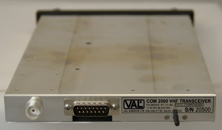
EZN5PRCOM2000
Jun 20, 2012COM 2000
Equipment Class
TNB - Licensed Non-Broadcast Station TransmitterEZNINS422
Jul 09, 1996CXX - Communications Rcvr for use w/ licensed Tx and CBs
Equipment Class
CXX - Communications Rcvr for use w/ licensed Tx and CBsEZNILS400
Nov 11, 1992CXX - Communications Rcvr for use w/ licensed Tx and CBs
Equipment Class
CXX - Communications Rcvr for use w/ licensed Tx and CBsEZN5PRCOM760
Apr 13, 1986Please submit the actual measurement data taken for modulation frequency response, Section 2.987(a), and frequency stability for variations in temperature tests.
Equipment Class
TNB - Licensed Non-Broadcast Station Transmitter