EZN5PRCOM2000COM 2000
Val Avionics Limited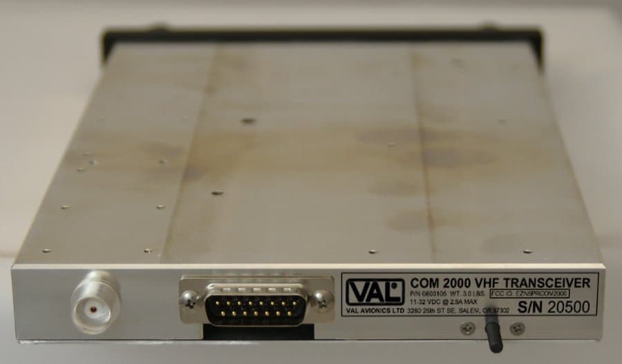
Click to zoom
Application Details
- Equipment Class
- TNB - Licensed Non-Broadcast Station Transmitter
- Date of Grant
- Jun 20, 2012
- Application Purpose
- Original Equipment
- Date of Application
- Jun 20, 2012
- Equipment Note
- COM 2000
- Frequency Range
- 118.00000000 - 136.97500000
- Company
- Val Avionics Limited
- Country
- United States
Documents & Files
Document Text
Text extracted from the exhibit documents filed with the FCC. Open a document above to read the original.
Users Manual
VAL AVIONICS LTD COM 2000 VHF Transceiver Installation and Operator’s Manual Revision 2 May 2012 P/N 172200 V A L A V I O N I C S L T D C O M 2 0 0 0 – V H F T R A N S C E I V E R I N S T A L L A T I O N A N D O P E R A T O R ’ S M A N U A L Revision 1 Page 2 of 20 May 2012 Revision History: October 2010 – Initial Printing May 2012 – Inserted section 1.4: FCC regarding FCC ID and emissions. V A L A V I O N I C S L T D C O M 2 0 0 0 – V H F T R A N S C E I V E R I N S T A L L A T I O N A N D O P E R A T O R ’ S M A N U A L Revision 1 Page 3 of 20 May 2012 Table of Contents 1 SECTION I - GENERAL INFORMATION 4 1.1 INTRODUCTION...........................................................................................................................................4 1.2 SCOPE ............................................................................................................................................................4 1.3 EQUIPMENT DESCRIPTION .......................................................................................................................4 1.4 FCC Emission Band ........................................................................................................................................5 1.5 SPECIFICATIONS .........................................................................................................................................6 1.6 EQUIPMENT SUPPLIED ..............................................................................................................................7 1.7 EQUIPMENT REQUIRED BUT NOT SUPPLIED .......................................................................................7 1.8 LICENSE REQUIREMENTS.........................................................................................................................7 2 SECTION II - INSTALLATION 8 2.1 GENERAL INFORMATION .........................................................................................................................8 2.1.1 Scope .....................................................................................................................................................8 2.2 UNPACKING AND INSPECTION................................................................................................................8 2.3 EQUIPMENT INSTALLATION PROCEDURES .........................................................................................8 2.3.1 Cooling Requirements ...........................................................................................................................8 2.3.2 Mounting Requirements ........................................................................................................................8 2.3.3 Wire Harness Fabrication ......................................................................................................................9 2.3.4 COM 2000 Installation ..........................................................................................................................9 2.4 POST INSTALLATION CHECK...................................................................................................................9 2.4.1 Operational Check ...............................................................................................................................10 2.4.2 Final Inspection ...................................................................................................................................10 2.5 LIMITATIONS .............................................................................................................................................10 3 SECTION III - OPERATION 11 3.1 GENERAL INFORMATION .......................................................................................................................11 3.1.1 Scope ...................................................................................................................................................11 3.1.2 Display Functions ................................................................................................................................11 3.1.3 User Controls .......................................................................................................................................11 3.2 System Configuration....................................................................................................................................13 3.2.1 Accessing Setup Functions ..................................................................................................................13 4 SECTION IV - WARRANTY AND SERVICE 14 4.1 LIMITED WARRANTY ..............................................................................................................................14 4.2 SERVICE ......................................................................................................................................................14 5 Appendix A – INSTALLATION DRAWINGS AND CONNECTOR LAYOUT 15 6 Appendix B – WIRING DIAGRAMS 18 7 Appendix C – Certifications 19 7.1 TSO Certification: .........................................................................................................................................19 8 Appendix D – INSTRUCTIONS FOR CONTINUED AIRWORTHINESS 20 8.1 MAINTENANCE INSTRUCTIONS ............................................................................................................20 Table 1: Specifications .................................................................................................................................. 6 Table 2: Equipment Supplied ........................................................................................................................ 7 Table 3: Equipment Not Supplied ................................................................................................................. 7 Table 4: Rear Connector Pin Functions .........................................…
Text truncated - open the document above for the full version.
Cover Letter(s)
9/1/2011 FCC Authorization and Evaluation Division 7435 Oakland Mills Road Columbia, MD 21046 Subject: COM 2000 The COM 2000 is a full-featured VHF transceiver designed for fixed panel installation. The COM 2000 uses a dual-heterodyne receiver and a three-stage transmitter. We are seeking original certification approval for this new product, the transmitter under rule part 87 and the receiver under rule part 18. The majority of the testing was conducted at Val Avionics, Ltd. Headquarters, excluding Part 2.1053 Radiated Spurious Emissions, which was conducted at Northwest EMC, Inc. The unit tested is the same unit, serial number 20500, and has not been modified or changed in any of these tests. FCC ID: EZN5PRCOM2000 Thank you, James L. Harr, President Val Avionics, Ltd. (503) 370-9429 PO Box 13025 Salem, OR 97309
Cover Letter(s)
Equipment Applicant: Val Avionics LTD PO Box 13025 3280 25 th ST SE Salem, Oregon 97309 Exhibit 13 – Request for Confidentiality Val Avionics Flight Systems VHF COM-2000 Transceiver FCC ID: EZN5PRCOM2000 Model No. COM-2000 May 8, 2012 Federal Communications Commission Authorization and Evaluation Division 7435 Oakland Mills Road Columbia, Maryland 21046 To whom it may concern, We hereby respectfully request that under the provision of 47 CFR 0.459 and 0.457(d), the documents listed below and attached with this application for certification be provided with confidential status. • Schematics • Theory of Operation • Frequency Block Diagrams • Tune-up Procedure Any exhibit / information for which we have requested confidentiality, but which may not be accorded such treatment by the FCC, should be returned to us. The documents listed above contain trade secrets that are treated as confidential by us. Substantial competitive harm to us could result should they be made available to the public. Sincerely, James L. Harr President Val Avionics LTD May 8, 2012
Cover Letter(s)
Northwest EMC TCB Compliance Opinion Rev. 7/1/10 VALA0005 Information about the Applicant Grantee (Company Name) VAL Avionics LTD FCC Contact Person James Leslie Harr Address 3280 25th St. SE City, State, Zip Salem, OR 97309 Job Number VALA0005 Model COM 2000 FCC ID EZN5PRCOM2000 Agent Approval Type Original Equipment Class GVH VHF Transmitter (GMDSS) Rule Part 87 Overview The CPM 2000 is a VHF transceiver installed in aircraft and used for communications. The device is certified under FCC rule part 87 Application did not request confidentiality. Recommendation All items have been resolved and completed to my satisfaction; therefore I recommend this application for approval. Signature Dave Tolman, TCB Committee 5/4/2012
External Photos
COM 2000 External Photographs: Front Top: Left: Right: Bottom: Rear:
ID Label/Location Info
Rear:
Internal Photos
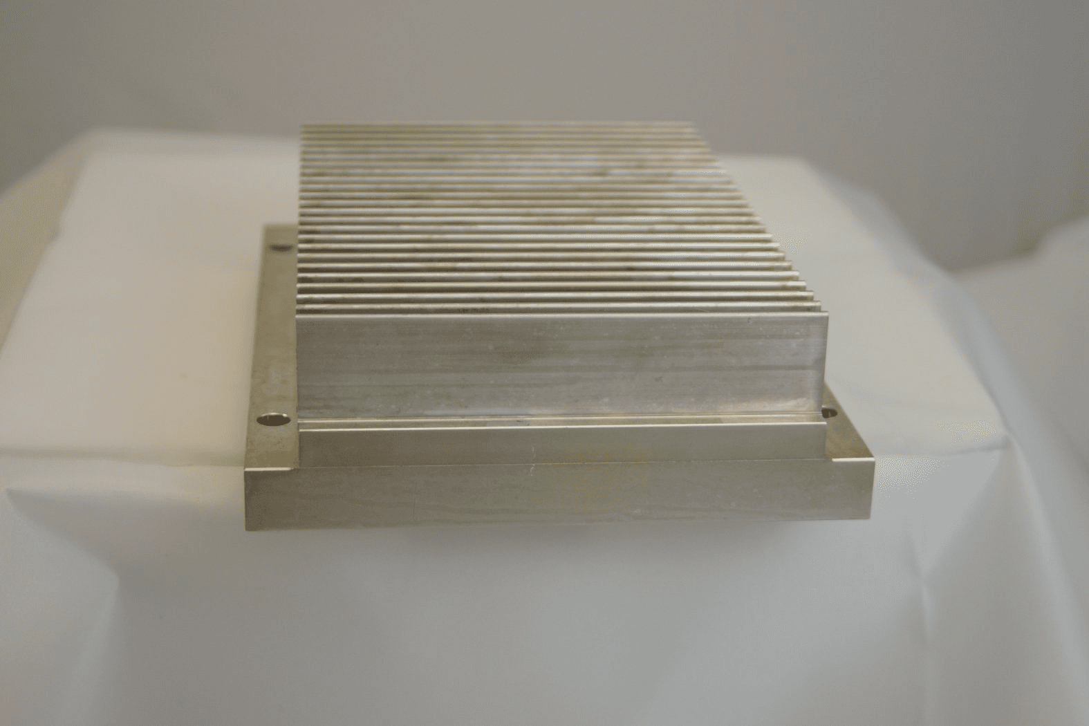
COM 2000 Internal Pictures: Assembled Interior: Mainboard Top: Mainboard Bottom: Transmitter Top: Transmitter Bottom: Receiver Top: Receiver Bottom:
RF Exposure Info
Equipment Applicant: Val Avionics LTD PO Box 13025 3280 25 th ST SE Salem, Oregon 97309 RF Exposure Report Val Avionics Flight Systems VHF COM-2000 Transceiver FCC ID: EZN5PRCOM2000 Model No. COM-2000 Overview: In accordance with the National Environmental Policy Act, this document has been created to justify and define the RF exposure environmental conditions of the COM 2000. Information: The COM 2000 is considered to be a fixed transmitter containing a less- than-10-watt transmitter operating between 117.975 and 137.000 MHz. This device is designed to be permanently installed in an aircraft and connected to an external antenna no less than 20 centimeters from the user or any passengers. The COM 2000 is certified under rule part 87, and is therefore categorically excluded from all environmental testing underneath 2.1091 or 2.1093. James L. Harr April 12, 2012
Test Report
Exhibit 6 Page 1 of 20 FCC ID: EZN5PRCOM2000 4/17/2012 Equipment Applicant: Val Avionics LTD PO Box 13025 3280 25 th ST SE Salem, Oregon 97309 Exhibit 6 – Test Report Val Avionics Flight Systems VHF COM-2000 Transceiver FCC ID: EZN5PRCOM2000 Model No. COM-2000 Exhibit 6 Page 2 of 20 FCC ID: EZN5PRCOM2000 4/17/2012 6.0.3 Standard References 47 CFR 2 Code of Federal Regulations, Title 47, Part 2, “Frequency Allocations and Radio Treaty Matters; General Rules and Regulations” 47 CFR 87 Code of Federal Regulations, Title 47, Part 87, “Aviation Services” C63.4-2003 American National Standards Institute (ANSI), “Methods of Measurement of Radio- Noise Emissions from Low-Voltage Electrical and Electronic Equipment in the Range of 9 kHz to 40 GHz” 6.1 Test Requirements The COM 2000 transceiver is capable of operating in one frequency band consisting of the allocation across the 117.975 MHz to 137 MHz. Operation within this VHF band is subject to the regulations of multiple CFR parts including Parts 2 and 87 for FCC Certification for units deployable in the United States. Table 6.1-1 illustrates the test requirements list, as specified in FCC CFR Part 2. Table 6.1-1 FCC Certification Technical Requirement List 47 CFR Part 2 Requirements Requirement Description Compliance 2.1046 Power and Emissions Yes 2.1047 Modulation Characteristics Yes 2.1049 Occupied Bandwidth Yes 2.1051 Spurious Emissions Antenna Terminal; Spectrum Mask Yes 2.1053 Radiated Spurious Emissions Yes 2.1055 Carrier Frequency Stability; Temperature and Voltage Yes 6.1.1 Unit Description The COM 2000 transceiver is a Voice Modulated communications equipment utilizing Amplitude modulation, with a maximum power of 10W, operating in the 6K00A3E emission designator, with a 25kHz channel spacing. 6.2 Test Results The test results presented in this report are for the certification testing performed on COM 2000, S/N 20500. The majority of these tests were performed in partially shielded, low external RF office, weather and dates are provided after each section. Exhibit 6 Page 3 of 20 FCC ID: EZN5PRCOM2000 4/17/2012 6.2.1 Power and Emissions With no modulation the unit power measurements were taken. The COM 2000 is designed to transmit 10Wrms maximum with 8Wrms nominal in the Aviation Communications Band of 117.975MHz to 137.000 MHz. Frequency Output Power 118 MHz 8.49 119 MHz 8.54 120 MHz 8.54 121 MHz 8.53 122 MHz 8.45 123 MHz 8.42 124 MHz 8.32 125 MHz 8.20 126 MHz 8.03 127 MHz 7.82 128 MHz 7.62 129 MHz 7.36 130 MHz 7.17 131 MHz 7.01 132 MHz 6.93 133 MHz 7.13 134 MHz 7.62 135 MHz 8.22 136 MHz 8.25 136.975 MHz 7.97 Table 6.2.1-1: Power Response 6.2.1.1 Testing Information Section 6.2.1 was performed on June 9, 2010 Internal temperature was 23 C Barometric Pressure was 101.08 kPa Humidity was 34% Test was performed by James A. Mac Innes James A. Mac Innes – Design Engineer Exhibit 6 Page 4 of 20 FCC ID: EZN5PRCOM2000 4/17/2012 6.2.2 Occupied Bandwidth The occupied bandwidth measurements for the COM-2000 are illustrated in Figures 6.2.2-1 through 6.2.2-3. These measurements were performed via antenna terminal conducted scans. These carrier measurements were taken with AM modulation of 2500 Hz tone at an input level 16dB greater than that necessary to produce 50 percent modulation as defined in 47 CFR 2.1049. The 99% occupied bandwidth measurement is an automated measurement performed by the Hewlett Packard 8595E spectrum analyzer. Figure 6.2.2-1 Occupied Bandwidth @ 118 MHz, AM Figure 6.2.2-2 Occupied Bandwidth @ 127 MHz, AM Exhibit 6 Page 5 of 20 FCC ID: EZN5PRCOM2000 4/17/2012 Figure 6.2.2-3 Occupied Bandwidth @ 136.975 MHz, AM 6.2.2.1 Additional Notes regarding test The HP 8595E has a variable attenuator internal to the unit. While the measurements show that there is an attenuator active, (in this case 20dB) the viewed signal measurements are calibrated to include this attenuation. The setup diagram is shown below in figure 6.2.2.1-1 Spectrum Analyzer HP 8595E COM 2000 RF out RF Attn -40dB Figure 6.2.2.1-1: Bandwidth conducted emissions setup Section 6.2.2 was performed on June 9, 2010 Internal temperature was 23 C Barometric Pressure was 101.08 kPa Humidity was 34% Test was performed by James A. Mac Innes James A. Mac Innes – Design Engineer Exhibit 6 Page 6 of 20 FCC ID: EZN5PRCOM2000 4/17/2012 6.2.3 Spurious Emissions, Antenna Terminal Conducted spurious emissions at the antenna port were measured over the frequency range of 30 MHz to 2 GHz. The first set of test data provided in Section 6.2.2.1 is for the spectral mask within + 250% frequency offset of the carrier fundamental frequency. The second set of test data, Section 6.2.2.2, is for all conducted spurious emissions at >250% frequency offset from the carrier frequency. All measurements are taken on the HP 8595E using a 50 dB attenuator to prevent damage to the test device. 6.2.3.1 Spectral Mask The spectral mask was measured at frequencies ± 250% of the allocated bandwidth centered at the mid-operating frequency of 127.9 MHz. The requirement limits are specified as -25 dBc @ 50-100% offset, -35 dBc @ 100-250% offset, and -53 dBc (43+10LogP) @ >250% offset. The same modulation schemes used for the Occupied Bandwidth were used for these measurements. Provided in this section are the unmodulated (CW) peak power levels measured at carrier frequency, which ranged from +38.6 dBm to +39.5 dBm for the nominal power output. Figure 6.2.3.1-1 Spectrum Mask @ 127.9 MHz, CW 6.2.3.2 Conducted Spurious Emissions This data illustrates the out-of-band conducted spurious emissions measured between 30 MHz and 2 GHz. The test requirement limit specified at >250% frequency offset from the carrier frequency is -53 dBc (43+10Log P) or, for 10 W maximum power output, approximately -13 dBm. Exhibit 6 Page 7 of 20 FCC ID: EZN5PRCOM2000 4/17/2012 Figure 6.2.3.2-1 Conducted spurious emissions, 127 MHz (30 MHz – 500 MHz) Figure 6.2.3.2-2 Conducted spurious emissions, 127 MHz (500 MHz – 1000 MHz) Exhibit 6 Pag…
Text truncated - open the document above for the full version.
Test Report
Val Avionics Ltd. COM 2000 Report #: VALA0005 Report Prepared By Northwest EMC Inc. NORTHWEST EMC – (888) 364-2378 – www.nwemc.com California – Minnesota – Oregon – New York – Washington 22975 NW Evergreen Parkway Suite 400 Hillsboro, Oregon 97124 Certificate of Test Last Date of Test: February 14, 2012 Val Avionics Ltd. Model: COM 2000 Emissions Test Description Specification Test Method Pass/Fail Spurious Radiated Emissions FCC 15.109:2012 Class B ANSI C63.4:2009 Pass Spurious Radiated Emissions FCC 87:2012 TIA/EIA-603-B:2002 Pass Deviations From Test Standards None Approved By: Don Facteau, IS Manager NVLAP Lab Code: 200630-0 Test Facility The measurement facility used to collect the data is located at: Northwest EMC, Inc. 22975 NW Evergreen Parkway, Suite 400 Hillsboro, OR 97124 Phone: (503) 844-4066 Fax: 844-3826 This site has been fully described in a report filed with and accepted by the FCC (Federal Communications Commission) and Industry Canada (Site filing #2834D-1). This report must not be used to claim product certification, approval, or endorsement by NVLAP, NIST, or any agency of the federal government of the United States of America. Product compliance is the responsibility of the client, therefore the tests and equipment modes of operation represented in this report were agreed upon by the client, prior to testing. This Report may only be duplicated in its entirety. The results of this test pertain only to the sample(s) tested. The specific description is noted in each of the individual sections of the test report supporting this certificate of test. Revision History Revision 09/01/11 Revision Number Description Date Page Number 00 None Accreditations and Authorizations Revision 02/21/2012 United States FCC - Designated by the FCC as a Telecommunications Certification Body (TCB). Certification chambers, Open Area Test Sites, and conducted measurement facilities are listed with the FCC. \ A2LA - Accredited by A2LA to ISO / IEC Guide 65 as a product certifier. This allows Northwest EMC to certify transmitters to FCC and IC specifications. NVLAP - Each laboratory is accredited by NVLAP to ISO 17025. The scope includes radio, ITE, and medical standards from around the world. See: http://www.nwemc.com/accreditations/ Canada IC - Recognized by Industry Canada as a Certification Body (CB). Certification chambers and Open Area Test Sites are filed with IC. European Union European Commission – Validated by the European Commission as a Conformity Assessment Body (CAB) under the EMC directive and as a Notified Body under the R&TTE Directive. Australia/New Zealand ACMA - Recognized by ACMA as a CAB for the acceptance of test data. Korea KCC / RRA - Recognized by KCC’s RRA as a CAB for the acceptance of test data. Japan VCCI - Associate Member of the VCCI. Conducted and radiated measurement facilities are registered. Taiwan BSMI – Recognized by BSMI as a CAB for the acceptance of test data. NCC - Recognized by NCC as a CAB for the acceptance of test data. Singapore IDA – Recognized by IDA as a CAB for the acceptance of test data. Hong Kong OFTA – Recognized by OFTA as a CAB for the acceptance of test data. Vietnam MIC – Recognized by MIC as a CAB for the acceptance of test data. Russia GOST – Accredited by Certinform VNIINMASH, CERTINFO, SAMTES, and Federal CHEC to perform EMC and Hygienic testing for Information Technology products to GOST standards. Locations Revision 2/23/12 Oregon Labs EV01-EV12 22975 NW Evergreen Pkwy, #400 Hillsboro, OR 97124 (503) 844-4066 California Labs OC01-OC13 41 Tesla Irvine, CA 92618 (949) 861-8918 New York Labs WA01-WA04 4939 Jordan Rd. Elbridge, NY 13060 (315) 685-0796 Minnesota Labs MN01-MN08 9349 W Broadway Ave. Brooklyn Park, MN 55445 (763) 425-2281 Washington Labs SU01-SU07 14128 339 th Ave. SE Sultan, WA 98294 (360) 793-8675 VCCI C-1071, R-1025, G-84, C-2687, T-1658, R-2318 R-1943, G-85, C-2766, T-1659, G-548 R-3125, G-86, G-141, C-3464, T-1634 R-871, G-83, C-3265, T-1511 Industry Canada 2834D-1, 2834D-2 2834B-1, 2834B-2, 2834B-3 2834E-1 2834C-1 Product Description Revision 09/01/11 Client and Equipment Under Test (EUT) Information Company Name: Val Avionics Ltd. Address: 3280 25th Street SE City, State, Zip: Salem, OR 97302 Test Requested By: Jim Harr Model: COM 2000 First Date of Test: February 14, 2012 Last Date of Test: February 14, 2012 Receipt Date of Samples: February 14, 2012 Equipment Design Stage: Production Equipment Condition: No Damage Information Provided by the Party Requesting the Test Functional Description of the EUT (Equipment Under Test): Aircraft Transceiver Testing Objective: These tests were selected to satisfy the EMC requirements requested by the client. Configurations Revision 09/01/11 Configuration 1 VALA0005 EUT Description Manufacturer Model/Part Number Serial Number Aircraft Transceiver Val Avionics Limited COM 2000 20500 Peripherals in test setup boundary Description Manufacturer Model/Part Number Serial Number DC Bench Supply MPJA 9950 PS 006708 Terminator Fairview Microwave ST6N-20 none Cables Cable Type Shield Length (m) Ferrite Connection 1 Connection 2 Speaker leads No 1.25m No Aircraft Transceiver Unterminated DC Power No 1.25m No Aircraft Transceiver Lab power Supply Microphone No 1.25m No Aircraft Transceiver Unterminated Headset No 1.25m No Aircraft Transceiver Unterminated PA = Cable is permanently attached to the device. Shielding and/or presence of ferrite may be unknown. Modifications Revision 09/01/11 Equipment Modifications Item Date Test Modification Note Disposition of EUT 1 2/14/2012 Transmitter Spurious Radiated Emissions Tested as delivered to Test Station. No EMI suppression devices were added or modified during this test. EUT remained at Northwest EMC following the test. 2 2/14/2012 Receiver Spurious Radiated Emissions Tested as delivered to Test Station. No EMI suppression devices were added or modified during this test. EUT remained at Northwest EMC following the test. description MODES OF OPE…
Text truncated - open the document above for the full version.
Test Setup Photos
scan Tx SRE 001.jpg Tx SRE 002.jpg RADIATED EMISSIONS PSA 2012.01.13 EMI 2008.1.9 scan Tx SRE 001.jpg Tx SRE 002.jpg SPURIOUS RADIATED EMISSIONS PSA 2012.01.13 EMI 2008.1.9 scan Tx SRE 003.jpg Tx SRE 004.jpg SPURIOUS RADIATED EMISSIONS PSA 2012.01.13 EMI 2008.1.9 scan Tx SRE 005.jpg SPURIOUS RADIATED EMISSIONS PSA 2012.01.13 EMI 2008.1.9
Test Setup Photos
COM 2000 prepared for temperature testing. COM 2000 – Close up Temperature testing Chamber Testing Equipment HP 8595E Spectrum Analyzer IFR 1200S – Acting as the tone generator and Freque ncy Counter Photo of complete Test Setup
Contact Information
Applicant
James L. Harr(President)
Test Firm
Northwest EMC, Inc.Greg Kiemel
Technical Specifications
| # | Rule Parts | Frequency Range | Power Output | Emission | Tolerance |
|---|---|---|---|---|---|
| 1 | 87 | 118 MHz - 136.975 MHz | 8.54 W | 6K00A3E | 8.2500000000 ppm |
Other Applications from Val Avionics Limited
EZN5PRAWOS2000
Jun 20, 2012AWOS 2000
Equipment Class
TNB - Licensed Non-Broadcast Station TransmitterEZNINS422
Jul 09, 1996CXX - Communications Rcvr for use w/ licensed Tx and CBs
Equipment Class
CXX - Communications Rcvr for use w/ licensed Tx and CBsEZNILS400
Nov 11, 1992CXX - Communications Rcvr for use w/ licensed Tx and CBs
Equipment Class
CXX - Communications Rcvr for use w/ licensed Tx and CBsEZN5PRCOM760
Apr 13, 1986Please submit the actual measurement data taken for modulation frequency response, Section 2.987(a), and frequency stability for variations in temperature tests.
Equipment Class
TNB - Licensed Non-Broadcast Station Transmitter