EZO5PQ-SM500Contactless Smartcard Reader
Bewator Ltd.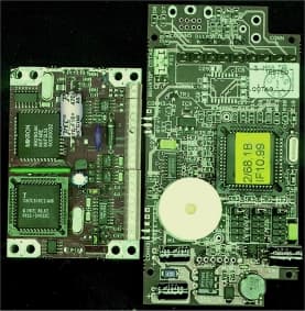
Click to zoom
Application Details
- Equipment Class
- DSR - Part 15 Remote Control/Security Device Transceiver
- Date of Grant
- Sep 26, 2000
- Application Purpose
- Original Equipment
- Date of Application
- Aug 06, 2000
- Equipment Note
- Contactless Smartcard Reader
- Frequency Range
- 40.66000000 - 40.77000000
- Company
- Bewator Ltd.
- Country
- Sweden
Documents & Files
Document Text
Text extracted from the exhibit documents filed with the FCC. Open a document above to read the original.
Users Manual
IN107 - Issue 1A January 2000 - Page 1 of 2 Installation Note SM501 Contactless Smartcard Reader and SM501K Contactless Smartcard and PIN Reader IN107 Mounting, connecting and setting up Mount the Reader in a suitable position near the door approximately 1.2m from the floor. The Reader can be installed outside in a sheltered position. The Reader has a mounting plate with two oval mounting holes which are suitable for most installations - you first need to break open the mounting holes using a screwdriver. There are also four round holes in the mounting plate which will align with a standard wall box of the type used, for example, for light switches. 1.If the Reader is fixed to the mounting plate, undo the four screws which are in each corner, then place the mounting plate in position on the wall or door frame and mark the position of the two mounting holes. Note: the mounting plate must be positioned with its connector at the top left. 2.Drill the two mounting holes. The holes accept 3.5mm machine screws or No 6 wood screws. 3.The connections are made to the connector on the mounting plate. Pass the cable through the large hole in the centre of the mounting plate. Note: the two power supply cables must be passed twice through the hole in the ferrite bead supplied with the Reader before they are joined to the connector, as shown in the following diagram: - + from power supply each cable passes through ferrite bead twice 0V V+ to connector on mounting plate 4.Make the connections shown in the following table as required: NameFunction V+Power supply +V (+ve) unregulated DC max 36.0V, min 10.0V, 250mA max 0VPower supply 0V (-ve), (also ground reference for data output) AmberEither: Amber LED control - 0V for amber LED Or: BCLINK data interface Rx HornHorn - 0V to sound RedEither: Red LED control - 0V for red LED Or: BCLINK data interface address GreenEither: Green LED control - 0V for green LED Or: Single wire LED control 0V for green LED, +5V for red LED (0V also switches off amber LED) D0Data zero for Wiegand output Data for Mag Stripe output BCLINK data interface Tx D1Data one for Wiegand output Clock for Mag Stripe output DAData Available for Wiegand or Mag Stripe output IN107 - Issue 1A January 2000 - Page 2 of 2 Note: do not apply a voltage greater than +5V to the horn input or the LED inputs 4.Route the cable tidily, then screw the mounting plate to the wall or door frame. Make sure all braid and loose filaments of wire are cut right back or insulated with tape or sleeving. 5.Set the jumpers on the Reader to provide the functions you require, as described in the following tables: INTERFACE Jumper JU1Function 132 bit Wiegand 234 bit Wiegand 310 character Mag Stripe 426 bit Wiegand 537 character Mag Stripe DATA Jumper JU2Function 1Read chip serial number from any Mifare card 2Read Girovend information only from Girovend cards 3Read Cotag information only from Cotag cards 4not used 5not used LED CONTROL Jumper JU3Function 1Internal - LED and horn inputs are disabled 2Single wire LED control - 0V on GREEN input for green LED, +5V on GREEN input for red LED 3External - LEDs and horn can be controlled using the RED, GREEN, AMBER and HORN inputs - 0V to activate 5BCLINK 6.Locate the Reader on the mounting plate with the LEDs at the top left and press it home - the Reader cannot be pushed fully home unless it is the correct way round. 7.Tighten the screws, then insert the little plastic plugs supplied with the Reader into the screw-holes so that the screws cannot be seen and the case looks neat. (Note that the plastic plugs cannot be removed without damaging them - four spare plugs are supplied with each Reader.) 8.Power up the Reader and test it: hold a smart card close to the outline of the card engraved on the face of the Reader - the Reader should bleep when the card is read and the host should receive the card data output. Each key-press should give an amber flash and the host should receive PIN data. For more information on the SM501 and SM501K Readers, please see the Handbook HB02/104. FCC Statement This device complies with part 15 of the FCC Rules. Operation is subject to the following two conditions: 1) This device may not cause harmful interference, and 2) This device must accept any interference received, including interference that may cause undesired operation.
Users Manual
SM501 and SM501K Contactless Smartcard Reader Handbook HB02/104 Iss 1A Applicability This handbook applies to the SM501 and SM501K Contactless Smartcard Readers © BEWATOR COTAGJANUARY 2000 This handbook is based on the best information available to Bewator Cotag at the time of publication. Although every effort is made to keep our documentation up to date, small changes which arise from the Company's policy of continuing product improvement are not necessarily incorporated. Some products are not available in all countries. All orders are accepted only on the Company's standard Conditions of Sale, copies of which are available on request. Bewator Cotag, a division of Bewator Group Ltd, Mercers Row, Cambridge CB5 8EX, UK Tel: +44 (0)1223 321535 Fax: +44 (0)1223 366799 Email: [email protected] www.bewator-cotag.com i Contents Chapter 1 Introduction Data output ............................................................................................. 1-1 Reading Smartcard data ........................................................................... 1-1 Setting up the Reader............................................................................... 1-1 Chapter 2 Installing Mounting, connecting and setting up ........................................................ 2-1 Chapter 3 Setting up Jumper settings ....................................................................................... 3-1 Distributor Code ...................................................................................... 3-1 Interface 5 ............................................................................................... 3-1 Data output selection (jumper JU1) .......................................................... 3-2 Data type selection (JU2).......................................................................... 3-3 Data output in “chip serial number” mode ................................................ 3-3 Interface 1 ...................................................................................... 3-3 Interface 2 ...................................................................................... 3-3 Interface 3 ...................................................................................... 3-3 Interface 4 ...................................................................................... 3-4 Interface 5 ...................................................................................... 3-4 Data output in “Girovend” mode ............................................................... 3-4 Interface 1 ...................................................................................... 3-4 Interface 2 ...................................................................................... 3-5 Interface 3 ...................................................................................... 3-5 Interface 4 ...................................................................................... 3-5 Interface 5 ...................................................................................... 3-5 Data output in “Cotag” mode .................................................................... 3-6 Interface 1 ...................................................................................... 3-6 Interface 2 ...................................................................................... 3-6 Interface 3 ...................................................................................... 3-6 Interface 4 ...................................................................................... 3-6 Interface 5 ...................................................................................... 3-7 LED control and BCLINK selection (JU3)................................................... 3-7 LED control .................................................................................... 3-7 BCLINK .......................................................................................... 3-8 Chapter 4 Operation LEDs ....................................................................................................... 4-1 Internal LED control ....................................................................... 4-1 Single wire LED control ................................................................... 4-1 External LED control....................................................................... 4-2 All LED control modes..................................................................... 4-2 Horn ........................................................................................................ 4-2 PIN data................................................................................................... 4-2 Using cards.............................................................................................. 4-2 Looking after a card ........................................................................... 4-2 SM501 and SM501K Contactless Smartcard Reader ii Hold off time ............................................................................................ 4-3 Repeat Data Delay (RDD).......................................................................... 4-3 Chapter 5 Data output Electrical characteristics of outputs from the Reader ................................. 5-1 Data Hold input ....................................................................................... 5-2 Wiegand interface..................................................................................... 5-2 Connections....................................................................................... 5-2 Electrical characteristics .................................................................... 5-2 Data format ....................................................................................... 5-2 Card data ....................................................................................... 5-3 PINpad data................................................…
Text truncated - open the document above for the full version.
Block Diagram
Bewator CotagFCC ID: EZO5PQ-SM500 SmartCard Reader: General Layout FS1 JU 1 JU 2 JU 3 GEMPLUS 680 INTERFACE BOARD BEWATOR COTAG ASIC 13.56MHz 14.74MHz 80C524 μP 2/68 1B or later 8 MHz Screen 0v + V +V 0V hold Amber Red Green D0 D1 DA Tx Rx
Cover Letter(s)
Bewator Cotag A DIVISION OF BEWATOR GROUP LIMITED Me rce rs Row, Cambridge, CB5 8EX UK Tel: 01223 472300 Fax: 01223 366799 Federal Communications Commission Date: 8 th August 2000 Equipment Authorization Division Application Processing Branch, 7435 OAKLAND MILLS ROAD COLUMBIA, MD 21046 Form 731 Confirmation No EA98396 FCC ID: EZO5PQ SM500: Contactless Smartcard Reader Dear Sir/ Madam I hereby apply for Certification for the above SM500 Contactless Smartcard Reader under Part 15 of the FCC Rules and present the follow ing documentation for your attention: 1. Introduction and outline drawing 2. Description of device, labels, and circuit block diagram 3. Test Report from dB Technology No R1238 4. Items List 5. Installation notes If you have any problem w ith this submission please contact me, Martin Young at Bew ator-Cotag, Cambridge, England Fax: 44-1223-366799 e-mail address: [email protected] yours faithfully, Martin J D Young Quality & Approvals Engineer The SM500 series Contactless Smartcard Reader FCC ID: EZO5PQ SM500 Bewator Cotag2 Introduction: The Contactless Smartcard reader is designed to read codes contained in "Mifare" smartcards and to pass these codes to a host system. The SM500 reader provides a choice of Wiegand, Mag Stripe or BC link data output, selected by jumper. The reader consists of a printed circuit assembly, with or without a keypad, mounted inside a plastic enclosure. Power supply: 10 to 24v DC. 100mA. 123 456 789 * 0# 120 mm SM500 SERIES CONTACTLESS SMARTCARD READER 120 mm SM501K has integrated keyboard (see drawing below) SM501 has same dimensions but without keyboard FCC ID: EZO5PQ SM500 Bewator Cotag3 Functional Description of operation of SM500 series Smartcard readers The smartcard reader consists of two parts; namely the Gemplus Micro680 smartcard reader module that carries out secure RF transactions with a Smartcard and an interface and power supply PCA which takes the data read from the card and converts it into a suitable form to be output via three open drain outputs. The host system then makes a judgement as to the validity of the card using the data supplied from the reader and pinpad and indicates the result by asserting one or more of the four inputs to the reader, the reader then reflects the state of these inputs on the three LEDs and the horn. Block diagram Power Supply: JU1 is used to select upper or lower voltage ranges, nominally 10 to 35 V dc and 4 to 15.6 V dc. The output voltage has been chosen to be 13.8 V, which is as high as possible within the tolerance limits, in order to reduce the heatsink requirements on reg 2. Transmitter: The 13.56MHz is derived from the Xtal. The Mifare smartcard divides this by 16 to give the card output frequency of 847kHz. 456 789 *0# 123 Micro680 module Microprocessor Smart card 10V regulator 5V regulator Connection to host Power supply 10V-36V 100mA Filter Indicator LEDs Horn TTL RS232 c o mms l i nk RF to/from card FCC ID: EZO5PQ SM500 Bewator Cotag4 FCC Labelling: 1. The FCC disclaimer label is featured in the Installation Note attached, since the reader is not sufficiently large to display the label itself. This device complies with part 15 of the FCC Rules. Operation is subject to the following two conditions: (1) This device may not cause harmful interference, and (2) this device must accept any interference received, including interference that may cause undesired operation. 2. Identification label on the back of the reader: FCC ID: EZO5PQ SM500 BEWATOR COTAG CAMBRIDGE UK ETS 300-330 WT LICENCE EXEMPT Model No SM501K Type SM500 Reader Serial No XXXX VOLTS 10 to 36 AC - DC : DC Amps: 100mA
ID Label/Location Info
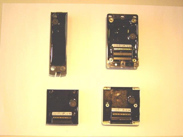
FCC ID: EZO5PQ-SM500Bewator Cotag Contactless Smartcard Reader FCC Labelling: Photograph of inside back cover as mounted for installation, showing FCC labels actual size of back cover: 120 mm x 120 mm • please note: the cover is the same for both keypad unit P02-488 shown above and non- keypad unit P02-487 (not shown) FCC ID: EZO5PQ-SM500Bewator Cotag Contactless Smartcard Reader upper drawing: P02-447 (with keypad) label lower drawing: P02-448 (no keypad) label PRINTING NOTES: 1. All text and graphics to be black on a white background. 2. Print using a BRADY BP4000 Printer and software or similar. 3. Use computer file reference \1367 4. Serial No added at final assembly. FCC ID: EZO5PQ-SM500 ETS 300-330 WT LICENCE EXEMPT Type: SM500 Reader VOLTS 10 to 36 DC Max Current 100mA Model No SM501K Part No P02-447 BEWATOR COTAG Serial No CAMBRIDGE UK FCC ID: EZO5PQ-SM500 ETS 300-330 WT LICENCE EXEMPT Type: SM500 Reader VOLTS 10 to 36 DC Max Current 100mA Model No SM501 Part No P02-448 BEWATOR COTAG CAMBRIDGE UK Serial No 50 mm 38mm
Internal Photos
EZO5PQ-SM500 SM500 CONTACTLESS SMARTCARD READER TYPE SM500 PROMOTIONAL PHOTOGRAPH : SM501K leftSM501 right Bewator CotagFCC ID: EZO5PQ-SM500 PCA: top view: (common to SM501 and SM501K) Gemplus Micro 680 PCA left: Reader Interface PCA right view dimensions: 4.5 inches square
Parts List/Tune Up Info
Bewator-Cotag Smartcard Reader Interface PCAIL02-446 Issue 3 Drawn MDS Date 26 Oct 99Issue Date Item Ident M.I.DescriptionQt yUnits Part No.VarRemarks 1 Smartcard Programmer PCB1 A02-467 2 - 3 Surface Mount Com ponents - 4 - 5FS1 250mA Fuse in SM Holder1 G142 6 - 7X1 8MHz +/-50PPM Crystal1 X111 8 - 9IC2 5V Regulator LM78L05ACM1 J222 10IC6 LM2901M Quad Comparator SM SO14 1 N151 11IC7 68HC711E9 SM QFJ521 M02-68-xx Fit in socket Item 94. M172 programmed with SS02-68 issue 1B or later. 12IC8 Not fitted - 13IC9 2M33164 4.3v Voltage Monitor SOT223 1 N150 14 - 15TR1 NDS0605 P Channel MOSFET SM SOT23 2 J219 16TR2 NDS7002A N-Channel MOSFET SM SOT23 4 J202 17TR3 NDS7002A N-Channel MOSFET SM SOT23 - J202 18TR4 NDS7002A N-Channel MOSFET SM SOT23 - J202 19TR5 NDS7002A N-Channel MOSFET SM SOT23 - J202 20TR6 NDS0605 P Channel MOSFET SM SOT23 - J219 21 - 22 - 23D1 42V Transient Suppressor SM 1206 1 J221 24D2 B230 Schotty Diode smt1 J214 25D3 5.6V Transient Suppressor SM 0805 7 J197 26D4 5.6V Transient Suppressor SM 0805 - J197 27D5 5.6V Transient Suppressor SM 0805 - J197 28D6 5.6V Transient Suppressor SM 0805 - J197 29D7 5.6V Transient Suppressor SM 0805 - J197 30D8 5.6V Transient Suppressor SM 0805 - J197 31D9 5.6V Transient Suppressor SM 0805 - J197 32 - 33 - IL446 Iss3Page 1 Bewator-Cotag Item Ident M.I.DescriptionQt yUnits Part No.VarRemarks 34L1 47μH ±10% Inductor SM 18121 Q137 35L2 330μH+-10%Inductor SM1 Q139 36 - 37C3 3n3+-10% 50v SM X7R 08051 C345 38 - 39C5 10uF +-10% 16VDC Tantalum SM 1 C332 40C17 22pF +-5% 50v SM COG 0805 NB 2 C298 41C18 22pF +-5% 50v SM COG 0805 NB - C298 42C21 100nF +-10% 50v SM X7R 0805 NB 3 C306 43C22 100nF +-10% 50v SM X7R 0805 NB - C306 44C23 22uF +/- 10% 10VDC Tantalum SM 1 C333 45C24 100nF +-10% 50v SM X7R 0805 NB - C306 46C25 Not fitted - 47C26 Not fitted - 48C27 Not fitted - 49C28 Not fitted - 50C29 Not fitted - 51 - 52 - 53R1 1K +-5% 0.1W 0805 SM NB9 R309 54R2 5K6+-5% 0.125W 0805 SM1 R350 55R3 1K +-5% 0.1W 0805 SM NB- R309 56R4 2K2 +/-1% 0.1W 0805 SM3 R343 57R5 2K2 +/-1% 0.1W 0805 SM- R343 58R6 2K2 +/-1% 0.1W 0805 SM- R343 59R7 Not fitted - 60R8 1K +-5% 0.1W 0805 SM NB- R309 61R9 10K +-5% 0.1W 0805 SM NB17 R306 62R10 10K +-5% 0.1W 0805 SM NB- R306 63R11 10K +-5% 0.1W 0805 SM NB- R306 64R12 10K +-5% 0.1W 0805 SM NB- R306 65R13 10K +-5% 0.1W 0805 SM NB- R306 66R14 10K +-5% 0.1W 0805 SM NB- R306 67R15 10K +-5% 0.1W 0805 SM NB- R306 68R16 10K +-5% 0.1W 0805 SM NB- R306 69R17 10K +-5% 0.1W 0805 SM NB- R306 70R18 10K +-5% 0.1W 0805 SM NB- R306 71R19 10K +-5% 0.1W 0805 SM NB- R306 72R30 10M +-5% 0.1W 0805 SM NB1 R302 73R34 1K +-5% 0.1W 0805 SM NB- R309 74R35 1K +-5% 0.1W 0805 SM NB- R309 75R36 1K +-5% 0.1W 0805 SM NB- R309 76R37 100K +-5% 0.1W 0805 SM NB 10 R329 77R38 10K +-5% 0.1W 0805 SM NB- R306 78R39 10K +-5% 0.1W 0805 SM NB- R306 79R40 10K +-5% 0.1W 0805 SM NB- R306 IL446 Iss3Page 2 Bewator-Cotag Item Ident M.I.DescriptionQt yUnits Part No.VarRemarks 80R41 100K +-5% 0.1W 0805 SM NB- R329 81R44 100K +-5% 0.1W 0805 SM NB- R329 82R45 100K +-5% 0.1W 0805 SM NB- R329 83R46 100K +-5% 0.1W 0805 SM NB- R329 84R47 100K +-5% 0.1W 0805 SM NB- R329 85R48 100K +-5% 0.1W 0805 SM NB- R329 86R49 100K +-5% 0.1W 0805 SM NB- R329 87R50 100K +-5% 0.1W 0805 SM NB- R329 88R52 1K +-5% 0.1W 0805 SM NB- R309 89R53 1K +-5% 0.1W 0805 SM NB- R309 90R57 10K +-5% 0.1W 0805 SM NB- R306 91R58 10K +-5% 0.1W 0805 SM NB- R306 92R59 10K +-5% 0.1W 0805 SM NB- R306 93R62 1K +-5% 0.1W 0805 SM NB- R309 94R63 100K +-5% 0.1W 0805 SM NB- R329 95 - 96 - 97 - 98 PLCC Socket 52 Way PCB SMT Y353 99 - 100 - 101 - 102 - 103 - 104 Through Hole and Other Components - 105 - 106IC1 LM2594-ADJ Regulator1 J220 107 - 108C1 47μF+-20% 50v Axial Elect2 C344 109C2 47μF+-20% 50v Axial Elect- C344 110C4 100μF +/-20% 50Vdc Al.Elect Radial 1 C346 111 H1A 3-24V 5mA@12V [email protected] Sounder 1 E116 112 - 113J1 Jumper Pin 9 Way PCB Mt30 Y189 114J2 Jumper Pin 9 Way PCB Mt- Y189 115J3 Jumper Pin 9 Way PCB Mt- Y189 116 0.1" Pitch Jumper 2 Way3 Y190 117 - 118 CON N1 Plug-In Connector Pins9 Y244 Modify to Drawing D02-1371 119 - IL446 Iss3Page 3 Bewator-Cotag Item Ident M.I.DescriptionQt yUnits Part No.VarRemarks 120 CON N3 SIL Edge Pins5 Y355 Cut to 3 Way and 2 Way 121 - 122 - 123 D10 Red LED1 L157 On Reverse 124 D11 Green LED1 L158 On Reverse 125 D12 Yellow LED1 L159 On Reverse 126 3 Way LED Spacer1 L160 On Reverse. Cut 12 way into 4 x 3 way. 127 - 128 CON N4 Not fitted - 129 CON N5 Not fitted - IL446 Iss3Page 4
Test Report
|---------- ( Cambridge Ltd. ) ----------| Testing EMCEMC Consultancy EMC Training or : 01223 241140 (accounts) 23, Headington Drive, Cambridge. CB1 4HE Tel : 01954 251974 (test site) Fax : 01954 251907 email: [email protected] web : www.dbtechnology.mcmail.com REPORT ON ELECTROMAGNETIC COMPATIBILITY TESTS Performed at: TWENTY PENCE TEST SITE Twenty Pence Road, Cottenham, Cambridge U.K. CB4 4PS on BEWATOR-COTAG SM500 Contactless SmartCard Reader dated 14 March 2000 1 of 25 Page: Test Report T0140 Test No: FCCID: EZO5PQ SM500 R1238 Report No: dB Technology (Cambridge) Ltd. Equipment Under Test (EUT):SM500 Test Commissioned by:BEWATOR-COTAG Mercers Row Newmarket Road Cambridge CB5 8EX Representative:Martin Young Test Started:6 March 2000 Test Completed:13 March 2000 Test Engineer:Dave Smith Date of Report:14 March 2000 Report: Written by:Dave Smith Checked by:Derek Barlow Date:14 March 00Date:24 March 00 Test Standards Applied CFR 47 : 1998 Code of Federal Regulations: Part 15 Subpart C - Radio Frequency Devices - PASS Intentional Radiators 2 of 25 Page: Test Report T0140 Test No: FCCID: EZO5PQ SM500 R1238 Report No: dB Technology (Cambridge) Ltd. Emissions Test Results Summary CFR 47 : 1998PASS TestPortMethodLimitPASS/FAILNotes Conductedac powerANSI C63.4:1992FCC pt 15PASS Emissions Subsection C Radiated ANSI C63.4:1992FCC pt 15PASS #1 Emissions Subsection C #1The limits of section 15.225 (13.553 - 13.567MHz) and section 15.229 (40.66 - 40.70 MHz) were applied, based on the manufacturer’s declared operating frequencies. 3 of 25 Page: Test Report T0140 Test No: FCCID: EZO5PQ SM500 R1238 Report No: dB Technology (Cambridge) Ltd. Contents 25 PLOT 10 Radiated Emissions 250MHz to 1GHz - SmartCard not in Field ....................... 24 PLOT 9 Radiated Emissions 25MHz to 275MHz - SmartCard not in Field ....................... 23 PLOT 8 Radiated Emissions 250MHz to 1GHz - SmartCard in Field ........................... 22 PLOT 7 Radiated Emissions 25MHz to 275MHz - SmartCard in Field .......................... 21 PLOT 6 Radiated Emissions below 30MHz - SmartCard not in Field ........................... 20 PLOT 5 Radiated Emissions below 30MHz - SmartCard in Field .............................. 19 PLOT 4 Conducted Emissions (Neutral) - SmartCard not in Field ............................. 18 PLOT 3 Conducted Emissions (Neutral) - SmartCard in Field ................................. 17 PLOT 2 Conducted Emissions (Live) - SmartCard not in Field ................................ 16 PLOT 1 Conducted Emissions (Live) - SmartCard in Field ................................... 15 4.3 Radiated Emissions Results - Spurious Emissions ....................................... 14 4.2 Radiated Emissions Results - Intentional Emissions ...................................... 13 4.1 Conducted Emission Results .......................................................... 12 4 Test Results ......................................................................... 11 3.3 Radiated Emissions above 30MHz ..................................................... 11 3.2 Radiated Emissions below 30MHz ..................................................... 11 3.1 Conducted Emissions - ac power ...................................................... 11 3 Test Methods ........................................................................ 10 2 Test Equipment ...................................................................... 9 Photograph 4 Radiated Emissions - Back ................................................... 9 Photograph 3 Radiated Emissions - Front .................................................. 8 Photograph 2 Conducted Emissions - Front ............................................... 8 Photograph 1 Conducted Emissions - Back ................................................. 7 Figure 1 General Arrangement of EUT and Peripherals ....................................... 6 1.3 EUT Operating Modes ................................................................ 5 1.2 Modifications to EUT and Peripherals ................................................... 5 1.1 General ............................................................................. 5 1 EUT Details ........................................................................... 4 of 25 Page: Test Report T0140 Test No: FCCID: EZO5PQ SM500 R1238 Report No: dB Technology (Cambridge) Ltd. 1 EUT Details 1.1 General The EUT was a SM500 Contactless SmartCard Reader. The EUT is an intentional radiator operating in both of the following bands: o13.553 - 13.567MHz (Section 15.225) o40.66 - 40.70 MHz (Section 15.229) The EUT contained no clocks or circuitry operating at or above 108MHz. Details of the EUT and associated peripherals used during the tests are listed below. Figure 1 shows the interconnections between the EUT and peripherals. ItemManufacturerModelDescriptionSerial No:FCC ID 1Bewator-CotagSM500EUT0012EZO5PQSM500 2ARCHER273-1652AAC adaptor 3Bewator-Cotag4000Controller1203EZO5PQ4000 with PSU 1.2 Modifications to EUT and Peripherals Details of any modifications that were required to achieve compliance are listed below. The modification numbers are referred to in the results sections as appropriate. ModDetails No: 0 Original unit with no modifications. 5 of 25 Page: Test Report T0140 Test No: FCCID: EZO5PQ SM500 R1238 Report No: dB Technology (Cambridge) Ltd. 1.3 EUT Operating Modes The EUT was tested in the following operating mode or modes. Generally, operating modes are chosen that will exercise the functions of the EUT as fully as possible and in a manner likely to produce maximum emission levels or susceptibility. Individual test result sheets reference the operating mode of the EUT. OperatingDetails Mode 1 SmartCard in Field - Sending data to controller. 2 SmartCard not in Field. 6 of 25 Page: Test Report T0140 Test No: FCCID: EZO5PQ SM500 R1238 Report No: dB Technology (Cambridge) Ltd. Figure 1 General Arrangement of EUT and Peripherals SM500 4000 Controller AC PSU 115…
Text truncated - open the document above for the full version.
Contact Information
Applicant
Christer Liedholm(Vice President, Operations)
Technical Contact
Bewator-CotagMartin J Young
[email protected]44-1223-472352
Bewator-Cotag · Cambridge · United Kingdom
Non-Technical Contact
Bewator-CotagMartin J Young
[email protected]44-1223-321535
Test Firm
DB TechnologyDave Smith
Technical Specifications
| # | Rule Parts | Frequency Range | Power Output | Tolerance |
|---|---|---|---|---|
| 2 | - | 40.66 MHz - 40.77 MHz | - | ppm |
Other Applications from Bewator Ltd.
EZO5PQXX500
Jul 13, 2004xx500 Series Readers
Equipment Class
DCD - Part 15 Low Power Transmitter Below 1705 kHzEZO5PQ5290
Jan 27, 1998Tag Reader Transmitter
Equipment Class
DCD - Part 15 Low Power Transmitter Below 1705 kHzEZO5PQ4010
Nov 27, 1997Store Security Device
Equipment Class
DCD - Part 15 Low Power Transmitter Below 1705 kHzEZO5PQ4000
Jul 27, 1993DCD - Part 15 Low Power Transmitter Below 1705 kHz
Equipment Class
DCD - Part 15 Low Power Transmitter Below 1705 kHz