EZO5PQXX500xx500 Series Readers
Bewator Ltd.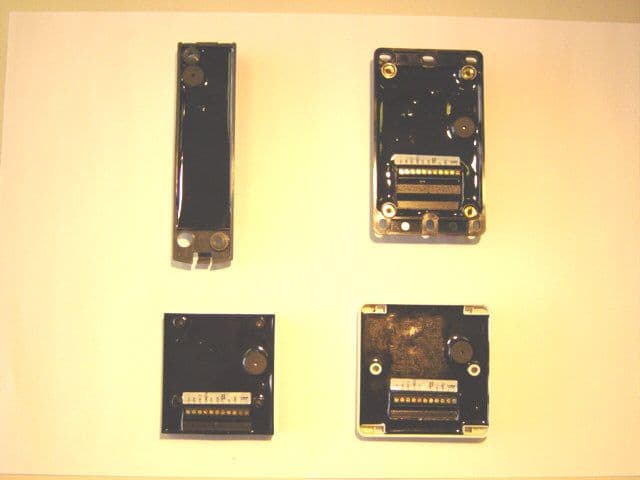
Click to zoom
Application Details
- Equipment Class
- DCD - Part 15 Low Power Transmitter Below 1705 kHz
- Date of Grant
- Jul 13, 2004
- Application Purpose
- Original Equipment
- Date of Application
- Feb 18, 2004
- Equipment Note
- xx500 Series Readers
- Frequency Range
- 0.13100000 - 0.13300000
- Company
- Bewator Ltd.
- Country
- Sweden
Documents & Files
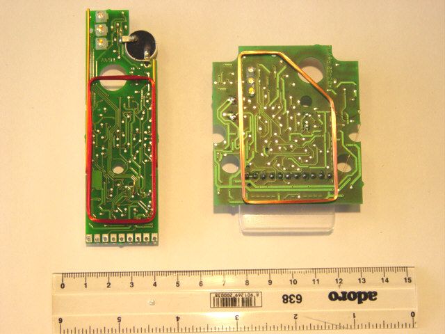
Document Text
Text extracted from the exhibit documents filed with the FCC. Open a document above to read the original.
Users Manual
Proximity Readers Handbook HB00117 Issue 1 Applicability This handbook applies to the PR500 Proximity Reader, the HD500-2 Heavy Duty Proximity Reader, the SP500 Switch Plate Proximity Reader and the PM500 Panel Mount Proximity Reader © BEWATOR LTDJULY 2003 This handbook is based on the best information available to Bewator at the time of publication. Although every effort is made to keep our documentation up to date, small changes which arise from the Company's policy of continuing product improvement are not necessarily incorporated. Some products are not available in all countries. All orders are accepted only on the Company's standard Conditions of Sale, copies of which are available on request. Bewator Ltd, Albany Street, Newport, South Wales, NP20 5XW, UK Tel: +44 (0)1633 821000 Fax: +44 (0)1633 850893 Email: [email protected] Website: www.bewator.co.uk NOTE: This equipment has been tested and found to comply with the limits for a Class B digital device, pursuant to part 15 of the FCC Rules. These limits are designed to provide reasonable protection against harmful interference in a residential installation. This equipment generates, uses and can radiate radio frequency energy and, if not installed and used in accordance with the instructions, may cause harmful interference to radio communications. However, there is no guarantee that interference will not occur in a particular installation. If this equipment does cause harmful interference to radio or television reception, which can be determined by turning the equipment off and on, the user is encouraged to try to correct the interference by one or more of the following measures: - Reorient or relocate the receiving antenna. - Increase the separation between the equipment and the receiver. - Connect the equipment into an outlet on a circuit different from that to which the receiver is connected. - Consult the dealer or an experienced radio/TV technician for help. Safety This equipment must be powered by a supply which is suitably insulated from the mains. The supply should be classed as SELV under the terms of EN60950. The power supply must be connected to safety earth. A mains isolation switch should be provided by the installer. Any third party equipment connected must also be suitably insulated from the mains supply. Any fuses which are replaced must be of the recommended rating and type. Wiring connected by the installer must be adequate. The use of inadequate wiring may present a fire hazard. Except where specified the equipment is not suitable for outside use. Except where specified this equipment is not for use in safety critical applications. i Contents Chapter 1 Introduction Reader types ............................................................................................1-1 Data output .............................................................................................1-1 Interrogation of cards and tags .................................................................1-2 Setting up the Reader...............................................................................1-2 Chapter 2 Installing and connecting PR500-2 Proximity Reader........................................................................2-1 HD500-2 Heavy Duty Proximity Reader.....................................................2-3 SP500 Switch Plate Proximity Reader........................................................2-6 PM500 Panel Mount Proximity Reader ......................................................2-8 Configuring and testing the Reader...............................................2-10 Chapter 3 Setting up Configuring the Reader.............................................................................3-1 The configuration card .............................................................................3-1 The DC/SC card ......................................................................................3-2 Programming the configuration card .........................................................3-2 0xxs (secondary code swap) 3-2 xbff (ASCII interface protocol and baud rate).....................................3-3 xxxh (Data Hold input signal polarity) ................................................3-3 xxhe (horn configuration) 3-4 hhhh (hold-off time) ........................................................................3-4 pxxx (calculation of leading parity bit for 26-bit Wiegand interfaces)....3-5 xxrg (internal/external control ofred and green LEDs) ........................3-5 crrrrrrr (Secondary Code check disable, and repeat data delay - RDD) .....................................................3-6 iiiiiiii (interface number) 3-6 Note to existing users of PR500 and HD500 ....................................3-6 Programming the DC/SC card ..................................................................3-7 Presenting configuration card and DC/SC card to the Reader ....................3-7 Changing the Secondary Code or Distributor Code ....................................3-7 Examples of working out what to program into the configuration card in 63-bit mode on the Programmer ...............................3-8 Example 1.........................................................................................3-8 Example 2.........................................................................................3-9 Proximity Readers Handbook ii Chapter 4 Data interfaces Electrical characteristics of outputs from the Reader .................................4-1 Data Hold input .......................................................................................4-2 Wiegand ..................................................................................................4-2 Connections ......................................................................................4-2 Electrical characteristics....................................................................4-2 Data format......................................…
Text truncated - open the document above for the full version.
Attestation Statements
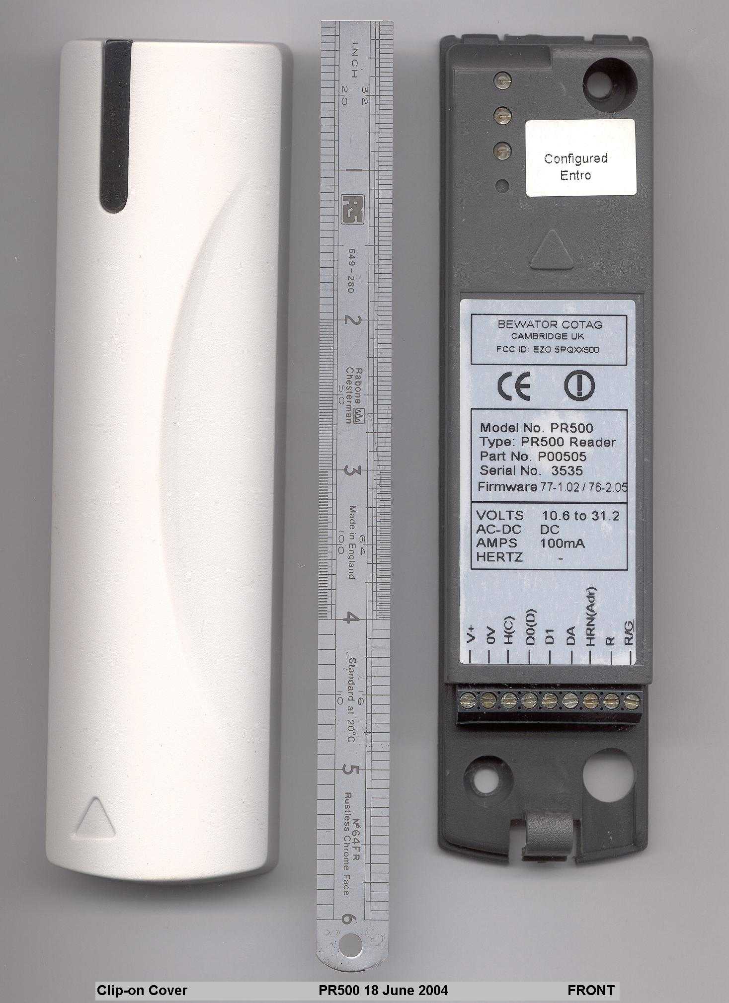
IN00119 - Issue 6 July 2003 - Page 1 of 2 Installation Note PR500-GP Proximity Reader IN00119 The PR500 Reader must be connected to a power supply and to a host access control system. Removing the cover The Reader is supplied with the cover separate. If the cover has been fitted for any reason, remove it by pushing in the lug on its lower edge using a suitable screwdriver. Mounting and connecting 1. Choose a suitable position to mount the Reader near the door. The Reader has a maximum range of 30cm (12in) so it must be mounted in a position where the card or tag can easily be brought within this distance. We recommend it is mounted approximately one metre (3.5ft) above the ground. Also consider ease of access to the door once the card or tag has been read, for example, it is better to mount the Reader near the opening side of the door rather than the hinge side. 2. The Reader should be mounted with the LEDs at the top left. Mark out and drill the two mounting holes. Don’t fix the Reader to the wall yet. The holes accept 4mm machine screws or No 8 wood screws. 20 37.5 118 137.5 Fixing holes: 4.2 diameter Fixing Dimensions (mm) Cable entry hole 9mm diameter The cover overlaps the base slightly on all sides so you must allow a little extra room all round. 3. Route the cables into the Reader: you can use either the cut-out in the base or the one in the lower edge at the bottom of the Reader. IN00119 - Issue 6 July 2003 - Page 2 of 2 The connections required for the Reader are power supply connections (0V and +12V DC or +24V DC), data output connections for Wiegand or Magnetic Stripe (D0, D1, DA ) or ASCII/TTL ( H , D0, DA), and a connection from the host to the Data Hold input ( H ) if data lines from two Readers are to be connected in parallel. To promote EMC compliance we recommend you use 812 Cable as described here. Trim back and insulate the screens at the PR500. Connect the screens at the host only: do not connect any of the screens to the PR500. 4. When you have routed the cables into the Reader you can screw it to the wall. 5. Make the connections shown in the following table: Reader Function V+ Power supply +12V unregulated or 24V battery-backed* (absolute max 32V, min 10.6V, 100mA max) 0V Power supply 0V (-ve) (also ground reference for data output) H (C) “Data Hold” for Wiegand and Mag Stripe “CTS” for ASCII/TTL D0 (D) “Data Zero” for Wiegand “Data” for Mag Stripe “TXD” for ASCII/TTL D1 “Data One” for Wiegand “Strobe” for Mag Stripe DA “Data Available” for Wiegand “Present” for Mag Stripe “RTS” for ASCII/TTL Horn (Adr) Horn - 0V to sound, +5V to turn off R Red LED control - 0V for red LED R/G Single wire LED control 0V for green LED, +5V for red LED *The PR500 is designed to be operated by 12V unregulated power supplies, or 24V battery- backed power supplies. Operating voltage range is 10.6 to 32.0V. The upper voltage is intended to be compatible with the charging of 24V lead-acid batteries. Charge methods vary, and may be temperature dependent. 32V max is intended to be compatible with commonly used charging methods. If the upper operating voltage is exceeded then permanent damage may be caused. Installers and systems designers should check the max power supply voltage under all conditions. Do not operate the PR500 using unregulated 24V supplies. The PR500 current consumption can be significantly less than 100mA. The unloaded peak voltage from a nominal 24V unregulated supply will exceed the absolute max. 6. Do not fit the front cover to the Reader until you have configured it and tested it (see the Proximity Readers Handbook HB00117). In order to reduce paper waste we do not ship a handbook with this product. You can download a copy of this or any other handbook from our website: http://www.bewator.co.uk FCC Statement This device complies with part 15 of the FCC Rules. Operation is subject to the following two conditions: 1) This device may not cause harmful interference, and 2) This device must accept any interference received, including interference that may cause undesired operation.
Attestation Statements
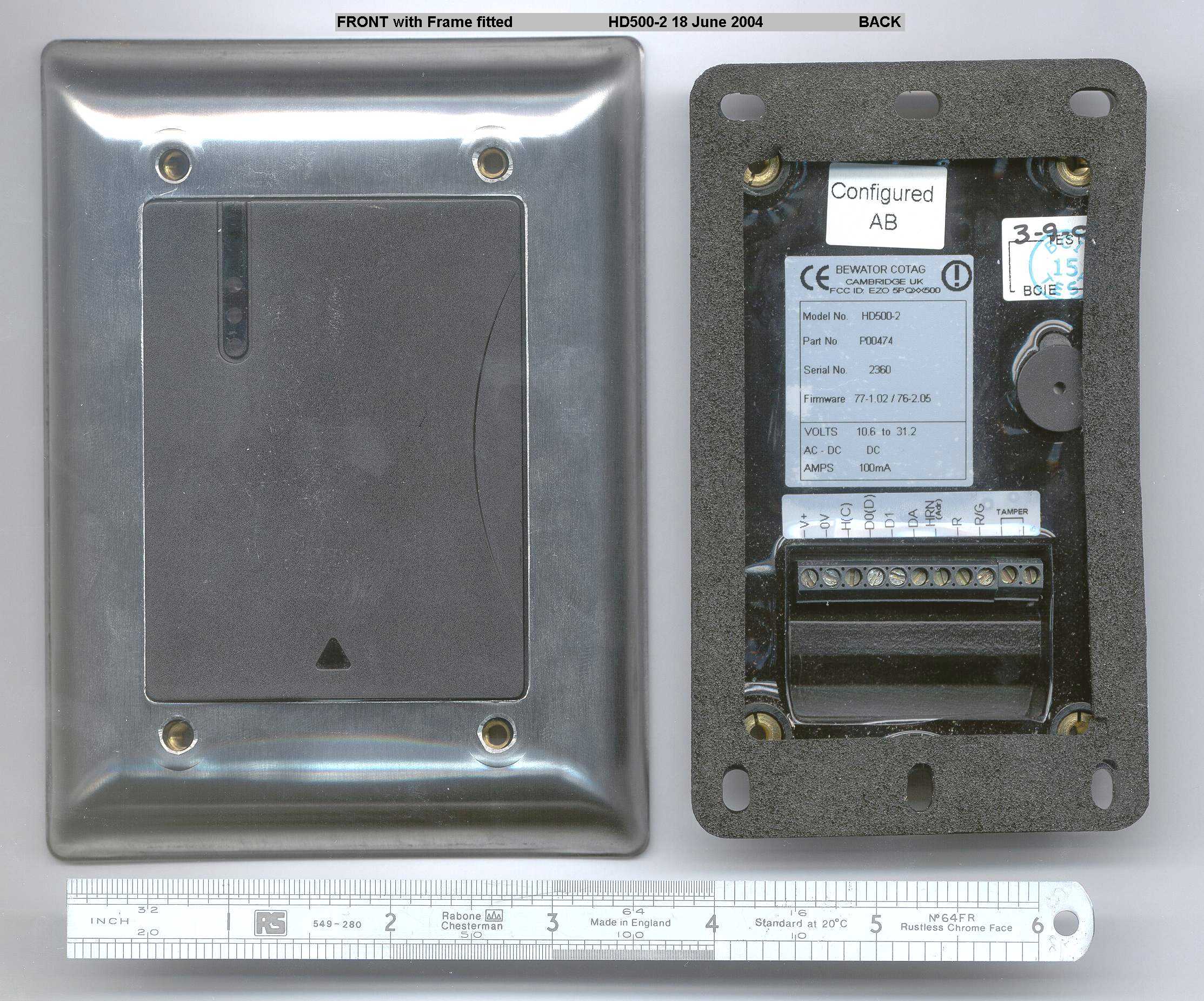
IN00125 - Issue 2 July 2003 - Page 1 of 3 Installation Note HD500-2-GP Heavy Duty Reader IN00125 The HD500-2 Reader must be connected to a power supply and to a host access control system. Mounting and connecting 1. Choose a suitable position to mount the Reader near the door. The Reader has a range of 5cm to 25cm (2in to 10in) dependent on the type of tag used, so it must be mounted in a position where the card or tag can easily be brought within this distance. We recommend it is mounted approximately one metre (3.5ft) above the ground. Also consider ease of access to the door once the card or tag has been read, for example, it is better to mount the Reader near the opening side of the door rather than the hinge side. 2. You can mount the Reader using any of the six mounting holes in the black plastic enclosure - the diagram at the back of this Installation Note shows the fixing dimensions and is drawn actual size so you can use it as a template when drilling the holes. The Reader should be mounted with the strip of LEDs at the top left. Note that you do not need the stainless steel frame when mounting the Reader - you fasten it to the Reader afterwards to prevent anyone undoing the mounting screws. 3. Mark out and drill the mounting holes, but don’t fix the Reader to the wall yet . The holes accept 4mm machine screws or No 8 wood screws. 4. The connections required for the Reader are power supply connections (0V and +12V DC or +24V DC), data output connections for Wiegand or Magnetic Stripe (D0, D1, DA) or ASCII/TTL (H, D0, DA), and a connection from the host to the Data Hold input (H) if data lines from two Readers are to be connected in parallel. To promote EMC compliance we recommend you use 812 Cable as described here. Trim back and insulate the screens at the HD500-2. Connect the screens at the host only: do not connect any of the screens to the HD500-2. IN00125 - Issue 2 July 2003 - Page 2 of 3 Route the cables into the Reader from behind, then make the connections shown in the table below. Reader Function V+ Power supply +12V unregulated or 24V battery-backed* (absolute max 32V, min 10.6V, 100mA max) 0V Power supply 0V (-ve) (also ground reference for data output) H (C) “Data Hold” for Wiegand and Mag Stripe, “CTS” for ASCII/TTL D0 (D) “Data Zero” for Wiegand, “Data” for Mag Stripe, “TXD” for ASCII/TTL D1 “Data One” for Wiegand, “Strobe” for Mag Stripe DA “Data Available” for Wiegand, “Present” for Mag Stripe, “RTS” for ASCII/TTL HRN (Adr) Horn - 0V to sound, +5V to turn off R Red LED control - 0V for red LED R/G Single wire LED control - 0V for green LED, +5V for red LED TAMPER Tamper circuit connection (hard wired link)# *The HD500-2 is designed to be operated by 12V unregulated power supplies, or 24V battery- backed power supplies. Operating voltage range is 10.6 to 32.0V. The upper voltage is intended to be compatible with the charging of 24V lead-acid batteries. Charge methods vary, and may be temperature dependent. 32V max is intended to be compatible with commonly used charging methods. If the upper operating voltage is exceeded then permanent damage may be caused. Installers and systems designers should check the max power supply voltage under all conditions. Do not operate the HD500-2 using unregulated 24V supplies. The HD500-2 current consumption can be significantly less than 100mA. The unloaded peak voltage from a nominal 24V unregulated supply will exceed the absolute max. #Two terminals are provided for use with a system 24hour tamper protection circuit. 5. Route the cable neatly then fix the Reader to the wall or door frame. 6. Do not fit the stainless steel frame to the Reader until you have configured it and tested it (see the Proximity Readers Handbook HB00117). 7. When you have configured the Reader and tested it to make sure that it is working correctly, you can fasten the Reader’s stainless steel frame using the four “Resistorx” M4x12 screws provided. These tamper- resistant screws can only be inserted or removed using the correct tool which is not supplied with the Reader: it can be obtained from Bewator Ltd as part number TX-20H. In order to reduce paper waste we do not ship a handbook with this product. You can download a copy of this or any other handbook from our website: http://www.bewator.co.uk FCC Statement This device complies with part 15 of the FCC Rules. Operation is subject to the following two conditions: 1) This device may not cause harmful interference, and 2) This device must accept any interference received, including interference that may cause undesired operation. IN00125 - Issue 2 July 2003 - Page 3 of 3 Mount the HD500-2 Reader in a suitable position near the door approximately 1m from the floor with the LEDs at the top left. You can fasten the Reader’s plastic case to the wall or door frame using any of the six mounting holes provided, as shown in the diagram below: Fixing Dimensions (mm) 6.5 106.5 119 6 629 58 70 Stainless steel frame: 100x128 7.555
Attestation Statements
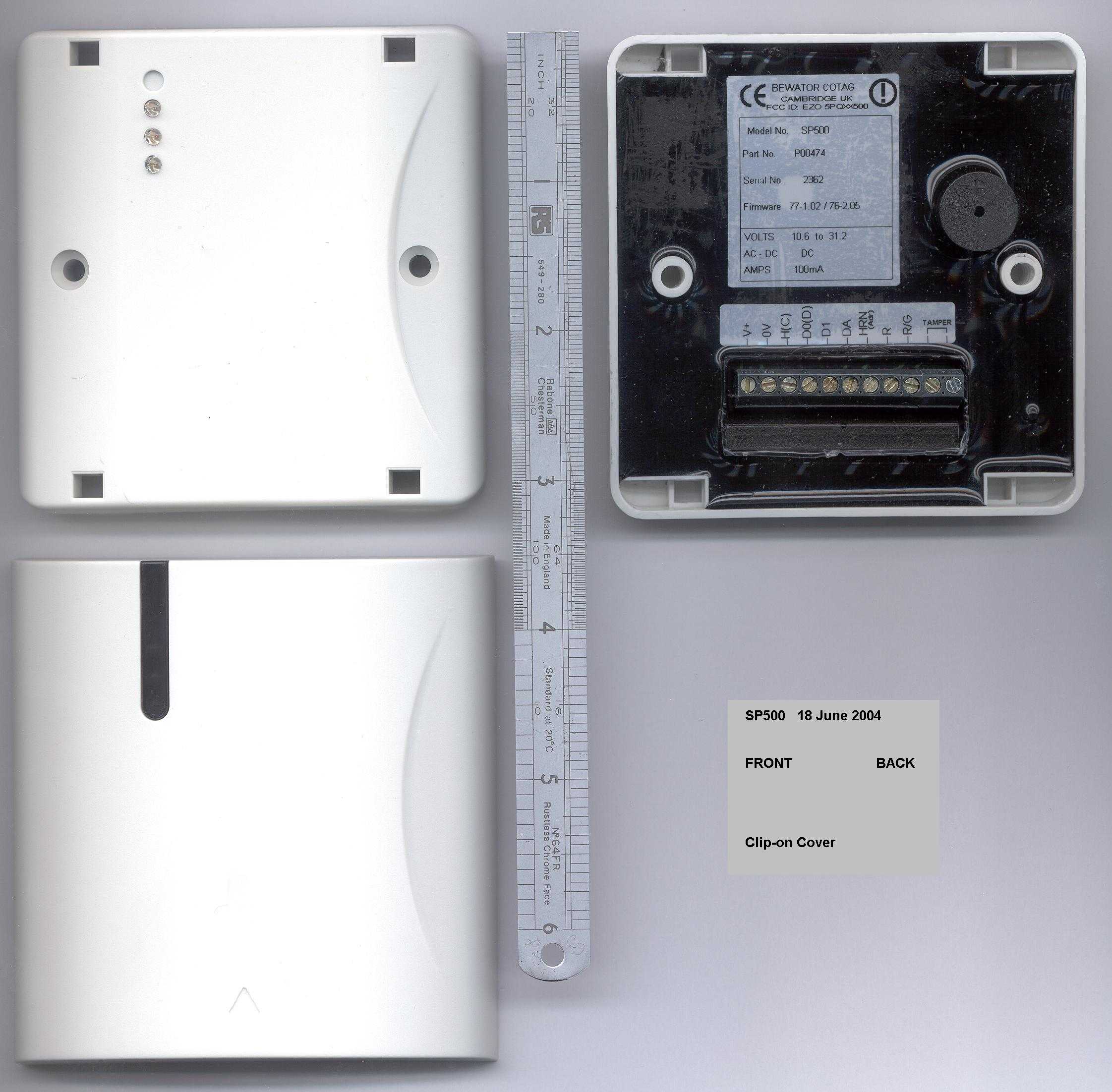
IN00126 - Issue 2 July 2003 - Page 1 of 2 Installation Note SP500-GP Switch Plate Reader IN00126 The SP500 Reader must be connected to a power supply and to a host access control system. Mounting and connecting 1. The SP500 Reader fits a standard single surface-mount or flush fitting back box, either metal or plastic, such as is used for light switches and mains plug sockets. The cover which clips onto the front of the Reader is 86mm square, so remember when you install the back box to leave enough clearance around it to fit the cover. The Reader has a range of 5cm to 30cm (2in to 12in) dependent on the type of tag and back box used (a metal back box may result in a 10% reduction in range compared to a plastic box), so it must be mounted in a position where the card or tag can easily be brought within this distance. 2. The connections required for the Reader are power supply connections (0V and +12V DC or +24V DC), data output connections for Wiegand or Magnetic Stripe (D0, D1, DA) or ASCII/TTL (H, D0, DA), and a connection from the host to the Data Hold input (H) if data lines from two Readers are to be connected in parallel. To promote EMC compliance we recommend you use 812 Cable as described here. If the Reader is mounted in a plastic back box then connect the screens at the host end only; at the SP500 the screens must be cut back and insulated. If the Reader is mounted in a metal back box then the overall screen must be connected at the host end and also to the metal back box. Do not connect any of the screens to the SP500 itself in either of these situations. Route the cables into the back box, then make the connections shown in the table below. Reader Function V+ Power supply +12V unregulated or 24V battery-backed* (absolute max 32V, min 10.6V, 100mA max) 0V Power supply 0V (-ve) (also ground reference for data output) H (C) “Data Hold” for Wiegand and Mag Stripe, “CTS” for ASCII/TTL D0 (D) “Data Zero” for Wiegand, “Data” for Mag Stripe, “TXD” for ASCII/TTL D1 “Data One” for Wiegand, “Strobe” for Mag Stripe DA “Data Available” for Wiegand, “Present” for Mag Stripe, “RTS” for ASCII/TTL HRN (Adr) Horn - 0V to sound, +5V to turn off R Red LED control - 0V for red LED R/G Single wire LED control - 0V for green LED, +5V for red LED TAMPER Tamper circuit connection (hard wired link)# IN00126 - Issue 2 July 2003 - Page 2 of 2 *The SP500 is designed to be operated by 12V unregulated power supplies, or 24V battery-backed power supplies. Operating voltage range is 10.6 to 32.0V. The upper voltage is intended to be compatible with the charging of 24V lead-acid batteries. Charge methods vary, and may be temperature dependent. 32V max is intended to be compatible with commonly used charging methods. If the upper operating voltage is exceeded then permanent damage may be caused. Installers and systems designers should check the max power supply voltage under all conditions. Do not operate the SP500 using unregulated 24V supplies. The SP500 current consumption can be significantly less than 100mA. The unloaded peak voltage from a nominal 24V unregulated supply will exceed the absolute max. #Two terminals are provided for use with a system 24hour tamper protection circuit. 3. Screw the Reader to the back box using the two M3.5 screws provided. Fixing Dimensions (mm) 11.160.3 82.5 82.5 41.25 4. Do not clip the plastic cover on the front of the Reader until you have configured it and tested it (see Proximity Readers Handbook HB00117). 5. When you have configured the Reader and tested it to make sure that it is working correctly, press the plastic cover onto the front until it clips into place. Make sure you get the cover the correct way round so that the LEDs can shine through the translucent panel. In order to reduce paper waste we do not ship a handbook with this product. You can download a copy of this or any other handbook from our website: http://www.bewator.co.uk FCC Statement This device complies with part 15 of the FCC Rules. Operation is subject to the following two conditions: 1) This device may not cause harmful interference, and 2) This device must accept any interference received, including interference that may cause undesired operation.
Attestation Statements
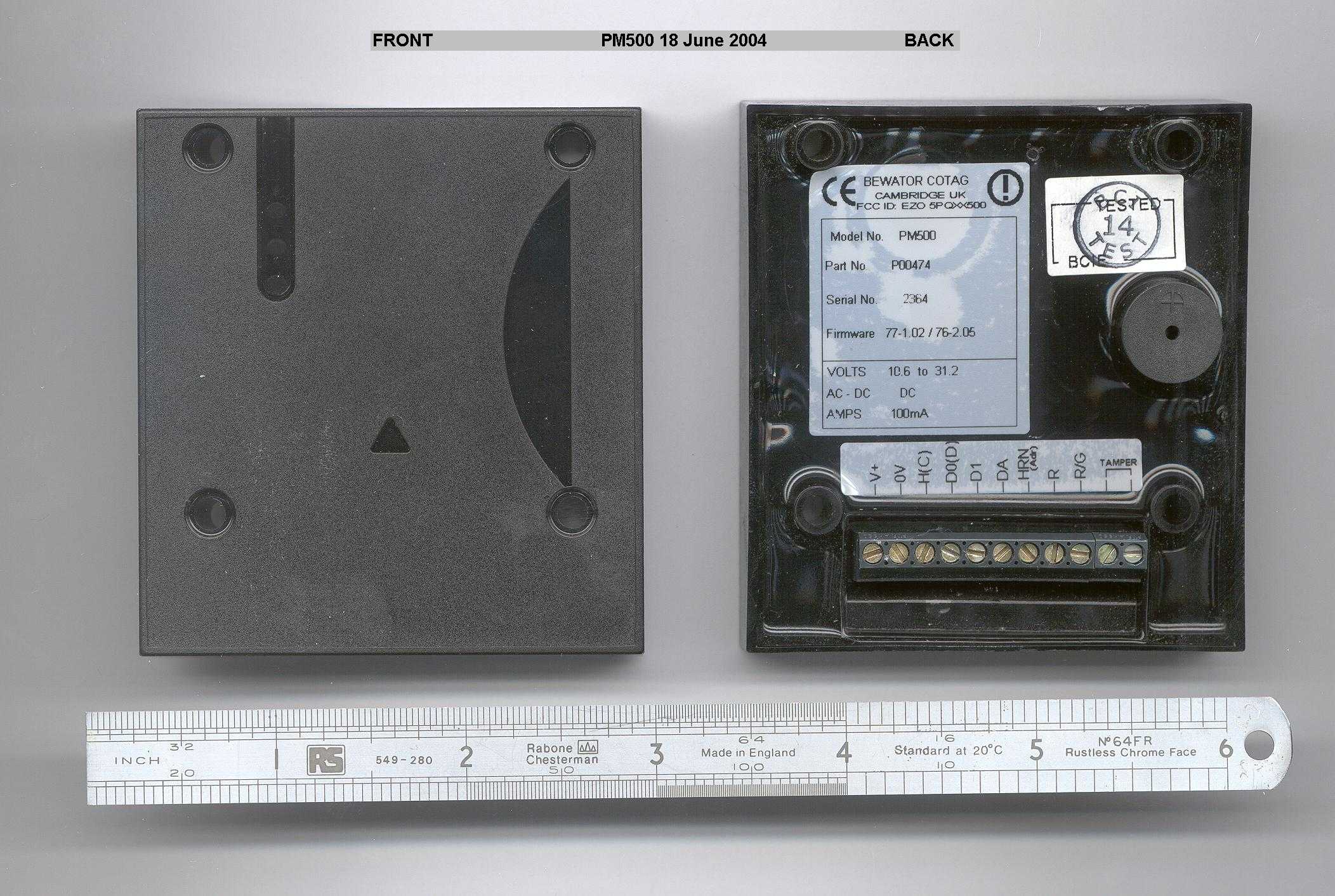
IN00127 - Issue 3 July 2003 - Page 1 of 2 Installation Note PM500-GP Panel Mount Reader IN00127 The PM500 Reader must be connected to a power supply and to a host access control system. Mounting and connecting 1. The PM500 Reader can be mounted within a sheet metal or plastic panel using four screws. If the panel is made of metal, the Reader must be mounted behind a 40mm square cut-out in the panel which must be positioned in the centre of the four mounting holes as shown in the diagram overleaf. When mounted in a metal panel, the Reader has a range of 5cm to 15cm (2in to 6in) dependent on the type of tag used, so it must be mounted in a position where the card or tag can easily be brought within this distance. 2. The connections required for the Reader are power supply connections (0V and +12V DC or +24V DC), data output connections for Wiegand or Magnetic Stripe (D0, D1, DA) or ASCII/TTL (H, D0, DA), and a connection from the host to the Data Hold input (H) if data lines from two Readers are to be connected in parallel. To promote EMC compliance we recommend you use 812 Cable as described here. If the Reader is mounted in a plastic panel then connect the screens at the host end only; at the PM500 the screens must be cut back and insulated. If the Reader is mounted in a metal panel then the overall screen must be connected at the host end and also to the metal panel. Do not connect any of the screens to the PM500 itself in either of these situations. Route the cables into the panel, then make the connections shown in the table below. Reader Function V+ Power supply +12V unregulated or 24V battery-backed* (absolute max 32V, min 10.6V, 100mA max) 0V Power supply 0V (-ve) (also ground reference for data output) H (C) “Data Hold” for Wiegand and Mag Stripe, “CTS” for ASCII/TTL D0 (D) “Data Zero” for Wiegand, “Data” for Mag Stripe, “TXD” for ASCII/TTL D1 “Data One” for Wiegand, “Strobe” for Mag Stripe DA “Data Available” for Wiegand, “Present” for Mag Stripe, “RTS” for ASCII/TTL HRN (Adr) Horn - 0V to sound, +5V to turn off R Red LED control - 0V for red LED R/G Single wire LED control - 0V for green LED, +5V for red LED TAMPER Tamper circuit connection (hard wired link)# IN00127 - Issue 3 July 2003 - Page 2 of 2 *The PM500 is designed to be operated by 12V unregulated power supplies, or 24V battery- backed power supplies. Operating voltage range is 10.6 to 32.0V. The upper voltage is intended to be compatible with the charging of 24V lead-acid batteries. Charge methods vary, and may be temperature dependent. 32V max is intended to be compatible with commonly used charging methods. If the upper operating voltage is exceeded then permanent damage may be caused. Installers and systems designers should check the max power supply voltage under all conditions. Do not operate the PM500 using unregulated 24V supplies. The PM500 current consumption can be significantly less than 100mA. The unloaded peak voltage from a nominal 24V unregulated supply will exceed the absolute max. #Two terminals are provided for use with a system 24hour tamper protection circuit. 3. Mount the Reader on the panel using four M3 nuts and bolts or self- tapping screws. If you wish you may fit the transparent window Part Number D01542 which gives a flush finish to the panel across the 40mm square cut-out. Fixing Dimensions (mm) The 40x40mm area within this dotted rectangle must be kept clear of all metal 73 5.5 19 48.5 9.7548.5 68 PM500 ReaderD01542 Window 4 2.5 39.8 39.8 4. Configure the Reader and test it (see the Proximity Readers Handbook HB00117). In order to reduce paper waste we do not ship a handbook with this product. You can download a copy of this or any other handbook from our website: http://www.bewator.co.uk FCC Statement This device complies with part 15 of the FCC Rules. Operation is subject to the following two conditions: 1) This device may not cause harmful interference, and 2) This device must accept any interference received, including interference that may cause undesired operation.
Block Diagram
J1-1J1-2 INPUT SUPPLYPROTECTION ®ULATION(U6, U10) VIN 10.5 - 35.0v RXCOIL PREAMP R34 (U2) (U3) 66KHz FILTER AGC (Q12, Q13) (U4) (U8) PEAKDETECTOR LEVELSHIFTER READERPIC (U9) GP0GP5 GP2 GP3 GP1 DIVIDEBY 2(½U7) !REQ / DATA !ACK /COMMAND RB0 RA4 HOSTPIC (U11) 7.392 MHz CRYSTAL RA0RA1RA2RA3 J1-3J1-7J1-8J1-9 HOLD (C) HORN (ADDR) R R / !G DIVIDEBY 14(U5,Q1) 3.696 MHz TXG C29 DIVIDEBY 2(½U7) 264 KHz (U1)DRIVER TXCOIL RB0RB6RB7 REDAMBERGREEN SOUNDER RB4 RB1RB2RB3 J1-4J1-5J1-6 (Q2,Q5)(Q6)(Q7) D0 (D)D1DA GATED132 KHz xx500 SERIES READER BLOCK DIAGRAM
Cover Letter(s)
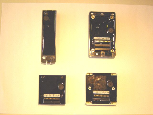
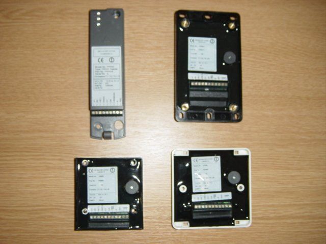
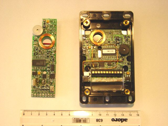
Bewator Ltd Mercers Row CAMBRIDGE CB5 8HY United Kingdom Federal Communications Commission To whom it may concern: Reference: xx500 Series of Proximity Readers Introduction The xx500 Series of Proximity Readers are designed to read the codes contained in Cotag™ coded cards and tags and to pass these codes, if valid, to a host system. These Readers are primarily for use by original equipment manufacturers (OEMs) to provide proximity reading for their own propietary access control systems. Each Reader requires a power supply, but can usually share the same supply as the door lock Reader Types The xx500 Series of Proximity Readers all use virtually identical electronics but encompass four different mounting styles. The PR500 Proximity Reader is a general purpose proximity reader which is small and slim and can be mounted on a wall or door frame. The HD500-2 Heavy Duty Proximity Reader has a stainless steel frame, held in place by four tamper- resistant screws, which cover the mounting screws. This makes it suitable for applications where vandalism could be a problem. The SP500 Switch Plate Proximity Reader fits a standard single surface mount or flush fitting back box, either metal or plastic, such as is used for light switches and mains plug sockets. 2 hole fixing for srewing to a standard single way back box. The PM500 Panel Mount Proximity Reader can be mounted within a sheet metal or plastic panel, such as is used on door entry intercom systems. 4 hole fixing for screwing to the back of the panel. Similarity to previous Readers The xx500 Series of Proximity Readers is the next generation of Cotag™ technology readers. Earlier generation included the 5291 as already authorised in EZO 5PQ 5291 Controllers and Tags / Cards As explained above, the Readers are primarily targetted to the OEM market, since users of Cotag™ controllers would for cost considerations use various Reading Heads and/or Loop Antennae. However all the Readers will work with 4000 / 5000 / P900 series controllers as authorised in EZO 5PQ 4000 / 4010 / 5000 / P900. All of the Cotag™ Readers, Reading Heads and Loop Antennae will operate with Cotag™ cards and tags as authorised in those series and/or in EZO 5PQ 1234.
Cover Letter(s)
payment of fees As there has been no reply to Graham Cox's email of 23 June, and the web site does not show that we have replied, I will post this copy of the email and Christer Liedholm's follow up of 29 June. Kevin O'Farrell 29 June 2004 -----Original Message----- From: Christer Liedholm [mailto:[email protected]] Sent: 29 June 2004 15:44 To: [email protected] Cc: Kevin O'Farrell; Graham Cox BWUK Subject: SV: Payment of FEES Hi Jaunice, have you been able to confirm our payment ($1040) regarding the application fee on 04/03/2004 according to the below? best regards /Christer Liedholm Bewator Från: Graham Cox [mailto:[email protected]] Skickat: den 23 juni 2004 16:12 Till: [email protected] Kopia: Kevin O'Farrell; Christer Liedholm Ämne: RE: Payment of FEES Hi Jaunice, I have faxed a reply with a copy of form 159 (page 1 only) completed for this application, to the OET at 301-326- 3290. I hope that the faxed form is legible; in case of difficulty I here attach a scan of the form. I did not send this through the approved route via your web site as the site does not provide a suitable classification for such attachments. Although the form 159 is not dated our bank seems to have cleared the payment on 3 April or maybe 4 March (I am note sure what date format they use). As you raised this request I assume there is some problem. Please could you let me know what is wrong with our payment? Regards Graham -----Original Message----- From: Philip Buckle Sent: 22 June 2004 19:59 To: Graham Cox; Kevin O'Farrell Subject: FW: Payment of FEES > ---------- > From: OET Generic account[SMTP:[email protected]] > Sent: Tuesday, June 22, 2004 7:49:54 PM > To: [email protected] > Subject: Payment of FEES > Auto forwarded by a Rule > To: Philip Buckle, Bewator Ltd From: Jaunice Green [email protected] FCC Application Processing Branch Re: FCC ID EZO5PQXX500 Applicant: Bewator Ltd. Correspondence Reference Number: 27037 731 Confirmation Number: EA178918 Have you paid the fees for this application? Can you provide a copy of the 159 form or other forms of payment. This information has to be current and show that you have paid the fees. The items indicated above must be submitted before processing can continue on the above referenced application. Failure to provide the requested information within 60 days of the original e-mail date may result in application dismissal pursuant to Section 2.917 (c) and forfeiture of the filing fee pursuant to section 1.1108. DO NOT reply to this e-mail by using the Reply button. In order for your response to be processed expeditiously, you must upload your response via the Internet at www.fcc.gov, Electronic Filing, OET Equipment Authorization Electronic Filing. If the response is submitted through Add Attachments, a message which informs the processing staff that a new exhibit has been submitted must also be submitted via Submit Correspondence. Also, please note that partial responses increase processing time and should not be submitted. Any questions about the content of this correspondence should be directed to the e-mail address listed below the name of the sender.
ID Label/Location Info
397839 Page 1 of 1 Items list (c) Bewator Cotag Title PR500-2 Reader Assy IL00507 Issue 2 Drawn MDS date 1-7-03 Authorised KOF date 9-7-03 Issued MDS date 14-7-03 Change notes CN001835 Actioned PMB date 18-12-03 Used on DL00505 Approvals Item Ident ML Description Qty UnitsPart No VarRemarks 1 2 Internal Frame (PR1-001) 1 D01406 3 Terminal Block 1 Y349 4 Contacts 1 D01409 5 6 Tx Coil 1 D01410 7 8 PR500-2 Reader PCA 1 P00504 9 10 PR500-2 Product Label 1 D01563 11 12 Potting Compound A/R V104 13 Potting Compound Activator A/R V104A 14 15 Configured label 1 D01541 1 2 3 Affix to potted side for AB configuration for GP configuration for JCI configuration 16 17 18 19 20 21 22 23 24 25 26 27 28 29 30 31 32 33 34
ID Label/Location Info
397840 Page 1 …
Text truncated - open the document above for the full version.
Contact Information
Applicant
Christer Liedholm(Vice President, Operations)
Technical Contact
Test Firm
DB TechnologyDave Smith
Technical Specifications
| # | Rule Parts | Frequency Range | Power Output |
|---|---|---|---|
| 1 | 15C | 0.131 MHz - 0.133 MHz | - |
Other Applications from Bewator Ltd.
EZO5PQ-SM500
Sep 26, 2000Contactless Smartcard Reader
Equipment Class
DSR - Part 15 Remote Control/Security Device TransceiverEZO5PQ5290
Jan 27, 1998Tag Reader Transmitter
Equipment Class
DCD - Part 15 Low Power Transmitter Below 1705 kHzEZO5PQ4010
Nov 27, 1997Store Security Device
Equipment Class
DCD - Part 15 Low Power Transmitter Below 1705 kHzEZO5PQ4000
Jul 27, 1993DCD - Part 15 Low Power Transmitter Below 1705 kHz
Equipment Class
DCD - Part 15 Low Power Transmitter Below 1705 kHz