FA77EWDXSERIESPassive Infrared and Microwave Combination Detecto
Optex Incorporated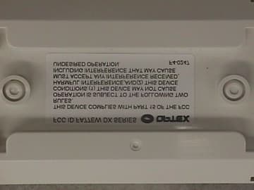
Click to zoom
Application Details
- Equipment Class
- FDS - Part 15 Field Disturbance Sensor
- Date of Grant
- May 23, 2000
- Application Purpose
- Original Equipment
- Date of Application
- Apr 23, 2000
- Equipment Note
- Passive Infrared and Microwave Combination Detecto
- Frequency Range
- 10525.00000000 - 10525.00000000
- Company
- Optex Incorporated
- Country
- United States
Documents & Files
Document Text
Text extracted from the exhibit documents filed with the FCC. Open a document above to read the original.
Test Report
EXHIBIT 4 REPORT OF MEASUREMENTS 2.1033 (b)(6) REPORT OF MEASUREMENTS GENERAL Applicant:OPTEX CO., LTD Device:10.525 GHz Field Disturbance Sensor Model:DX-60/DX-60 Plus Serial Number:N/A FCC ID:FA77EWDXSERIES Input Power Requirements: 9 to 18 VDC, 40 mA (12 VDC Nominal) Rule Section:Part 15, Subpart C, Section 15.245 TEST METHODS PERFORMED 15.245 (b)Radiated Emissions, Fundamental 15.245 (b)(1) Radiated Emissions, Harmonics 15.245 (b)(3) Radiated Emissions, Band Edges 15.245 (b)(3) Radiated Emissions, Spurious Emissions, 30 MHz to 52.625 GHz TEST RESULTS 15.245 (a)The device is an intentional radiator used as a field disturbance sensor. 15.245 (b)The device operates within the 10.500 to 10.550 GHz frequency band. The field strength of the fundamental emission did not exceed 2500 millivolts per meter, average. 15.245 (b)(1)The device does not produce harmonic emissions below 17.7 GHz. 15.245 (b)(1)(i)The device is intended to be used only within buildings and the field strength of harmonic emissions did not exceed 25.0 millivolts per meter. TEST RESULTS (continued) 15.245 (b)(2)All radiated emissions measurements were extrapolated to the specified 3 meter test distance. 15.245 (b)(3)The emissions radiated outside of the specified frequency band of 10.500 to 10.550 GHz did not exceed the general radiated emission limits of 15.209. 15.245 (b)(4)The requirements of 15.35 for averaging pulsed emissions and limiting peak emissions were met. NOTES 15.31 (a)(b)All measurements were made in accordance with ANSI C63.4:1992. 15.31 (c)The device does not use swept frequency techniques. 15.31 (d)All testing was performed on Retlif Testing Laboratories Ronkonkoma, NY test site which has been listed with the FCC. 15.31 (e) Variation of the radiated signal level of the fundamental frequency component was performed with the supply voltage varied between 85 and 115% of nominal (12 VDC). This was also performed at 85% of the minimum and 115% of the maximum rated input voltage range. 15.31 (f)(1)Where testing was performed at distances other than the specified test distance, the obtained readings were extrapolated to the specified test distance using an inverse linear-distance extrapolation factor (20 dB / decade) for measurements between 30 MHz and 40 GHz. For measurements at frequencies above 40 GHz, an inverse linear- distance squared factor ( 40 dB / decade) was utilized. 15.31 (f)(5)The device was rotated 360° in order to maximize the radiated emissions. The maximum field strength observed has been reported. 15.31 (g)All consumer accessible controls were adjusted in order to maximize emissions (MW Range Control). A one meter length of unshielded twisted pair wire was connected to each of the relay and tamper outputs. 15.31 (m)The device operates at a single frequency of 10.525 GHz. 15.31 (o)All emissions within 20 dB of the specified limits have been reported unless otherwise stated. 15.33 (a)(2)The device operates above 10 and below 30 GHz at a frequency of 10.525 GHz. Therefore radiated emissions measurements were made from 30 MHZ to 52.625 GHz, the fifth harmonic. DUTY CYCLE Forty microsecond (40 μSec) pulses are applied to SD1 at a repetition rate of 1kHz. This yields a duty cycle of 4%, 40 μSec divided by 1 mSec. This duty cycle was applied to the obtained peak readings in order to determine the average value of the emissions. TEST DISTANCES In order to obtain adequate system sensitivity at the harmonic frequencies of interest, it was necessary to perform certain measurements at a distance less than 3 meters. Care was taken to ensure that all measurements were taken in the far field region. The antenna was determined to be in the far field IFF: d ≥ 2 D 2 ⁄ λ Where: d = Test Distance D = Largest Antenna Length λ = Wavelength at the Frequency of Interest Solving for d yields the minimum test distances shown in the table below. Also shown is the actual test distance utilized. Frequency GHzMinimum Test Distance MetersActual Test Distance Meters 10.5252.73 21.0501.52 31.5751.01 42.1000.51 52.6250.71 SPECTRUM ANALYZER DESENSITIZATION CONSIDERATIONS Due to the nature of the emissions being measured, care was taken to ensure that the resolution bandwidth of the spectrum analyzer was adequate to provide accurate peak field strength measurements. The following formula was utilized: Pulse Desensitization (δ) = 20 log (Pulsewidth * bandwidth * 1.5) Setting the above equal to zero and utilizing the 40 microsecond pulse width yields a minimum required bandwidth of 33.3 kHz. The 1 MHz bandwidth specified in ANSI C63.4 was utilized for all fundamental and harmonic measurements. TEST DATA RADIATED EMISSIONS, FUNDAMENTAL 15.245 (b) TEST SAMPLE: 10.525 GHz Field Disturbance Sensor FCC ID: FA77EWDXSERIESAPPLICANT: OPTEX CO., LTD TEST METHOD: Radiated Emissions, Fundamental SPECIFICATION: FCC Part 15, Section 15.245 (b) PERFORMED BY: P. Lananna DATE: 3/7/00 Field Strength of Fundamental Frequency GHz Antenna Position H / V EUT O rie nta tio n X / Y/ Z Meter Reading dBuV Antenna Factor +dB Corrected Reading dBuV/m C onverted Reading mV/m Limit at 3 Meters mV/m 10.525HX76.930106.9221.32,500 VX6433094.351.92,500 HY65.03095.056.22,500 VY75.630105.6190.52,500 HZ58.23088.225.72,500 VZ69.13099.190.22,500 Detector Function: Peak Test Distance: 3 Meters Resolution Bandwidth: 1 MHz Video Bandwidth: 3 MHz TEST SAMPLE: 10.525 GHz Field Disturbance Sensor FCC ID: FA77EWDXSERIESAPPLICANT: OPTEX CO., LTD TEST METHOD: Radiated Emissions, Fundamental, Input Voltage Variation SPECIFICATION: FCC Part 15, Section 15.245 (b), 15.31(e) PERFORMED BY: P. Lananna DATE: 3/7/00 Input Voltage Variation Frequency GHz Test Voltage % N o mina l Test Voltage VDC Meter Reading dBuV Antenna Factor +dB Corrected Reading dBuV/m C onverted Reading mV/m Limit at 3 Meters mV/m 10.52585% (Vmin) 7.6574.830104.8173.82,500 100% (Vnom) 12.074.830104.8173.82,500 115% (Vmax) 20.774.830104.8173.82,500 Detector Function: Peak Test Distance: 3 Meters Resolution Band…
Text truncated - open the document above for the full version.
Contact Information
Applicant
Hideo Kitaoka(President)
Technical Contact
Retlif Testing LaboratoriesThomas J Schneider
[email protected]631-737-1500
795 Marconi Avenue · Ronkonkoma, New York · United States
Non-Technical Contact
Retlif Testing LaboratoriesMichelle Tirado
[email protected]631-737-1500
Technical Specifications
| # | Rule Parts | Frequency Range | Power Output |
|---|---|---|---|
| 1 | 15C | 10.53 GHz - 10.53 GHz | - |
Other Applications from Optex Incorporated
FA7MX-SERIES
Apr 15, 2001Indoor Field Disturbance Sensor
Equipment Class
DSR - Part 15 Remote Control/Security Device Transceiver
FA77EW
Jun 25, 1998FDS - Part 15 Field Disturbance Sensor
Equipment Class
FDS - Part 15 Field Disturbance SensorFA77EWRC-2
Nov 23, 1992Wireless Security System Receiver
Equipment Class
CRR - Superregenerative ReceiverFA77EWRS-2
Nov 23, 1992Wireless Security System Receiver
Equipment Class
CRR - Superregenerative ReceiverFA77EWTI-2
Nov 23, 1992Wireless Motion Sensor Transmitter
Equipment Class
DSC - Part 15 Security/Remote Control Transmitter