FA7MX-SERIESIndoor Field Disturbance Sensor
Optex Incorporated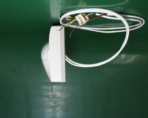
Click to zoom
Application Details
- Equipment Class
- DSR - Part 15 Remote Control/Security Device Transceiver
- Date of Grant
- Apr 15, 2001
- Application Purpose
- Original Equipment
- Date of Application
- Apr 15, 2001
- Equipment Note
- Indoor Field Disturbance Sensor
- Frequency Range
- 2446.00000000 - 2454.00000000
- Company
- Optex Incorporated
- Country
- United States
Documents & Files
Document Text
Text extracted from the exhibit documents filed with the FCC. Open a document above to read the original.
Cover Letter(s)
American Telecommunications Certification Body Inc. 6731 Whittier Ave, McLean, VA 22101 March 27, 2001 RE: FCC ID FA7MX-SERIES Dear Motomu, I have a couple of items that must be cleared up on the documentation for this field disturbance sensor before I can proceed. 1.) Internal Photographs: It is an FCC requirement that all RF shielding be removed for photographs. Please resubmit. In addition, I find the photos a bit small. Please submit just one photo per page and as large as practical. 2.) Please provide test setup photos as an extraction from the test report. Do not submit the test report twice. 3.) The Block Diagram is not of sufficient detail to qualify for Confidentiality. Please submit new block diagram, or de-list the existing block diagram by submitting a new confidentiality request. 4.) The operational description is a bit weak. Please provide more detail as to how the circuitry performs it’s functions. If this is to be Confidential, it can be requested. All other items on the Application appear to be in order. Please resubmit the requested documents through the AmericanTCB website. William H. Graff Examining Engineer President and Director of Engineering The items indicated above must be submitted before processing can continue on the above referenced application. Failure to provide the requested information within 30 days of the original e-mail date may result in application dismissal pursuant to Section 2.917(c). Correspondence should be considered part of the permanent submission and may be viewed from the Internet after a Grant of Equipment Authorization is issued. Please do not reply to this correspondence using the email reply button. In order for your response to be processed expeditiously, you must attach your answers to email correspondence. Reply to the examiner at the email address shown below. Also, please note that partial responses increase processing time and should not be submitted. Any questions about the content of this correspondence should be directed to the e-mail address listed below the name of the sender.
Cover Letter(s)
American Telecommunications Certification Body Inc. 6731 Whittier Ave, McLean, VA 22101 March 30, 2001 RE: FCC ID: FA7MX-SERIES My final review produced one nagging doubt about this application. 1.) 15.245 (b)(1)(i) specifies that field disturbance sensors used exclusively within a building or to open building doors are limited to a maximum field strength of 25mV/meter (68 dBuV/m). The Users Manual specifically warns against outdoor installation. Please justify William H. Graff Examining Engineer President and Director of Engineering mailto:[email protected] The items indicated above must be submitted before processing can continue on the above referenced application. Failure to provide the requested information may result in application termination. Correspondence should be considered part of the permanent submission and may be viewed from the Internet after a Grant of Equipment Authorization is issued. Please do not respond to this correspondence using the email reply button. In order for your response to be processed expeditiously, you must submit your documents through the AmericanTCB.com website. Also, please note that partial responses increase processing time and should not be submitted. Any questions about the content of this correspondence should be directed to the sender.
External Photos
EXTERNAL PHOTO MX-40:FA7MX-SERIES Front View Back View Right Side View Left Side View Top View Bottom View
ID Label/Location Info
Label Position of MX-40 (FCC ID: FA7MA-SERIES) Label will be affixed at No.6 described in the following page. CONSTRUCTION DIAGRAM MX-40 TYPEGENERIC NAMEMANUFACTURER 1 BASE 1 TERURAN GP35 TOYORACK 700 ABS 94HB 2COVER1ABS94HB 3LENS1 HJ 580 SHOLEX F 6080V HIZEX 1300J POLYETHYLENE MITSUBISHI CHEMICAL CORPORATION POLYMER PRODUCTS CO SHOWA DENKO KK MITSUI PETROCHEMIAL INDUSTRIES LTD 4SPONGE PAD 11POLYETHYLENE SPONGE 5RUBBER CAP1CHLOROPRENE RUBBER 6RATING LABEL1PGDQ2,PGGU2 OR PGJI2 7MIRROR1ALUMINUM 8LED LENS1PMMA CHI MEI CORPORATION ASAHI CHEMICAL INDUSTRY CO.,LTD 9SPONGE PAD 21NEOPRENE SPONGE 10LOT NO. LABEL1ART PAPER 11TERMINAL LABEL1YUPO UL FLAME CLASS UL (FILING NO.) PARTS LIST : MX-40 MATERIAL PARTS NAMEQTY. PARTS NO.
ID Label/Location Info
Label Position of MX-40 (FCC ID: FA7MA-SERIES) Label will be affixed at No.6 described in the following page. CONSTRUCTION DIAGRAM MX-40 TYPEGENERIC NAMEMANUFACTURER 1 BASE 1 TERURAN GP35 TOYORACK 700 ABS 94HB 2COVER1ABS94HB 3LENS1 HJ 580 SHOLEX F 6080V HIZEX 1300J POLYETHYLENE MITSUBISHI CHEMICAL CORPORATION POLYMER PRODUCTS CO SHOWA DENKO KK MITSUI PETROCHEMIAL INDUSTRIES LTD 4SPONGE PAD 11POLYETHYLENE SPONGE 5RUBBER CAP1CHLOROPRENE RUBBER 6RATING LABEL1PGDQ2,PGGU2 OR PGJI2 7MIRROR1ALUMINUM 8LED LENS1PMMA CHI MEI CORPORATION ASAHI CHEMICAL INDUSTRY CO.,LTD 9SPONGE PAD 21NEOPRENE SPONGE 10LOT NO. LABEL1ART PAPER 11TERMINAL LABEL1YUPO UL FLAME CLASS UL (FILING NO.) PARTS LIST : MX-40 MATERIAL PARTS NAMEQTY. PARTS NO.
Internal Photos
INTERNALPHOTO Circuit Board: Front Circuit Board: Back
Operational Description
MX-40 Technical description MX40 has a microwave Doppler (MW) detector and a Passive infrared (PIR) detector. When both detectors detect a human at the same time, MX-40 outputs an alarm output from terminal. And LED indicates alarm conditions. MW detector transmits and receives S-band microwave (2.45 GHz). If there is a moving human in the detection area, it causes changes in received microwave frequency (Doppler effect). MW detector outputs signals when there are such changes. PIR detector detects temperature contrasts between human body and back ground in the detection area. Block diagram description MW SENSOR MW SENSOR transmits and receives S-band microwave (2.45 GHz). If there is a moving object in the detection area, it causes changes in received microwave frequency (Doppler effect). MIXER outputs signals when there are such changes. Fundamental microwave frequency is generated by OSC, and Microwave is emitted from the antenna (Inverted L type antenna /4) through MIXER. The reflections of Microwave at objects in the detection area are received at the antenna, and mixed at MIXER with fundamental microwave frequency. If there is human moving in the detection area, the microwave frequency is added with moving speed of the human for Doppler effect. Then MIXER outputs the Doppler signals (110HZ) to AMPLIFIER. AMPLIFIER Signals from MW SENSOR are amplified at AMPLIFIER (90dB). COMPERRATOR Amplified signals are compared with the threshold level at COMPERATOR. If the signal exceeds the threshold level, the detection signal shall be output to TIMER. TIMER The detection signal is hold for the predetermined period at TIMER. The switch connected with TIMER in CUSTOM IC is activated by the detection signal from TIMER. PIR signals are accepted during this period. PIR SENSOR Infrared radiations from human body are focused with optics and received with pyro- element. Pyro-element converts infrared radiations to electrical signals. AMPLIFIER Signals from PIR SENSOR are amplified at AMPLIFIER. COMPERATOR Amplified signals are compared with the threshold level at COMPERATOR. If the signal exceeds the threshold level, the detection signal shall be output to PULSE COUNT. PULSE COUNT During the switch between COMPERATOR and PULSE COUNT is ON, PULSE COUNT counts the signals from COMPERATOR. If PULSE COUNT counts over the predetermined counter in the predetermined period, the detection signal shall be output to OUTPUT TIMER. The predetermined counter can be selectable 2 or 4 with PULSE COUNT SWITH. OUTPUT TIMER The detection signal is hold for the predetermined period at OUTPUT TIMER. RELAY DRIVE and LED DRIVE activated during this period. RELAY DRIVE, LED DRIVE The alarm output relay and the LED for alarm indication shall be activated during the period of OUTPUT TIMER activation.
Test Report
Test report No.: 21CE0001-YW-1 Page: 2 of 13 Issued date:February28,2001 FCC ID: FA7MX-SERIES A-pex International Co., Ltd. YOKOWA LAB. 108 Yokowa-cho, Ise-shi, Mie-ken 516-1106 JAPAN Telephone:int +81 596 39 1485 Facsimile: int +81 596 39 0232 CONTENTS PAGE SECTION 1: Client information 3 SECTION 2: Equipment under test (E.U.T.)3 SECTION 3: Test specification, methods & procedures4 SECTION 4: Operation of E.U.T. during testing5 SECTION 5: Summary of test results 7 SECTION 6: Test instruments10 SECTION 7: Radiated emission11 APPENDIX 1: Photographs of test setup12 APPENDIX 2: Data of EMI test13 Test report No.: 21CE0001-YW-1 Page: 3 of 13 Issued date:February28,2001 FCC ID: FA7MX-SERIES A-pex International Co., Ltd. YOKOWA LAB. 108 Yokowa-cho, Ise-shi, Mie-ken 516-1106 JAPAN Telephone:int +81 596 39 1485 Facsimile: int +81 596 39 0232 SECTION 1: Client information OPTEX CO., LTD. 4-7-5 Nionohama Otsu Shiga Japan Contact person, Norikazu Murata Telephone No.+077-524-6990 Fax No.+077-524-9399 SECTION 2: Equipment under test (E.U.T.) 2.1Identification of E.U.T. Unique Type Identification: Security Sensor Model No.: MX-40PI Serial No.: 3 Rating: DC 12V Country of Manufacture: Japan Receipt Date of Sample: February 7 , 2001 2.2Product Description Model:MX-40PI (referred to as the EUT in this report) is security sensor. The specification is as follows; The OPTEX MX-40PI is a range of passive infrared and microwave detectors designed to detect movement of an intruder and activate an alarm control. Transmission frequency:2450MHz Modulation:None Antenna type:Inverted L-type antenna(Integral) Test report No.: 21CE0001-YW-1 Page: 4 of 13 Issued date:February28,2001 FCC ID: FA7MX-SERIES A-pex International Co., Ltd. YOKOWA LAB. 108 Yokowa-cho, Ise-shi, Mie-ken 516-1106 JAPAN Telephone:int +81 596 39 1485 Facsimile: int +81 596 39 0232 SECTION 3: Test specification, methods & procedures 3. 1Test Specification Test Specification: FCC Part 15 Subpart C Title: FCC 47CFR Part15 Radio Frequency Device Subpart C Intentional Radiators 15.245 Operation within the Band 2435 – 2465MHz 3.2Methods & Procedures No.ItemTest ProcedureSpecificationRemarks 1 Electric Field Strength of Fundamental Emission FCC/ANSI C63.4:1992 15.245 - 2 Electric Field Strength of Spurious Emission FCC/ANSI C63.4:1992 15.245 / 15.209 - Test report No.: 21CE0001-YW-1 Page: 5 of 13 Issued date:February28, 2001 FCC ID: FA7MX-SERIES A-pex International Co., Ltd. YOKOWA LAB. 108 Yokowa-cho, Ise-shi, Mie-ken 516-1106 JAPAN Telephone:int +81 596 39 1485 Facsimile: int +81 596 39 0232 SECTION 4: Operation of E.U.T. during testing 4.1Operating Modes The EUT exercise program used during radiated testing was designed to exercise the various system components in a manner similar to typical use. The sequence is used Transmitting Justification: The system was configured in typical fashion (as a customer would normally use it) for testing. 4.2 Configuration and peripherals Front View Top View B AC 100V/60Hz AC 100V/60Hz A : EUT A : EUT B Test report No.: 21CE0001-YW-1 Page: 6 of 13 Issued date:February28, 2001 FCC ID: FA7MX-SERIES A-pex International Co., Ltd. YOKOWA LAB. 108 Yokowa-cho, Ise-shi, Mie-ken 516-1106 JAPAN Telephone:int +81 596 39 1485 Facsimile: int +81 596 39 0232 Description of EUT and Support equipment No.ItemModel numberSerial numberManufacturerRemark ASecurity SensorMX-40PI3OPTEXEUT BDC Power Supply--A-Pex- List of cables used No.Name Length (m) ShieldBackshell Material DC Cable(Alarm) 1.5 N - Signal Cable 0.9 N - AC Cable 2.0 N- Test report No.: 21CE0001-YW-1 Page: 7 of 13 Issued date:February28, 2001 FCC ID: FA7MX-SERIES A-pex International Co., Ltd. YOKOWA LAB. 108 Yokowa-cho, Ise-shi, Mie-ken 516-1106 JAPAN Telephone:int +81 596 39 1485 Facsimile: int +81 596 39 0232 SECTION 5: Summary of test results 5.1Test results No.ItemTest ProcedureSpecificationRemarksResult 1 Electric Field Strength of Fundamental Emission FCC/ANSI C63.4:1992 FCC Part15 Subpart C 15.245 Test distance : 3mComplies 2 Electric Field Strength of Spurious Emission FCC/ANSI C63.4:1992 FCC Part15 Subpart C 15.245 / 15.209 Test distance : 3mComplies A-PEX INTERNATIONAL hereby confirms that E.U.T., in the configuration tested, complies with the specifications FCC Part15 Subpart C. 5.1.1 Electric Field Strength Measurement of Fundamental Frequency The initial step in collecting radiated data was a spectrum analyzer peak scan of the measurement range The final data was reported in the worst-case emissions. The follwing table lists frequency at which emissions were measured using a Peak detector. The minimum margin to the limit is as follows :(A2-1 : DC12V) Ant.S/A CorrectionField FrequencyPol.ReadingFactorStrength LimitMargin (MHz)(dB V) (dB)(dB V/m) (dB V/m)(dB) 2449.62Hor92.31.093.3113.920.6 Field strength calculation The field strength is calculated by adding the Antenna Factor, Cable Factor and subtracting the Amplifier Gain from the measured reading. The sample calculation is as follows : FS = RA + AF + CF + AT - AG where FS = Field Strength RA = Receiver Amplitude AF = Antenna Factor CF = Cable Factor AG = Amplifier Gain Assume a Spectrum Analyzer reading of 92.3 dB V is obtained. The antenna Factor of 28.8 dB, and Cable Factor of 6.7 dB is added. The Amplifier Gain of 34.5 dB is subtracted, giving a field strength of 93.3 dB V/m. FS = 92.3 + 28.8 + 6.7 – 34.5 = 93.3dB V/m Test report No.: 21CE0001-YW-1 Page: 8 of 13 Issued date:February28, 2001 FCC ID: FA7MX-SERIES A-pex International Co., Ltd. YOKOWA LAB. 108 Yokowa-cho, Ise-shi, Mie-ken 516-1106 JAPAN Telephone:int +81 596 39 1485 Facsimile: int +81 596 39 0232 5.1.2 Electric Field Strength of Spurious Emission The initial step in collecting radiated data was a spectrum analyzer peak scan of the measurement range The final data was reported in the worst-case emissions. Detector: 30MHz to 1GHzQuasi peak : 1GHz to 26GHzPeak and Average The minimum margin to the limit is as follows (A2-4) Ant.S/A(AV) Correcti…
Text truncated - open the document above for the full version.
Test Setup Photos
Test report No.: 21CE0001-YW-1 Page: 12 of 13 Issued date:February28, 2001 FCC ID: FA7MX-SERIES A-pex International Co., Ltd. YOKOWA LAB. 108 Yokowa-cho, Ise-shi, Mie-ken 516-1106 JAPAN Telephone:int +81 596 39 1485 Facsimile: int +81 596 39 0232 APPENDIX 1: Photographs of test setup(Radiated emission)
Contact Information
Applicant
Hideo Kitaoka(President)
Technical Contact
A-Pex International Co., LtdNaoki Sakamoto
[email protected]+81 596 39 1485
108 Yokowa-cho · Ise-shi, Mie-ken · Japan
Non-Technical Contact
A-Pex International Co., Ltd.Motomu Kawano
[email protected]+81 596 24 8116
Test Firm
UL Japan, Inc.Kazunori Nishimura
Technical Specifications
| # | Rule Parts | Frequency Range | Power Output | Emission |
|---|---|---|---|---|
| 1 | 15C | 2.45 GHz - 2.45 GHz | 2.00 mW | N0N |
Other Applications from Optex Incorporated
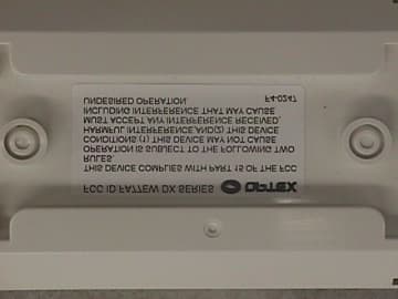
FA77EWDXSERIES
May 23, 2000Passive Infrared and Microwave Combination Detecto
Equipment Class
FDS - Part 15 Field Disturbance Sensor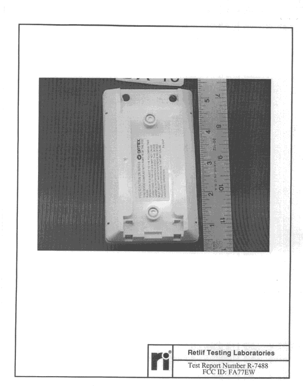
FA77EW
Jun 25, 1998FDS - Part 15 Field Disturbance Sensor
Equipment Class
FDS - Part 15 Field Disturbance SensorFA77EWRC-2
Nov 23, 1992Wireless Security System Receiver
Equipment Class
CRR - Superregenerative ReceiverFA77EWRS-2
Nov 23, 1992Wireless Security System Receiver
Equipment Class
CRR - Superregenerative ReceiverFA77EWTI-2
Nov 23, 1992Wireless Motion Sensor Transmitter
Equipment Class
DSC - Part 15 Security/Remote Control Transmitter