FBIHANDHELDMICHANDHELD WIRELESS MICROPHONE
ClearOne, Inc.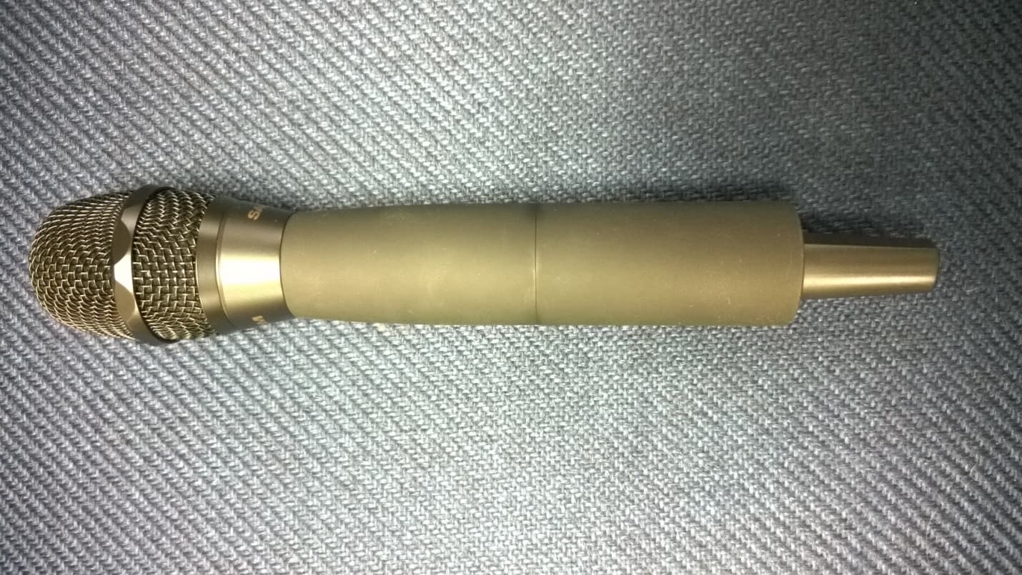
Click to zoom
Application Details
- Equipment Class
- TBF - Licensed Broadcast Transmitter Held to Face
- Date of Grant
- Dec 29, 2014
- Application Purpose
- Original Equipment
- Date of Application
- Dec 29, 2014
- Equipment Note
- HANDHELD WIRELESS MICROPHONE
- Frequency Range
- 614.00000000 - 618.00000000
- Company
- ClearOne, Inc.
- Country
- United States
Documents & Files
Document Text
Text extracted from the exhibit documents filed with the FCC. Open a document above to read the original.
Users Manual
Digital Wireless Microphone Systems Quick Start Guide Setting Up Pre-Engineered ClearOne ® Systems for Optimal Performance Master Slave Terminators Headquarters: salt Lake City, ut usa 5225 Wiley Post Way suite 500 salt Lake City, ut 84116 tel: 801.975.7200 toll Free: 800.945.7730 Fax: 801.977.0087 e-mail: [email protected] eMea tel: 44 (0) 1189.036.053 e-mail: [email protected] aPaC tel: 852.3590.4526 e-mail: [email protected] L ataM tel: 801.974.3621 e-mail: [email protected] techsales tel: 800.707.6694 e-mail: [email protected] technical support tel: 800.283.5936 e-mail: [email protected] CLearOne LOCatIOns Open the Cartons: Confirm everything on the packing slip is enclosed. Set up the Docking Station: 1. ClearOne transmitters are shipped with rechargeable batteries. Plug in the charging dock, put the batteries in the transmitters, then place the transmitters in the dock while you set up the rest of the system. Mount the Receivers in the Rack 2. and connect them to power. Confirm the displays light up. Pre-engineered Antenna Design: 3. If you provided ClearOne with a floor plan, you will find a marked up version in the box (or, in your Email in-box) showing the antenna design along with the antennas and pre-made cables. Place the antennas according to the drawings. Your Own Design: A. If you did not request an antenna design, place the antennas according to the enclosed Antenna Applications Guide Improper antenna placement is the main cause of poor RF performance. Dipole Antennas: B. Dipole antennas mounted to the rack equipment can easily be locked away in a closet/rack cabinet. This results in poor RF performance because there is no line of sight between the transmitter and receiver antenna. Therefore, remote antennas are preferred. See the Antenna Application Guide for details. Connect the Antennas:4. The receiver that connects to the antennas should be set as the Antenna Master receiver. Master is the factory default. If your system daisy-chains antennas together, the downstream receivers should be set as Slaves. Terminators are used on the last system in the daisy-chain. Use ClearOne Remote’s Antenna Setup Wizard, which opens automatically the first time you connect. You can also find the wizard under the SETTINGS tab of the main page. If connecting ClearOne active remote antennas, make sure the red LED lights up. If not, check the receiver’s antenna phantom power setting using the ClearOne Remote Control Software. Connect the analog outputs to the mixer:5. The system is shipped with Euro block connectors. The default output level is set to +4 dBu. Note that factory default for the front panel headphone jack is set for mixed line-level out. Use ClearOne Remote>Settings>Headphone, to reset for headphones. CAUTION! Turn off phantom power from the mixer. Phantom power distorts the audio quality of your microphones. System Test:6. In most cases, the system is now ready to use. Confirm all channels pass audio perfectly. Modifications (FCC 15.21) Changes or modifications to this equipment not expressly approved by ClearOne may void the user’s authority to operate this equipment. This device complies with Industry Canada licence-exempt RSS standard(s). Operation is subject to the following two conditions: (1) this device may not cause interference, and (2) this device must accept any interference, including interference that may cause undesired operation of the device. Applies to WS80-T: Under Industry Canada regulations, this radio transmitter may only operate using an antenna of a type and maximum (or lesser) gain approved for the transmitter by Industry Canada. To reduce potential radio interference to other users, the antenna type and its gain should be so chosen that the equivalent isotropically radiated power (e.i.r.p.) is not more than that necessary for successful communication. This radio transmitter (WS80-T) has been approved by Industry Canada to operate with the antenna types listed below with the maximum permissible gain and required antenna impedance for each antenna type indicated. Antenna types not included in this list, having a gain greater than the maximum gain indicated for that type, are strictly prohibited for use with this device. Monopole antenna, 0dbi gain, 50 ohm impedance. Le présent émetteur radio (DS80-T) a été approuvé par Industrie Canada pour fonctionner avec les types d’antenne énumérés ci-dessous et ayant un gain admissible maximal et l’impédance requise pour chaque type d’antenne. Les types d’antenne non inclus dans cette liste, ou dont le gain est supérieur au gain maximal indiqué, sont strictement interdits pour l’exploitation de l’émetteur. For Full Control Select the new parameter values and click OK to save changes to the receiver. Editing Transmitter Parameters: The easiest and most intuitive way to set the parameters of ClearOne transmitters and receivers is with ClearOne Remote software. Load ClearOne Remote from the disk provided onto a computer running Windows XP or Windows 7 (32 or 64-bit) and connect to the receiver via USB or RS232. Then open ClearOne Remote and select ONLINE. Open The Channel Edit Window: 1) The [Click to Edit] function opens the edit window of the channel you wish to edit. 2) Select the functions you want to edit and enter the parameter. (The various functions are described below.) Click [OK] to save the changes and close the Channel Edit window. 3) You will notice that the [Needs to Sync] alert is lit. This indicates that one or more parameters are in queue in the receiver ready to be downloaded and implemented with the next transmitter Sync of the channel. 1) 2) Digital Wireless Microphone Systems Using the ClearOne remote software: Click to Edit the channel’s parameters 3) The “Need To Sync” alert is lit. Sync the transmitter to apply the selected parameters. ClearOne Remote provides the following functions: File:1. Save a PDF image of the screen. Settings:2. Phantom Power:A. Turn antenna phantom …
Text truncated - open the document above for the full version.
External Photos
APPLICANT: CLEARONE INC. FCC ID: FBIHANDHELDMIC IC: 1970A-HANDHELDMIC FRONT VIEW REAR VIEW BOTTOM VIEW TOP VIEW
ID Label/Location Info
5225 Wiley Post Way, Suite 500 Salt Lake City, UT 84116 Phone: 801-975-7200 Fax: 801-303-5711 This document contains confidential information proprietary to ClearOne and may not be copied in whole or in part by any means without the prior authorization of ClearOne. SCALE N.T.S.DO NOT SCALESHEET 1 OF 1 REV SIZEPART # DESCRIPTION A ANGLES: 1 2 PLACE DIMS: 0.02 3 PLACE DIMS: 0.005 TOLERANCES DRAWN BY PLOT DATE DATE UNLESS OTHERWISE SPECIFIED ALL DIMENSIONS ARE IN INCHES NOTES: UNLESS OTHERWISE SPECIFIED 1. MATERIAL 9.4MIL, 40# LINER, 50# FACE PREMIUM COATED, SMOOTH THERMAL TRANSFER PAPER LABEL STOCK WITH GENERAL PURPOSE, ALL TEMPERATURE PERMANENT ACRYLIC ADHESIVE COLOR: WHITE MANUF REF: ZEBRA #Z 93675P (Z ULTIMATE 3000T) 2. PRINTING PDF DOCUMENT IS FOR REFERENCE ONLY PRINT COLOR: 5095 RESIN REVISION SPECIFICATION REV: NAME: DATE: DCN: 1.0 JPHELPS 14 NOV 2014 000536 INITIAL RELEASE JPHELPS LBL-0395-002 LABEL UNIT ASSY PROD ID WIRELESS HANDHELD CARDIOID TRANSMITTER (RF M500) COMPRESSED 1.0 04 NOV 2014 04 NOV 2014 CONTRACT MANUFACTURER ASCALADE EGI ICT INOVAR WELLEX CODE 02 05 03 01 04 FACTORY CODE TABLE FLEXTRONICS - U.S.A. 06 FLEXTRONICS - DG CHINA 07 FLEXTRONICS - FY CHINA 08 PTS 09 OPCOM 11 UNIKA 10 ARROW OEM 12 ACT 13 AV LEADER 14 COMFORTCOMMS 15 MINNRAY 16 EDCO 17 MSI 18 SUPERMICRO 19 EPIPHAN 20 CLEARONE C1 SABINE 21 LONGHAO 30 S/N: SSSS-YYWW-CMJJJ M/N: DS80-H18-C-M500 REV X.Y WIRELESS HANDHELD CARDIOID TRANSMITTER/MIC (RF M500) COMPRESSED ROHS www.clearone.com/patents FCC ID: FBIHANDHELDMIC IC: 1970A-HANDHELDMIC REVIEW GROUP CHECKED BY DATE COMPLIANCE MARKETING DOCUMENT CONTROL QUALITY PLM C STEINER J OWSLEY J GALLEGOS D CLARK D RAMACHANDIRAN 14 NOV 2014 14 NOV 2014 14 NOV 2014 14 NOV 2014 14 NOV 2014 USE CURRENT REVISION OF DS80-H18-C-M500 0.50 1.50 BARCODE: 3 OF 9 (CODE 39) HEIGHT: 0.125 DENSITY: 0.003 BARCODE: CODE 93 HEIGHT: 0.125 DENSITY: 0.003 SSSS-YYWW-CMJJJ SEQUENCE # YEAR WEEK CONTRACT MANUFACTURE CODE JOB # OR LOT # (IF APPLICABLE) NOTE: USUALLY BLANK
ID Label/Location Info
5225 Wiley Post Way, Suite 500 Salt Lake City, UT 84116 Phone: 801-975-7200 Fax: 801-977-0087 This document contains confidential information proprietary to ClearOne and may not be copied in whole or in part by any means without the prior authorization of ClearOne. SCALE N.T.S.DO NOT SCALESHEET 1 OF 1 REV SIZEPART # DESCRIPTION A ANGLES: 1 2 PLACE DIMS: 0.02 3 PLACE DIMS: 0.005 TOLERANCES DRAWN BY PLOT DATE DATE UNLESS OTHERWISE SPECIFIED ALL DIMENSIONS ARE IN INCHES NOTES: UNLESS OTHERWISE SPECIFIED 1. MATERIAL 9.4MIL, 40# LINER, 50# FACE PREMIUM COATED, SMOOTH THERMAL TRANSFER PAPER LABEL STOCK WITH GENERAL PURPOSE, ALL TEMPERATURE PERMANENT ACRYLIC ADHESIVE COLOR: WHITE MANUF REF: ZEBRA #Z 93675P (Z ULTIMATE 3000T) 2. PRINTING PDF DOCUMENT IS FOR REFERENCE ONLY PRINT COLOR: 5095 RESIN REVISION SPECIFICATION REV: NAME: DATE: DCN: 1.0 JPHELPS 08 OCT 2014 000xxx INITIAL RELEASE JPHELPS LBL-0XXX-001 LABEL UNIT ASSY HANDHELD CARDIOID TRANSMITTER WITH M500 COMPRESSED 1.0 26 SEP 2014 30 SEP 2014 S/N: SSSS-YYWW-CMJJJ M/N: 910-6003-004-C REV X.Y HANDHELD CARDIOID TRANSMITTER WITH M500 COMPRESSION ROHS www.clearone.com/patents FCC ID: FBIHANDHELDMIC IC: 1970A-HANDHELDMIC REVIEW GROUP CHECKED BY DATE COMPLIANCE MARKETING DOCUMENT CONTROL QUALITY PLM C STEINER J OWSLEY J GALLEGOS D CLARK D RAMACHANDIRAN 30 SEP 2014 30 SEP 2014 30 SEP 2014 30 SEP 2014 30 SEP 2014 USE CURRENT REVISION OF 910-6003-004-C 0.50 1.50 BARCODE: 3 OF 9 (CODE 39) HEIGHT: 0.125 DENSITY: 0.003 BARCODE: CODE 93 HEIGHT: 0.125 DENSITY: 0.003 SSSS-YYWW-CMJJJ SEQUENCE # YEAR WEEK CONTRACT MANUFACTURE CODE JOB # OR LOT # (IF APPLICABLE) NOTE: USUALLY BLANK CONTRACT MANUFACTURER ASCALADE EGI ICT INOVAR WELLEX CODE 02 05 03 01 04 FACTORY CODE TABLE FLEXTRONICS - U.S.A. 06 FLEXTRONICS - DG CHINA 07 FLEXTRONICS - FY CHINA 08 PTS 09 OPCOM 11 UNIKA 10 ARROW OEM 12
ID Label/Location Info
5225 Wiley Post Way, Suite 500 Salt Lake City, UT 84116 Phone: 801-975-7200 Fax: 801-977-0087 This document contains confidential information proprietary to ClearOne and may not be copied in whole or in part by any means without the prior authorization of ClearOne. SCALE N.T.S.DO NOT SCALESHEET 1 OF 1 REV SIZEPART # DESCRIPTION A ANGLES: 1 2 PLACE DIMS: 0.02 3 PLACE DIMS: 0.005 TOLERANCES DRAWN BY PLOT DATE DATE UNLESS OTHERWISE SPECIFIED ALL DIMENSIONS ARE IN INCHES NOTES: UNLESS OTHERWISE SPECIFIED 1. MATERIAL 9.4MIL, 40# LINER, 50# FACE PREMIUM COATED, SMOOTH THERMAL TRANSFER PAPER LABEL STOCK WITH GENERAL PURPOSE, ALL TEMPERATURE PERMANENT ACRYLIC ADHESIVE COLOR: WHITE MANUF REF: ZEBRA #Z 93675P (Z ULTIMATE 3000T) 2. PRINTING PDF DOCUMENT IS FOR REFERENCE ONLY PRINT COLOR: 5095 RESIN REVISION SPECIFICATION REV: NAME: DATE: DCN: 1.0 JPHELPS 08 OCT 2014 000xxx INITIAL RELEASE JPHELPS LBL-0XXX-001 LABEL UNIT ASSY HANDHELD CARDIOID TRANSMITTER WITH M610 COMPRESSED 1.0 26 SEP 2014 30 SEP 2014 S/N: SSSS-YYWW-CMJJJ M/N: DS80-H18-C-M610 REV X.Y HANDHELD CARDIOID TRANSMITTER WITH M610 COMPRESSION ROHS www.clearone.com/patents FCC ID: FBIHANDHELDMIC IC: 1970A-HANDHELDMIC REVIEW GROUP CHECKED BY DATE COMPLIANCE MARKETING DOCUMENT CONTROL QUALITY PLM C STEINER J OWSLEY J GALLEGOS D CLARK D RAMACHANDIRAN 30 SEP 2014 30 SEP 2014 30 SEP 2014 30 SEP 2014 30 SEP 2014 USE CURRENT REVISION OF DS80-H18-C-M610 0.50 1.50 BARCODE: 3 OF 9 (CODE 39) HEIGHT: 0.125 DENSITY: 0.003 BARCODE: CODE 93 HEIGHT: 0.125 DENSITY: 0.003 SSSS-YYWW-CMJJJ SEQUENCE # YEAR WEEK CONTRACT MANUFACTURE CODE JOB # OR LOT # (IF APPLICABLE) NOTE: USUALLY BLANK CONTRACT MANUFACTURER ASCALADE EGI ICT INOVAR WELLEX CODE 02 05 03 01 04 FACTORY CODE TABLE FLEXTRONICS - U.S.A. 06 FLEXTRONICS - DG CHINA 07 FLEXTRONICS - FY CHINA 08 PTS 09 OPCOM 11 UNIKA 10 ARROW OEM 12
ID Label/Location Info
5225 Wiley Post Way, Suite 500 Salt Lake City, UT 84116 Phone: 801-975-7200 Fax: 801-977-0087 This document contains confidential information proprietary to ClearOne and may not be copied in whole or in part by any means without the prior authorization of ClearOne. SCALE N.T.S.DO NOT SCALESHEET 1 OF 1 REV SIZEPART # DESCRIPTION A ANGLES: 1 2 PLACE DIMS: 0.02 3 PLACE DIMS: 0.005 TOLERANCES DRAWN BY PLOT DATE DATE UNLESS OTHERWISE SPECIFIED ALL DIMENSIONS ARE IN INCHES NOTES: UNLESS OTHERWISE SPECIFIED 1. MATERIAL 9.4MIL, 40# LINER, 50# FACE PREMIUM COATED, SMOOTH THERMAL TRANSFER PAPER LABEL STOCK WITH GENERAL PURPOSE, ALL TEMPERATURE PERMANENT ACRYLIC ADHESIVE COLOR: WHITE MANUF REF: ZEBRA #Z 93675P (Z ULTIMATE 3000T) 2. PRINTING PDF DOCUMENT IS FOR REFERENCE ONLY PRINT COLOR: 5095 RESIN REVISION SPECIFICATION REV: NAME: DATE: DCN: 1.0 JPHELPS 08 OCT 2014 000xxx INITIAL RELEASE JPHELPS LBL-0XXX-001 LABEL UNIT ASSY HANDHELD CARDIOID TRANSMITTER WITH M610 COMPRESSED 1.0 26 SEP 2014 30 SEP 2014 S/N: SSSS-YYWW-CMJJJ M/N: 910-6003-003-C REV X.Y HANDHELD CARDIOID TRANSMITTER WITH M610 COMPRESSION ROHS www.clearone.com/patents FCC ID: FBIHANDHELDMIC IC: 1970A-HANDHELDMIC REVIEW GROUP CHECKED BY DATE COMPLIANCE MARKETING DOCUMENT CONTROL QUALITY PLM C STEINER J OWSLEY J GALLEGOS D CLARK D RAMACHANDIRAN 30 SEP 2014 30 SEP 2014 30 SEP 2014 30 SEP 2014 30 SEP 2014 USE CURRENT REVISION OF 910-6003-003-C 0.50 1.50 BARCODE: 3 OF 9 (CODE 39) HEIGHT: 0.125 DENSITY: 0.003 BARCODE: CODE 93 HEIGHT: 0.125 DENSITY: 0.003 SSSS-YYWW-CMJJJ SEQUENCE # YEAR WEEK CONTRACT MANUFACTURE CODE JOB # OR LOT # (IF APPLICABLE) NOTE: USUALLY BLANK CONTRACT MANUFACTURER ASCALADE EGI ICT INOVAR WELLEX CODE 02 05 03 01 04 FACTORY CODE TABLE FLEXTRONICS - U.S.A. 06 FLEXTRONICS - DG CHINA 07 FLEXTRONICS - FY CHINA 08 PTS 09 OPCOM 11 UNIKA 10 ARROW OEM 12
Internal Photos
APPLICANT: CLEARONE INC. FCC ID: FBIHANDHELDMIC IC: 1970A-HANDHELDMIC INTERNAL TOP VIEW INTERNAL BOTTOM VIEW
Operational Description
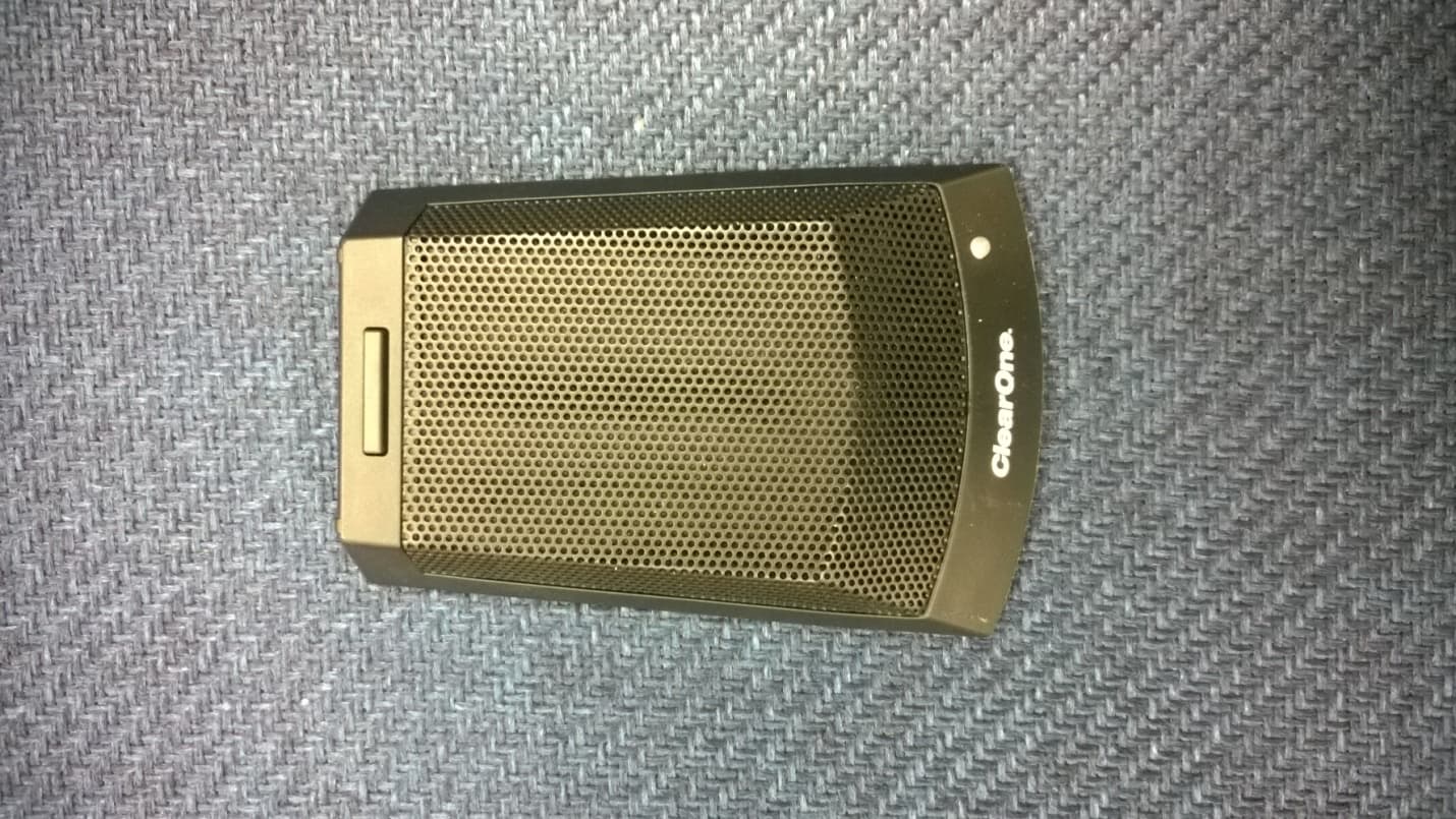
The WS880 wireless microphone system consists of a receiver (WS880 or WS840) and one or more transmitters (WS80T or WS80P or WS80H or WS80B). The WS80T is a “beltpack” transmitter that is designed to be worn by the user. The WS80P is a “podium” transmitter that is designed to be used with a gooseneck microphone. The WS80B is a tabletop boundary microphone transmitter that is designed to be place on a conference room table. The WS80H is a handheld microphone transmitter that is designed to be held by a performer. The WS80T and WS80P do not contain a built-in microphone, but instead have connectors designed to accept various lavalier and gooseneck microphones. The WS80B has a microphone capsule built-in. The WS80H has a threaded removable mic element. These 4 transmitters have identical RF circuits. The transmitters contain a microcontroller that drives the OLED display and handles the user interface functions, and an FPGA that handles the modulation and formatting of the digital audio data from the A/D converter. The data is sent using AES 256 bit encryption. The transmitters use pi/4 DQPSK modulation to encode the audio onto the carrier. The modulation bandwidth is 192kHz. The RF power level is user selectable between 1mW, 10mW, 25mW, or 50mW. The DS80H and DS80P use internal helical antennas. The DS80B uses an internal monopole antenna. The DS80T uses an external monopole antenna. The transmitters transmit on any one of 32 preset channels, selected by the user. These are 812.5kHz apart and cover several frequency ranges. The transmitters are powered by 2 NiMH AA batteries and have a typical run time of approximately 8 hours on a full charge.
Parts List/Tune Up Info
WS880 Tuning Procedure Editing Transmitter Parameters: The easiest and most intuitive way to set the parameters of ClearOne transmitters and receivers is with ClearOne Remote software. Load ClearOne Remote from the disk provided onto a computer running Windows XP or Windows 7 (32 or 64-bit) and connects to the receiver via USB or RS232. Then open ClearOne Remote and select ONLINE. Open The Channel Edit Window: 1) The [Click to Edit] function opens the edit window of the channel you wish to edit. 2) Select the functions you want to edit and enter the parameter. (The various functions are described below.) Click [OK] to save the changes and close the Channel Edit window. 3) You will notice that the [Needs to Sync] alert is lit. This indicates that one or more parameters are in queue in the receiver ready to be downloaded and implemented with the next transmitter Sync of the channel. (1) (2) (3) 1) Click to Edit the channel’s parameters 2) Select the new parameters values and click “OK” to save changes to the receiver 3) The “Need To Sync” alert will light up. Sync the transmitter to apply the selected parameters ClearOne Remote provides the following functions: File: 1. Save a PDF image of the screen. Settings: 2. Phantom Power: A. Turn antenna phantom power on or off. Default = ON. Redundancy: B. Set adjacent pairs of receivers to redundancy mode. Default = OFF. Headphone Mode: C. Toggles the mixed output jack from headphone mode to a balanced line output. Default = Balanced line output. Ethernet Settings: 3. If using Ethernet, assign the proper IP address to the ClearOne Receiver. RF Scan - RF Plot: 4. Shows the RF strength of each antenna in a ClearOne system and shows if there is outside interference. Presets: 5. Save or load preset system parameters configurations. Default = As Ordered. GPIO: 6. Assign contact closure functions and setup for RS232 control. Default = RS232 - Output mutes. Security: 7. Password to prevent unauthorized changes: (Under construction). Default = none. Alerts: 8. Send alerts to authorized personal when preventive maintenance is required of if there is a fault. Default = none. Update System: 9. Checks to see if the system has the most current firmware and provides a wizard for updating the firmware. Help: 10. Tutorials: A. Setting parameters, Antenna Application Guide, etc. About: B. Shows vital statistics for each component of the system Default Transmitter Preamp Gain Settings: Transmitter + Last 4 digits of serial Number Default Transmitter Preamp Gain BLT XXXX +10 dB HH XXXX H18 = 0dB, H13 & H18 = +20dB PDM XXXX +10dB BDM XXXX +20dB
RF Exposure Info
802 N. Twin Oaks Valley Road, Suite 105 • San Marcos, CA 92069 • U.S.A. TEL (760) 471-2100 • FAX (760) 471-2121 http://www.rfexposurelab.com CERTIFICATE OF COMPLIANCE SAR EVALUATION Clearone Communications Dates of Test: November 24, 2014 Edgewater Corporate Park, South Tower 5225 Test Report Number: SAR.20141113 Wiley Post Way, Suite #500 Revision A Salt Lake City, UT 84116 This wireless mobile and/or portable device has been shown to be compliant for localized specific absorption rate (SAR) for uncontrolled environment/general exposure limits specified in ANSI/IEEE Std. C95.1-1992 and had been tested in accordance with the measurement procedures specified in IEEE 1528-2003 and IEC 62209-2 (See test report). I attest to the accuracy of the data. All measurements were performed by myself or were made under my supervision and are correct to the best of my knowledge and belief. I assume full responsibility for the completeness of these measurements and vouch for the qualifications of all persons taking them. RF Exposure Lab, LLC certifies that no party to this application is subject to a denial of Federal benefits that includes FCC benefits pursuant to Section 5301 of the Anti-Drug Abuse Act of 1988, 21 U.S.C. 853(a). Jay M. Moulton Vice President Testing Cert. # 2387.01 FCC ID: FBIHANDHELDMIC IC Certificate: 1970A-HANDHELDMIC Model(s): DS80-H18-C -M500, 910-6003-004-C, DS80-H18-C -M610, 910-6003-003-C Test Sample: Engineering Unit Same as Production Serial Number: Eng 1 Equipment Type: Wireless Handheld Microphone Classification: Portable Transmitter Next to Body TX Frequency Range: 499 – 608 MHz; 614 – 618 MHz Frequency Tolerance: ± 2.5 ppm Maximum RF Output: 500 MHz – 16.99 dBm, 615 MHz – 16.99 dBm Conducted Signal Modulation: FM Antenna Type: Internal Antenna Application Type: Certification FCC Rule Parts: Part 2, 74 KDB Test Methodology: KDB 447498 D01 v05r02 Industry Canada: RSS-102, Safety Code 6 Maximum SAR Value: 0.07 W/kg Reported Separation Distance: 0 mm © 2014 RF Exposure Lab, LLC This report shall not be reproduced except in full without the written approval of RF Exposure Lab, LLC. Report Number: SAR.20141113 Table of Contents 1. Introduction ........................................................................................................................ 3 SAR Definition [5] ................................................................................................................... 4 2. SAR Measurement Setup ................................................................................................... 5 Robotic System ...................................................................................................................... 5 System Hardware ................................................................................................................... 5 System Electronics ................................................................................................................. 6 Probe Measurement System .................................................................................................. 6 3. Probe and Dipole Calibration .............................................................................................14 4. Phantom & Simulating Tissue Specifications .....................................................................15 Head & Body Simulating Mixture Characterization ................................................................15 5. ANSI/IEEE C95.1 – 1992 RF Exposure Limits [2] ..............................................................16 Uncontrolled Environment .....................................................................................................16 Controlled Environment .........................................................................................................16 6. Measurement Uncertainty .................................................................................................17 7. System Validation..............................................................................................................18 Tissue Verification .................................................................................................................18 Test System Verification ........................................................................................................18 8. SAR Test Data Summary ..................................................................................................19 Procedures Used To Establish Test Signal ...........................................................................19 Device Test Condition ...........................................................................................................19 SAR Data Summary – Body ..................................................................................................21 9. Test Equipment List ...........................................................................................................22 10. Conclusion ....................................................................................................................23 11. References ....................................................................................................................24 Appendix A – System Validation Plots and Data .......................................................................25 Appendix B – SAR Test Data Plots ...........................................................................................30 Appendix C – SAR Test Setup Photos ......................................................................................33 Appendix D – Probe Calibration Data Sheets ............................................................................35 Appendix E – Dipole Calibration Data Sheets ...........................................................................47 Appendix F – Phantom Calibration Data Sheets ..............................................................…
Text truncated - open the document above for the full version.
Test Report
FCC PART 74 LOW POWER LICENSED TRANSMITTER TEST REPORT APPLICANT CLEARONE INC. EDGEWATER CORPORATE PARK, SOUTH TOWER 5225 WILEY POST WAY, SUITE # 500 SALT LAKE CITY UTAH 84116 USA FCC ID FBIHANDHELDMIC MODEL NUMBER DS80-H18-C-M500, 910-6003-004-C, DS80-H18- C-M610, 910-6003-003-C PRODUCT DESCRIPTION HANDHELD WIRELESS MICROPHONE STANDARD APPLIED CFR 47 Part 74.801 DATE SAMPLE RECEIVED 9/15/2014 DATE TESTED 9/22/2014 TESTED BY Sid Sanders APPROVED BY Cory Leverett TIMCO REPORT NO. 16 31 AUT14TestReport Rev1.docx TEST RESULTS PASS FAIL THE ATTACHED REPORT SHALL NOT BE REPRODUCED EXCEPT IN FULL WITHOUT THE WRITTEN APPROVAL OF TIMCO ENGINEERING, INC. 849 NW STATE ROAD 45 NEWBERRY, FL 32669 USA PH: 888.472.2424 OR 352.472.5500 FAX: 352.472.2030 EMAIL: [email protected] HTTP://WWW.TIMCOENGR.COM Applicant: CLEARONE INC. FCC ID: FBIHANDHELDMIC REPORT: C\CLEARONE_FBI\1631AUT14\16 31AUT14TestReport Rev1.docx Page 2 of 19 TABLE OF CONTENTS GENERAL REMARKS ............................................................................................... 3 GENERAL INFORMATION......................................................................................... 4 TEST PROCEDURES ................................................................................................ 6 TEST REPORT SUMMARY ......................................................................................... 7 RF POWER OUTPUT ................................................................................................ 8 MODULATION CHARACTERISTICS ............................................................................ 9 MODULATION CHARACTERISTICS ............................................................................ 9 OCCUPIED BANDWIDTH ......................................................................................... 9 20 dB PLOT ................................................................................................................ 10 20 dB PLOT ................................................................................................................ 11 FIELD STRENGTH OF SPURIOUS EMISSIONS........................................................... 12 FIELD STRENGTH OF SPURIOUS EMISSIONS TEST SETUP PHOTO .............................. 13 FIELD STRENGTH OF SPURIOUS EMISSIONS........................................................... 14 FIELD STRENGTH OF SPURIOUS EMISSIONS........................................................... 15 FIELD STRENGTH OF SPURIOUS EMISSIONS........................................................... 16 SPURIOUS EMISSIONS AT ANTENNA TERMINALS (CONDUCTED) ............................... 17 FREQUENCY STABILITY ........................................................................................ 18 EMC EQUIPMENT LIST .......................................................................................... 19 Applicant: CLEARONE INC. FCC ID: FBIHANDHELDMIC REPORT: C\CLEARONE_FBI\1631AUT14\16 31AUT14TestReport Rev1.docx Page 3 of 19 GENERAL REMARKS The attached report shall not be reproduced except in full without the written permission of Timco Engineering Inc. The test results relate only to the items tested. Summary The device under test does: fulfill the general approval requirements as identified in this test report not fulfill the general approval requirements as identified in this test report Attestations This equipment has been tested in accordance with the standards identified in this test report. To the best of my knowledge and belief, these tests were performed using the measurement procedures described in this report. All instrumentation and accessories used to test products for compliance to the indicated standards are calibrated regularly in accordance with ISO 17025 requirements. I attest that the necessary measurements were made, under my supervision, at: Timco Engineering Inc. 849 NW State Road 45 Newberry, Fl 32669 Authorized Signatory Name: Project Manager Name Engineering Project Manager Date: 10/21/2014 Table of contents Applicant: CLEARONE INC. FCC ID: FBIHANDHELDMIC REPORT: C\CLEARONE_FBI\1631AUT14\16 31AUT14TestReport Rev1.docx Page 4 of 19 GENERAL INFORMATION RULES FCC PART 2.1033 EUT TECHNICAL DESCRIPTION EUT Description HANDHELD WIRELESS MICROPHONE FCC ID FBIHANDHELD Model Number DS80-H18-C-M500, 910-6003-004-C, DS80-H1`8- C-M610, 910-6003-003-C Modulation CQPSK Type of Emission 156K0F1D Frequency Range 499-608MHz & 614-618MHz Test Frequencies 499, 511.58, 605.40, 614.35, & 617.60MHz Maximum Output Power 30milliWatts EUT Power Source 110–120Vac/50– 60Hz DC Power Battery Operated Exclusively Test Item Prototype Pre-Production Production Type of Equipment Fixed Mobile Portable Table of contents Applicant: CLEARONE INC. FCC ID: FBIHANDHELDMIC REPORT: C\CLEARONE_FBI\1631AUT14\16 31AUT14TestReport Rev1.docx Page 5 of 19 GENERAL INFORMATION Test Facility Timco Engineering, Inc. 849 NW State Road 45, Newberry, FL 32669 Test Condition The temperature was 24-26ºC with a relative humidity of 50-60%. Modifications None Test Exercise (e.g software description, test signal, etc.) The EUT was operated in its normal mode of operation. Applicable Standards ANSI/TIA 603-C:2010, FCC CFR 47 Parts 2 and 74 Table of contents Applicant: CLEARONE INC. FCC ID: FBIHANDHELDMIC REPORT: C\CLEARONE_FBI\1631AUT14\16 31AUT14TestReport Rev1.docx Page 6 of 19 TEST PROCEDURES Power Line Conducted Interference: The procedure used was ANSI/TIA 603-C:2004 using a 50uH LISN. Both lines were observed with the UUT transmitting. The bandwidth of the spectrum analyzer was 10 kHz with an appropriate sweep speed. Bandwidth 20 dB: The measurements were made with the spectrum analyzer's resolution bandwidth (RBW) = 1 MHz and the video bandwidth (VBW) = 3 MHz and the span set as shown on plot. Power Output: For a device with a fixed antenna, RF power is measured as ERP as the antenna is permanently attached. The substitution method was used as described …
Text truncated - open the document above for the full version.
Contact Information
Applicant
Derek Graham(Sr. V.P. of Research and Development)
Technical Contact
Timco Engineering, Inc.Sid Sanders
[email protected]888-472-2424
849 NW State Road 45 · Newberry, Florida · United States
Non-Technical Contact
Timco Engineering, Inc.Sharon Hoffman
[email protected]888-472-2424
Test Firm
Timco Engineering, Inc.Bruno Clavier
Technical Specifications
| # | Rule Parts | Frequency Range | Power Output | Emission | Tolerance |
|---|---|---|---|---|---|
| 2 | 74.861 | 614 MHz - 618 MHz | 30.00 mW | 156KF1D | 0.599 ppm |
Other Applications from ClearOne, Inc.
FBITABLETOP
Jan 01, 2015TABLE TOP WIRELESS MICROPHONE
Equipment Class
TBC - Licensed Broadcast Station Transmitter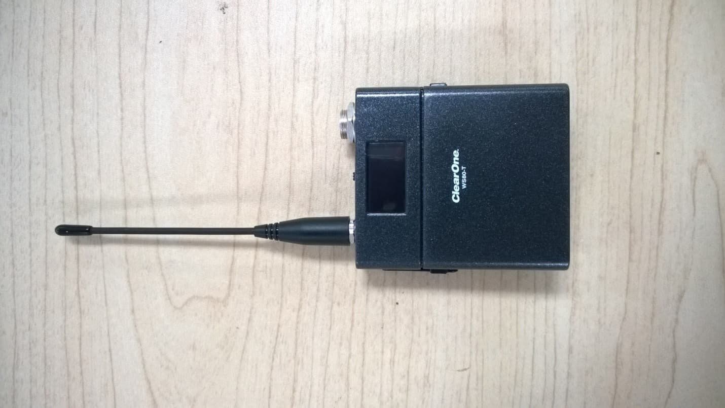
FBIBELTPACK
Dec 29, 2014BELTPACK WIRELESS MICROPHONE
Equipment Class
TBC - Licensed Broadcast Station Transmitter
FBIGOOSENECK
Dec 29, 2014GOOSENECK WIRELESS MICROPHONE
Equipment Class
TBC - Licensed Broadcast Station Transmitter
FBIDIALER
May 26, 2010Interact DIALER-W
Equipment Class
DTS - Digital Transmission System
FBICOM
May 26, 2010Interact COM-W
Equipment Class
DTS - Digital Transmission System