FBR-RSPDL800BAudience Response Keypad
Fleetwood Group Inc
Click to zoom
Application Details
- Equipment Class
- DSC - Part 15 Security/Remote Control Transmitter
- Date of Grant
- Mar 15, 1999
- Application Purpose
- Original Equipment
- Date of Application
- Oct 30, 1998
- Equipment Note
- Audience Response Keypad
- Frequency Range
- 345.00000000 - 370.00000000
- Company
- Fleetwood Group Inc
- Country
- United States
Documents & Files
Document Text
Text extracted from the exhibit documents filed with the FCC. Open a document above to read the original.
Users Manual
Fleetwood Group Inc. FCC ID: FBR-DL800B User Manual Page 1 of 4 File Name: DLMAN.DOC Date: 07/13/01 Reply® DL Response Keypad Model CRS10000 Users Manual Purpose of the Keypad The Reply® DL Model CRS10000 Keypad is a wireless portable device that makes it possible for a number of people to participate interactively in a class situation or group meeting. The product accomplishes this by sending keypad switch closure information from the keypad to a base unit which employs a wireless transceiver to receive the keypad signal. These signals are processed by the base unit and delivered to a host computer which allows the responses to be stored, analyzed and if desired displayed on a video projector for feedback to the group showing the results of their participation. As such, the product is very similar to another Fleetwood product, the CRS1200. The Model CRS10000 adds to the Model CRS1200 by incorporating an 800 MHz wireless microphone circuit that allows a participant at a remote site to speak into the keypad and communicate with an instructor through a phone line connection. This adds the dimension of allowing verbal interaction from a remote site with an instructor. Description of the Keypad The Reply Model CRS10000 Keypad is housed in a plastic enclosure similar in appearance to a calculator. It is powered by an internal 9 volt alkaline battery with no external wires or electrical connections. The keypad uses a membrane switch panel for numeric entry and a 7 segment LED display for entry display to the user. The keypad uses a synthesized transceiver compliant with FCC Part 15 Subpart B and C. An integrated microphone and talk request button provide an audio function for use in multiple site applications. The wireless microphone portion of the device is compliant with and approved under Part 74. Using the Keypad To use a Reply® DL Keypad, a corresponding channel Reply® DL base unit must be active and under control of an application running on a local or remote host computer. This is usually the responsibility a local facilitator in cooperation with host site staff in a distance learning environment. A program on a host site computer under control of the instructor or facilitator determines when responses from the keypads are to be received and when control of the wireless microphone in the keypads is required. Typically this program will deliver a number of informational screens via satellite or other video transmission method on a video projection system and then will present a question screen. The participants with keypads will then be instructed to respond using the numeric keys on the keypad. A user holding a keypad responds by pressing one of the keys and the corresponding number will indicate on the 7 segment LED Fleetwood Group Inc. FCC ID: FBR-DL800B User Manual Page 2 of 4 File Name: DLMAN.DOC Date: 07/13/01 display. When interrogated by the base via the 216 MHz link, the keypad sends the key information to the base in a 10 millisecond duration signal from the 345 MHz transmitter. When the 216 MHz signal responds with an appropriate state of the acknowledge bit for the keypad, the keypad turns back off and awaits the next key press. This sequence takes on the average between one and two seconds. If the keypad LED winks and comes back on, the signal was not received by the base and the keypad will retry the next time it is interrogated (typically about 2.5 seconds). The keypad spends most of its time in a sleeping mode conserving the battery and allowing for thousands of transmissions. If a user wishes to talk to the instructor the user presses the “Talking Face” key on the keypad. This transmits the microphone request to the base unit and via a data modem on the base to the host to notify the instructor. When the instructor is ready to take the request, an activation signal is sent out via the data modem to the remote site base unit which in turn commands the keypad to activate the microphone. In Case of Difficulty The Reply® Model CRS10000 Keypads are built using the latest technology and high reliability components. There are very few things the keypad user can do wrong to cause a failure, but in the unlikely event responses are not being received by the base and passed on to the personal computer, the next pages detail procedures that can help identify the source of the problem: Fleetwood Group Inc. FCC ID: FBR-DL800B User Manual Page 3 of 4 File Name: DLMAN.DOC Date: 07/13/01 CHART 1 Keypad Communication Checkout Are some keypads being received? Press a number on a non-working keypad Does its display light? Replace bad battery and retry or keypad defective - return to factory No Defective base or PC software problem. See Reply Base Manual Does its display flash at a rapid rate? Yes Replace bad battery and retry keypad Yes Does its display stay on solid (never wink)? No Keypad defective Return to factory for service Does display wink at a regular rate (between .5 and 2.5 seconds? Yes No Keypad transmit problem Yes Keypad receive problem Yes No No Fleetwood Group Inc. FCC ID: FBR-DL800B User Manual Page 4 of 4 File Name: DLMAN.DOC Date: 07/13/01 CHART 2 Keypad Audio Checkout Defective base or PC software problem. See Reply DL Manual Did the "Wait" LED light when the "Talk" button was pressed? Keypad defective Return to factory for service No Did the "Wait" LED transition from blinking to solid? Yes Did the "Talk" LED come on after the solid "Wait"? Yes Did other keypads transistion from blinking to solid? No No No Was acceptable keypad audio received at the DL host? Yes Satisfactory Yes Does the audio work properly on some keypads No No
Cover Letter(s)
Fleetwood Group Inc. FCC ID: FBR-DL800B Application Statement Page 1 of 1 File Name: DLAPP.DOC Date: 07/13/01 October 31, 1998 Federal Communications Commission 7435 Oakland Mills Rd. Columbia, MD 21046 Dear Examiner: This application is one of two required for FCC ID: FBR-RSPDL800B, an improved version of a previously approved product with FCC ID: FBR-RSPDL800A. The two applications are as follows: one is for Part 15 Subpart B and C and one is for Part 74. It is the same product in appearance and functionality as the previously approved product but there have been circuitry changes internally for product improvement. These changes in the Part 15 applicable parts of the device involve using new RF components and synthesizer technology to provide multi-channel capability (same frequencies used as the previous product) and to reduce cost. Performance is the same as with the previous design for compatibility with older systems. The Part 74 (wireless microphone aspect of the product) circuits have not been changed but because of change of the FCC ID required for the Part 15 redesign, a new application is submitted. The product has been re-tested by Elite Electronic Engineering Company to confirm ongoing compliance. Documents showing the new schematic and circuit board appearance as well as all other relevant documents are supplied with this application. Sincerely, Harry Derks Manager of Electronics Engineering Fleetwood Group Inc. FLEETWOOD
Cover Letter(s)
Fleetwood Group Inc. 731 Confirmation No. EA92168 Form 731 Change Request Page 1 of 1 File Name: DL15CHG.DOC Date: 07/11/01 November 10, 1998 Federal Communications Commission 7435 Oakland Mills Rd. Columbia, MD 21046 Subject:FCC ID correction for 731 form Dear Examiner: This letter is to request correction to an electronic form 731 as follows: 731 Confirmation Number EA92168 FCC ID incorrectly entered on electronic form 731:FBRRSPDL800B Intended FCC ID to agree with exhibits:FBR-RSPDL800B Also the following exhibits had the following error in FCC ID at the bottom of their pages: In each case FBR-DL800B should be FBR-RSPDL800B. Confidentiality Request Letter Application Letter Test Setup Photos User Manual Please let me know if these exhibits should be resubmitted to correct this discrepancy. Sincerely, Harry Derks Manager of Electronics Engineering Fleetwood Group Inc. FLEETWOOD
Cover Letter(s)
Fleetwood Group Inc. FCC ID: FBR-DL800B Confidentiality Request Page 1 of 1 File Name: DLREQA.DOC Date: 07/10/01 November 30, 1998 Federal Communications Commission 7435 Oakland Mills Rd. Columbia, MD 21046 Dear Sir or Madam: On the advice of our patent attorney, we would like to have the following exhibits of our application FCC ID: FBR-RSPDL800B held confidential pursuant to Section .457(d) of the Rules: Schematics Block diagrams If you have any questions, please call me at 616-820-8237 or fax to 616-820-8300. We look forward to your prompt action on this application. Sincerely, Harry Derks Manager of Electronics Engineering Fleetwood Group, Inc. FLEETWOOD
External Photos
Fleetwood Group Inc. FCC ID: FBR-RSPDL800B External Photos Page 1 of 1 File Name: DLPHOTE.DOC Date: 07/13/01
ID Label/Location Info
E - No.: Title: Part No.: Material / Color: Drw'n:Scale: Date:Chk'd: Date:Overall Size: Sheet:of Electronics Division Fleetwood Group, Inc. P.O. Box 1259; Holland, MI 49422-1259 11832 James St; Holland, MI 49424 Phone: 616 396-1142 / Fax: 616 820-8300 Blue Text on White Gloss 60# Stock 1" x 2.50" Label 0.125" Corner Radius MODEL: CRS10000 FCC ID: FBR-RSPDL800B Data TX 358.5 MHz RX 218.0125 MHz Audio TX 800-805 MHz U.S. PATENT NO. Re. 35,449. OTHER US AND FOREIGN PATENTS PENDING Fleetwood Group, Inc. Electronics Division Holland, Michigan 49424 THIS DEVICE COMPLIES WITH PART 15 AND PART 74 OF THE FCC RULES. OPERATION IS SUBJECT TO THE FOLLOWING TWO CONDITIONS: (1) THIS DEVICE MAY NOT CAUSE HARMFUL INTERFERENCE, AND (2) THIS DEVICE MUST ACCEPT ANY INTERFERENCE RECEIVED, INCLUDING INTERFERENCE THAT MAY CAUSE UNDESIRED OPERATION. CH4 1:1 EA 10/15/98 1 1 Reply® DL Keypad Label FCC ID: FBR-RSPDL800B HD10/15/98
Operational Description
Fleetwood Group Inc. FCC ID: FBR-DL800B Operational Description Page 1 of 3 File Name: DLOPER.DOC Date: 07/02/01 Reply® DL Keypad Model CRS10000 Operational Description (Part 74) System Description: The Fleetwood Reply DL Wireless Response System is designed to provide a means of interactivity in a distance learning (multiple site) broadcast setting. This interactivity is accomplished by the Reply DL system in two ways: (1) by participant keypad entries (switch closure information) and (2) audio interaction via the internal wireless microphone. The keypad entries (numeric keys) are sent via modem to the host location to be incorporated in bar graphs, pie charts, or other graphical displays and the audio from the keypad when activated is fed to the host location via an analog phone line for rebroadcast to enable the other sites to hear comments and questions from other participants. The typical remote site may consist of as few as 6 to as many as 250 keypad units. Operation: During a normal session with the response system, a typical sequence may occur as follows: 1. Instruct the participants on the usage of the keypad units. 2. Ask a question and allow enough time (at least 10 seconds) for all participants to respond. 3. Observe the results on the PC screen and optionally save the results for later analysis if desired. 4. Proceed and repeat the process on the next question. 5. When a keypad talk request from a remote site is received, if desired activate the keypad microphone and broadcast the participant audio to all sites. 5. Continue until all questions are completed. General Characteristics: The base and keypad units are integrated by three functional subsystems. KEYPAD:BASE: CONTROL SIGNALS: 1. Address receiver⇐Address transmitter. 2. Response transmitterÞResponse receiver. AUDIO LINK: 1. UHF audio link transmitterÞAudio link receiver. Fleetwood Group Inc. FCC ID: FBR-DL800B Operational Description Page 2 of 3 File Name: DLOPER.DOC Date: 07/02/01 WIRELESS MICROPHONE LINK TRANSMITTER (KEYPAD): The voice link transmitter in the keypad allows microphone audio to be sent to the base unit to be sent in turn to the host site for rebroadcast to other remote sites. The transmitter is a low power device which has four subparts as referenced in the schematic diagram. • Synthesizer: The frequency synthesizer U7 locks the transmitter oscillator to the reference oscillator on one of four channels. When power is first applied to the link transmitter, information from U4 microprocessor is applied to synthesizer U7. The first data is channel information as preset by a keypad entry (channels 1-4). This information is loaded via a 3 wire serial interface to U7. The transmitter frequencies are preset by channel selection, and by the action of the RF programmable divider within U7. Operational commands (Atx-enable, Ser. Data, Ser. Clock) are also sent via the 3 wire control lines to U7. The reference oscillator in U4 is set to a frequency of 16.1 MHz. by crystal Y3. The frequency is adjusted by a voltage tuned varicap (VC2). The 16.1 MHz. signal is presented to the reference divider chain in U7 which is in a preset divide state. The Voltage Controlled Oscillator (VCO) signal from Q24, is applied to the main frequency divider of U7 which is preprogrammed by the channel selected (1-4). The VCO’s output signal, and the 16.1 MHz crystal output signal are each divided down to a common comparison frequency (see fig. 1). Both signals are then applied to the phase comparator of U7 to generate a VCO control voltage proportional to the frequency difference. In the VCO locked state, the two frequencies are equal and the VCO control voltage is stable. If frequency changes occur in the VCO, the control voltage will change to correct for the shift. The output control voltage from the phase comparator is passed thru a filter (C66&R96), and then to varicap VC4 which tunes and maintains the VCO to the desired frequency. FIG. 1 REPLY DL KEYPAD AUDIO TRANSMITTER FREQUENCY OPTIONS Formula f Mf R out xtl = Key f out = Output Frequency M = Multiplier f xtl = Crystal Frequency = 16.1 MHZ R = Reference Divider = 161 (Reference Frequency = 100 KHz) ChannelMultiplierOutput Frequency Fleetwood Group Inc. FCC ID: FBR-DL800B Operational Description Page 3 of 3 File Name: DLOPER.DOC Date: 07/02/01 18002800.2 MHZ 28023802.3 MHZ 38049804.9 MHZ 48033803.3 MHZ • Transmitter: Transmitter amplifier U6 is a monolithic integrated circuit which operates from a 5 Vdc single voltage supply. U6 has internal current regulation which minimizes gain changes over temperature. The transmitter is designed to operate over the range of 800.2 - 804.9 MHz. in continuous mode and conforms to FCC rules part 74 subpart h low power radiation and harmonic content. The 5V dc power is turned on and off by the action of microcontroller U4. When activated, the RF signal from the VCO is applied to the input of the transmitter's low pass filter- LPF (R100, L12,C71&C72). This filter is designed to prevent harmonic energy from reaching U6 from the VCO. The LPF is also configured to maintain a constant load to the input of amplifier U6 and thus ensure stability. The amplified signal of U6 is applied to the output LPF which functions the same as the input filter. To ensure signal purity a second LP filter is employed to help remove any possible harmonic content generated by U6 (C76,C77&L13). This LPF also is designed to match the output circuit of U6. The output signal from the second LP filter is applied to a tuned harmonic trap. This trap (C78,C81&L14), is designed to remove second harmonic energy from U6 and keep it from reaching the antenna. • •• •Antenna: The antenna tuner network(C82&C83) is designed to match the impedance of the transmitter to that of the antenna for best RF energy transfer. This network also performs the tuning of the antenna. The antenna is configured as an horizontal 1/4 λ circular radiator over a ground plane. This configuration creates cir…
Text truncated - open the document above for the full version.
Operational Description
Fleetwood Group Inc. FCC ID: FBR-RSPDL800B Operational Description Page 1 of 4 File Name: DLDESC.DOC Date: 07/02/01 Reply® DL Keypad Model CRS10000 Operational Description (Part 15) Introduction General Characteristics: Enclosure:Each keypad is housed in an A.B.S. plastic molded enclosure. Overall size is approximately 6.7” L x 3” W x 1.4” H. Weight is approximately 8 oz. User Interface: Membrane keyboard with tactile feedback for response entry. Ten digit keys (1-10, A-E, Yes/No) and Enter, Clear, Talk, and Login keys allow intuitive entry of responses. A seven segment LED display provides immediate feedback of the user response and keypad status. A green LED provides talk status and a red LED provides wait status for the wireless microphone. Supply:Battery powered using readily available 9 Volt alkaline battery. Low battery detection and indication through rapidly flashing the LED provides feedback to user and to base unit. Keypads shutdown automatically between responses to extend battery life. Technology:Entirely solid state using a CMOS microcontroller. Receive and transmit are fully synthesized and crystal referenced. The receiver incorporates dual conversion superheterodyne FM design for superior sensitivity, stability, and selectivity. The transmitter is frequency locked to the reference and is FM modulated. The wireless microphone section is also synthesized and frequency locked to the crystal reference. General System Description The Reply® DL Keypad monitors user input from the membrane switch panel, displays the key value pressed on the LED display, and transmits the key value to the base unit. The keypad is powered by a 9 volt alkaline battery. The operating voltage is regulated to 5 volts DC. To conserve battery current the keypad is shut down automatically when not being used. A hardware reset circuit (RC discharge) guarantees the keypad will be shut down even in the rare event that the microprocessor malfunctions. The five volt regulator provides a logic signal to alert the microcontroller when battery voltage nears 6.5 volts and is in need of replacement. If an option is enabled, the keypad can send low battery status to the base unit. A system clock frequency of 10.200 MHz is provided by an external crystal circuit on the microcontroller. The same crystal reference is used for both microcontroller and RF portions of the keypad. Key press inputs are read through a 14 key switch matrix. The matrix is configured in four columns (microcontroller inputs) and four rows (microcontroller outputs). The matrix columns are pulled up to 9 volts via the reset circuit so when a key is pressed, the primary regulator and Fleetwood Group Inc. FCC ID: FBR-RSPDL800B Operational Description Page 2 of 4 File Name: DLDESC.DOC Date: 07/02/01 microcontroller are powered up. The microcontroller then reads the switch matrix by alternately grounding each row until it sees a 'low' at the column input. Keypad configurations such as keypad address and channel number are stored in on-board EEPROM. Receiver Theory of Operation Introduction to Receiver Operation The Control Receiver (CRX) is located within the CRS 10000 handheld communicator. The receiver is activated when the user enters a digit from the integral keypad. The receiver diagram is included in the block diagram exhibit. The receiver operates with Frequency Shift Keyed (FSK) binary data with +/- 5kHz nominal deviation. Receiver Frequency Plan The receiver is a double conversion super-heterodyne system with a 1 st IF of 10.655 MHz and a 2 nd IF of 455 KHz. It uses a 10.2 MHz crystal oscillator for the 2 nd LO, processor clock, and as a reference signal for the synthesized 1 st LO. The eight channels and the respective 1 st LO frequencies are listed below: Channel Number Carrier FrequencyFirst LO Frequency 1216.0125 MHz205.3575 MHz 2219.0125208.3575 3217.0125206.3575 4218.0125207.3575 5216.5125205.8575 6217.5125208.8575 7219.5125206.8575 8218.5125207.8575 The synthesizer uses an internal reference frequency of approximately 50 kHz. Receiver Block Diagram The following explains the receiver block diagram exhibit: The 216 to 219 MHz signal is first received by the printed antenna followed by a two-pole band-pass filter, and low noise amplifier (U102a). Next, potential interference from the keypad transmitter is removed in the 345 to 370 MHz band reject filter (FL3), followed by additional gain in U102b. The output of U102b is impedance-matched to the 1 st conversion mixer (M1) with a transformer (which is realized with L107, L109, and C117 – Figure 2). The output of M1 (10.655 MHz) is amplified by A1 and filtered by FL4. Next, the signal is converted to 455 KHz in M2, amplified by A2, and band-pass-filtered in FL5. The Fleetwood Group Inc. FCC ID: FBR-RSPDL800B Operational Description Page 3 of 4 File Name: DLDESC.DOC Date: 07/02/01 sequence of A3, A4, and M3 form a traditional limiter/discriminator that provides a 2Vp-p detected signal. The detected signal is low-pass filtered and AC coupled in FL6 and sent to a threshold comparator as realized in U202 to form a conditioned signal out to send to the microcontroller. Transmitter Theory of Operation Introduction to Transmitter Operation The Control Transmitter (CTX) is located within the CRS 1200 handheld keypad. The transmitter is activated within assigned 10mS slots with slots as determined in the fixed base station. After the user enters a digit in the keypad the keypad receiver is activated and subsequently receives time slot information, following which the CTX is turned on within the appropriate slot. The CTX is diagrammed in Figure 1, with schematic shown in Figure 2. Transmitted Waveform Description The Control (CTX) transmitter is a Frequency Shift Keyed (FSK) binary data transmitter, which is activated by a keypress for a period of 10 mS. It has a minimum interval of 500 milliseconds between transmit intervals. As such, the legal peak power is increased by 20 dB since the CTX has a du…
Text truncated - open the document above for the full version.
Test Setup Photos
Fleetwood Group Inc. FCC ID: FBR-DL800B Test Setup Photos Page 1 of 1 File Name: DLSET.DOC Date: 07/13/01
Contact Information
Applicant
Brian Harvey(VP Engineering, Electronics)
Technical Contact
Fleetwood Group Inc.Harry G Derks
[email protected]616-820-8237
11832 James St. · Holland, Michigan · United States
Non-Technical Contact
Fleetwood Group Inc.Nicholas W Medendorp
[email protected]616-820-8250
Test Firm
Elite Electronic Engineering Co.Daniel Crowder
Technical Specifications
| # | Rule Parts | Frequency Range | Power Output |
|---|---|---|---|
| 1 | 15C | 345 MHz - 370 MHz | - |
Other Applications from Fleetwood Group Inc
FBR5900
Mar 06, 2026Low Power BLE Transceiver
Equipment Class
DTS - Digital Transmission SystemFBR5820
Dec 02, 2025Low Power BLE Transceiver
Equipment Class
DTS - Digital Transmission SystemFBR-HR350C-1
Apr 04, 2024Collar Mounted Transceiver
Equipment Class
TNT - Licensed Non-Broadcast Transmitter Worn on BodyFBR-HR350R-1
Apr 04, 2024Handheld Remote Transceiver
Equipment Class
TNT - Licensed Non-Broadcast Transmitter Worn on Body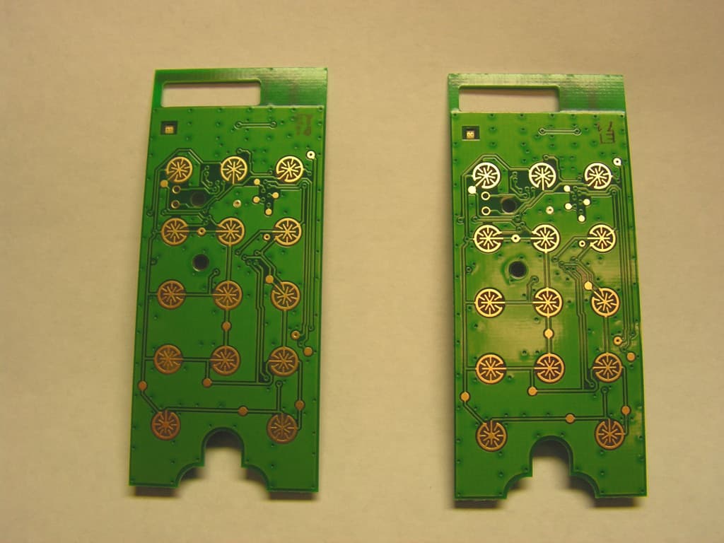
FBRE240D
Jan 10, 2013Low Power RF Module
Equipment Class
DXT - Part 15 Low Power Transceiver, Rx Verified