FBR-TX216SYN-2Addressing transmitter for group response keypads
Fleetwood Group Inc
Click to zoom
Application Details
- Equipment Class
- TNB - Licensed Non-Broadcast Station Transmitter
- Date of Grant
- Feb 09, 2000
- Application Purpose
- Original Equipment
- Date of Application
- Nov 16, 1999
- Equipment Note
- Addressing transmitter for group response keypads
- Frequency Range
- 216.00000000 - 220.00000000
- Company
- Fleetwood Group Inc
- Country
- United States
Documents & Files
Document Text
Text extracted from the exhibit documents filed with the FCC. Open a document above to read the original.
Users Manual
Fleetwood Group Inc. FCC ID: FBR-TX216SYN-2 User Manual Page 1 of 2 File Name: TXMAN.DOC Date: 11/15/99 CRS920 User Manual System Setup 1. Unpack the CRS920 base unit and set it on a table or available surface in the vicinity of where the CRS1200 Response Keypads will be used. 2. Plug the AC power module into the CRS920 DC input jack. 3. Plug the AC line cord from the power module into a 115 VAC power circuit. 4. Turn on the power switch of the CRS920 base unit. 3.Plug either the RJ45 supplied cable or a standard DB9 to DB9 RS232 cable into a COM port (usually Com1 or Com2). 5.Open the carrying case containing the response keypads and distribute them to the participants. 6.Turn on the computer and start the application software to control the base unit to poll for keypad responses. Operation 1Instruct the participants on the usage of the response keypads and procedure for responding. 2.Ask a question and allow enough time (at least 10 seconds) for all participants to respond. 3. Observe the results on the screen and optionally save the results for later analysis if desired. 4. Proceed and repeat the process for the next question. 5. Continue until all questions are completed. 6.Collect response keypads from the participants and return them to their carrying case. 7.Analyze the responses for the period and run printouts if desired. System Shutdown 1.Turn off the power to the computer. 2. Turn off the power to the CRS920 base unit. 3. Unplug the data cable from the computer and store it in its carrying case. 4. Unplug the AC line cord from the power module and store both in the carrying case. 5. Store the CRS920 in its carrying case. 6. Collect the keypads and return them to their carrying case. 7.The system is now ready for transporting. Note: FCC ID: FBR-TX216SYN-2 is one of several components used in the CRS920. The Model TX216SYN is contained in the CRS920 hence the inclusion of the CRS920 User Manual section. The transmitter in this product is FCC Part 90.217 Type accepted and the receiver is FCC Part 15 approved. Operation is subject to these conditions: 1) This device may not cause harmful interference. 2) This device must accept interference that causes faulty operation. Fleetwood Group Inc. FCC ID: FBR-TX216SYN-2 User Manual Page 2 of 2 File Name: TXMAN.DOC Date: 11/15/99 CRS 920 RS232 cable Reply® Response System Typical Setup Instructor or Facilitator Location Participants with CRS1200 Keypads Personal Computer TX216SYN is in here
Cover Letter(s)
Fleetwood Group Inc. FCC ID: FBR-TX216SYN-2 Application Statement Page 1 of 1 File Name: TX216APP.DOC Date: 11/15/99 November 15, 1999 Federal Communications Commission 7435 Oakland Mills Rd. Columbia, MD 21046 Dear Examiner: This application for FCC ID: FBR-TX216SYN-2 is for a new version of a previously approved product with FCC ID: FBR-5FKRSPTX-1. It is the same product in functionality as the previously approved product but there have been circuitry changes for product improvement. These changes consist of using new RF components and synthesizer technology to provide multi-channel capability (same frequencies used as the previous product) and to reduce cost. Performance including system timings is the same as the previous design for compatibility with older systems. The product has been tested by D.L.S. Electronic Systems Inc. to confirm compliance. Sincerely, Harry Derks Manager of Electronics Engineering Fleetwood Group Inc. FLEETWOOD
Cover Letter(s)
Fleetwood Group Inc. FCC ID: FBR-TX216SYN-2 Confidentiality Request Page 1 of 1 File Name: TXREQ.DOC Date: 11/15/99 November 2, 1999 Federal Communications Commission 7435 Oakland Mills Rd. Columbia, MD 21046 Dear Sir or Madam: On the advice of our patent attorney, we would like to have the following exhibits of our application FCC ID: FBR-TX216SYN-2 held confidential pursuant to Section .457(d) of the Rules: Schematics Block diagrams If you have any questions, please call me at 616-820-8237 or fax to 616-820-8300. We look forward to your prompt action on this application. Sincerely, Harry Derks Manager of Electronics Engineering Fleetwood Group, Inc. FLEETWOOD
ID Label/Location Info
Fleetwood Group Inc. FCC ID: FBR-TX216SYN-2 FCC ID Label Page 1 of 1 File Name: TXLABEL.DOC Date: 11/15/99 Reply® Transmitter Model TX216SYN FCC ID: FBR-TX216SYN-2 FCC ID LABEL FCC ID LABEL LOCATION EQUIPMENT IDENTIFICATION LABELING Due to the size of the module, the label contains the FCC ID only. The User’s Manual contains the statement as follows: The transmitter in this product is FCC Part 90.217 Type accepted. Operation is subject to these conditions: 1) This device may not cause harmful interference. 2) This device must accept interference that causes faulty operation. 3.56”
Internal Photos
Fleetwood Group Inc. FCC ID: FBR-TX216SYN-2 Photos Page 1 of 1 File Name: TXPHOTO.DOC Date: 11/15/99 Reply® Transmitter Model TX216SYN FCC ID: FBR-TX216SYN-2 PHOTOS Component Side Bottom Side
Operational Description
Fleetwood Group Inc. FCC ID: FBR-TX216SYN-2 Operational Description Page 1 of 3 File Name: TXDESC.DOC Date: 11/15/99 Reply® Transmitter Model TX216SYN FCC ID: FBR-TX216SYN-2 Operational Description Introduction The Fleetwood Model TX216SYN is a low power transmitter designed for operating in the frequency range from 216 to 220 MHz to be type accepted for operation under Part 90.259. The transmitter is manufactured as a printed circuit module approximately 2 inches by 3 9/16 inches using surface mount components. This module replaces an earlier design originally approved in 1989 (FCC ID: FBR-5FKRSPTX-1) which was enclosed in a larger case, crystal controlled on a single frequency, and used more costly through hole technology for manufacture. The new design utilizes surface mount technology and state of the art synthesizer design providing cost reduction in addition to allowing operation on frequencies in the 216-220 MHz range. General System Description The Fleetwood Model TX216SYN transmitter is used as a part of a base system which communicates with a number of response keypads (approved under separate applications) to allow feedback from participants in a meeting or classroom situation to be collected and displayed on a personal computer running a controlling application. The base unit composes and sends via the Model TX216SYN transmitter an addressing signal to the keypads which determines when they will transmit their entry back to the base unit. The keypad entries are typically one of ten keys on a membrane switch panel on the keypad. Transmitter Theory of Operation The Model TX216SYN transmitter is designed using a National LMX2313 Frequency Synthesizer IC. A crystal controlled oscillator Q4, Y2 and associated components serves as its frequency reference at 10.2 MHz. The precise frequency is adjusted by trimmer capacitor C37. The reference frequency is divided by 1020 in the LMX1601 to generate an internal reference of 10 KHz. The programmable dividers in the LMX1601 are set by a serial bit stream sent from the Atmel microcontroller on power up to set the synthesizer to the appropriate values for the selected channel. The Atmel microcontroller receives the channel assignment by reading the settings of a 4 position dip switch on the interface board. The only function of the Atmel microcontroller is to program up the LMX1601 frequency synthesizer. The VCO consists of Q1, L2, and D2 and associated components. A portion of the VCO output is provided to the RF input of the LMX1601 synthesizer. Inside the LMX1601 the divided down frequency of the VCO is compared with the 10.2 MHz derived reference frequency and the voltage on the output of the phase detector reflects the relationship between these two signals. The phase detector voltage is conditioned by a low pass filter consisting of C3, C4 and R3 to provide the controlling signal for the VCO. The VCO is thereby locked to one of the channels shown in the frequency table for operation within the 216-220 MHz range. Fleetwood Group Inc. FCC ID: FBR-TX216SYN-2 Operational Description Page 2 of 3 File Name: TXDESC.DOC Date: 11/15/99 The output of the VCO is buffered by transistor Q3 which is then fed to amplifier U2 to increase the power level to the 50 mw level. Suppression of harmonics and spurious radiation is accomplished by a bandpass filter consisting of components L7-L10 and C2, C22, C25, C28, and C44. The output is fed to a BNC connector for attachment of an external antenna, typically a quarter wavelength whip. Frequency modulation is accomplished by applying the rail to rail (0 to 5V) signal TXDATA through an appropriate network of components to the VCO resulting in FSK modulation of the VCO. Transmitter Modulation Characteristics The Model TX216SYN transmitter operates with Frequency Shift Keyed (FSK) binary data with +/- 10 KHz nominal deviation. It is modulated from a signal provided by a crystal controlled microprocessor part of Model CRS920, separately compliance tested for its digital circuits. This signal has a 0 to 5 volt range and therefore cannot be driven above that level. The occupied bandwidth tests were performed by D.L.S. Electronics at modulation levels of 0, 1/3, 2/3 and full levels and the appropriate plots are included in the D.L.S. test report. The signal is composed of repeating addressing intervals of 10 ms which are made up of 9 subintervals of .8ms each. Each of these subintervals forms either a 0 or a 1 bit by varying the ratio of on to off time. For a 1 bit, the signal is high for .6ms and low for .2 ms and for a 0 bit the signal is high for .2ms and low for .6ms. After the 9 subintervals a sync interval of 2.8ms is provided before the next addressing interval begins. The following diagram shows the makeup of the modulating signal: Fleetwood Group Inc. FCC ID: FBR-TX216SYN-2 Operational Description Page 3 of 3 File Name: TXDESC.DOC Date: 11/15/99 Transmitter Modulation Characteristics (Continued) The following is an oscilloscope photo which captures the modulating signal showing an addressing interval: Transmitter Frequency Assignments The Model TX216SYN transmitter operates with Frequency Shift Keyed (FSK) binary data with +/-10 KHz nominal deviation. The eight supported transmit frequencies for the Fleetwood Reply® Response System are shown in the following table: Channel NumberTransmit Frequency (MHz) 1216.0125 2219.0125 3217.0125 4218.0125 5216.5125 6217.5125 7219.5125 8218.5125
Parts List/Tune Up Info
Fleetwood Group Inc. FCC ID: FBR-TX216SYN-2 Test Procedure Page 1 of 3 File Name: TXTEST.DOC Date: 11/15/99 Reply® Transmitter Model TX216SYN FCC ID: FBR-TX216SYN-2 Test Procedure Description 1.0 Introduction This document covers the test fixture requirements for the Fleetwood Model TX216SYN transmitter module. 2.0 Tests and Limits 2.1 Accept Firmware The fixture shall provide the required programming signals and interface hardware to download firmware from a PC to the on-board processor. Limit: None. 2.2 Test Current Drain The fixture shall provide a front-panel current reading. Limit: Less than 100mA (preliminary) when transmitting. 2.3 Align Reference The fixture shall provide an interface to a frequency counter that will read the UHF output frequency from a direct connection to external antenna port. This test will occur on one single channel with the modulation disabled. Limit: Set-on to less than 1kHz error. 2.4 Test Conducted Power and Spurious The fixture shall provide a direct connection to the RF output. The connection shall be used to measure the conducted RF power and spurs. Limit: 17dBm +/- 1dB with less than –40 dBc spurs 2.5 Test Radiated Power and Fidelity The test fixture shall have an integral antenna capable of receiving the electromagnetic signal. The signal will be demodulated and sent to a connector for viewing on an oscilloscope. The integral antenna will be adjusted so that the receiving system will operate well above the receiver’s sensitivity limits. This test will occur on all channels. Limit: Waveform shall have less than 10% error, which will validate both modulation limits and close in spurious. Fleetwood Group Inc. FCC ID: FBR-TX216SYN-2 Test Procedure Page 2 of 3 File Name: TXTEST.DOC Date: 11/15/99 3.0 Fixture 3.1 Block Diagram U Under Test Model TX216SYN TX RF Output to Frequency Counter 115 VAC Power Module 9 VDC RS232 Interface to Personal Computer Atmel Programmer 9 VDC Supply to tester circuits Demodulated signal to oscilloscope Current Meter Data interface for channel selection Edge Connector 36 pins CRS1200 Reply® Keypad Modified Fleetwood Group Inc. FCC ID: FBR-TX216SYN-2 Test Procedure Page 3 of 3 File Name: TXTEST.DOC Date: 11/15/99 3.2 Description The test fixture uses a 36 pin edge connector for all electrical connections to the UUT: Power is supplied at 9 Volts (dropped through a 20 Ohm resistor). Current is measured with a front panel in-line meter. The channel may be selected simultaneously on both the UUT and the internal receiver through the integral processor on the modified Reply CRS1200 Keypad. The UUT interfaces using ‘CHSEL’. The keypad will have special test fixture code that: a) Maintains the receiver active upon any key press (aside from clear). b) Never activates its own transmitter. c) Cycles through the receive channels as the ‘#’ key is pressed. d) Selects the (same) channel on the UUT through a 3-wire bus. e) Activates and de-activates a transmitter data test waveform (called “MODULATION”) upon command. f) Allows a reset function when “Clear” is pressed. The fixture has two means of setting the UUT TX channel: a) The synthesizer three-wire bus is available through a 25 pin jack (suitable for a computer parallel interface connection). This means has no specific purpose other that providing future access to the three wire bus for diagnostic purposes. b) The ‘CHSEL’ lines (AVRSEL, AVRCLK, and AVRDATA). This connection normally operates as general purpose serial data interface. However, if four lines are held high simultaneously (TXPWR, F4, F5, and SYNPWR as controlled by SW4) then the serial bus changes modes to accommodate a channel selection (AVRSEL=LSB, AVRDATA=MSB). The Reply CRS1200 Keypad is used to output the demodulated FM signal as required to check the transmitter fidelity. It uses an antenna that is integral to the test set. The UUT receives a modulation signal as provided The modulation signal simulates the true transmitter data stream; it is activated and deactivated with SW1. The UUT has an internal processor that is programmed through U6. The control of the programming function is accomplished through an external computer connected with a 25 pin RS-232 jack. The UUT processor may be reset by toggling SW3 to ground.
Test Report
Fleetwood Group Inc. FCC ID: FBR-TX216SYN-2 Fleetwood Test Report Page 1 of 3 File Name: FWTEST.DOC Date: 11/15/99 Test Report Introduction The Fleetwood Model TX216SYN Transmitter was designed to operate under Part 90.259. Because of its low output power (less than 120 milliwatts) it is exempt from some of the Part 90 requirements according to 90.217. However, the full testing is still required to document its performance. The majority of the tests were performed by D.L.S. Electronic Systems. The D.L.S. Test Report consists of 70 pages and identifies at the appropriate locations the tests that were not performed by D.L.S. They are as follows: Section 7.0 Modulation Characteristics Part 2.1047 The modulation characteristics are discussed in more complete detail in the operational description. The Model TX216SYN transmitter operates with Frequency Shift Keyed (FSK) binary data with +/- 10 KHz nominal deviation. It is modulated from a signal provided by a crystal controlled microprocessor part of Model CRS920, separately compliance tested for its digital circuits. Because there are no audio circuits, there is no audio response characteristic because the modulating signal can only vary between 0 and 5 volts. However, to demonstrate the modulation characteristics of the transmitter, tests at modulation levels of 0, 1/3, 2/3 and full levels were made and the appropriate plots are included in the D.L.S. test report and modulation waveforms are shown in the section “Operational Description.” Section 12.0 Frequency Stability (Temperature) Part 2.1055a Included in this section are the results of the tests performed at Fleetwood Group Inc. demonstrating the performance of the transmitter with variation in temperature. Section 13.0 Frequency Stability (Supply) Part 2.1055d Included in this section are the results of the tests performed at Fleetwood Group Inc. demonstrating the performance of the transmitter with variation in supply voltage. Conclusion: The results of the Fleetwood Group Inc. tests and the D.L.S. Electronics show that the Model TX216SYN transmitter meets the interference emission requirements of the FCC Part 90. Reply® Transmitter Model TX216SYN FCC ID: FBR-TX216SYN-2 Fleetwood Group Inc. FCC ID: FBR-TX216SYN-2 Fleetwood Test Report Page 2 of 3 File Name: FWTEST.DOC Date: 11/15/99 TEST ITEM: FBR-TX216SYN-2 MODEL: TX216SYN COMPANY: Fleetwood Group Inc. TESTS PERFORMED BY: Bruce Kamps DATE: 10-22-99 TEST DESCRIPTION: Frequency stability with temperature variation Part 2.1055a TEST EQUIPMENT: Thermatron temperature chamber model S-1.2C-B, Serial no. 286/25-1655-08RF Optoelectronics frequency counter model 3000A Plus PROCEDURE DESCRIPTION: The transmitter was tested at temperatures ranging from –30 to +50 degrees Celsius at 10 degree intervals. A frequency reading was taken after the transmitter had stabilized at each temperature level. TEST RESULTS TEMP CENT FREQUENCY (MHZ)CHANGE (MHZ)% CHANGEPPM -30216.0149-0.0018-0.0008-8.3 -20216.0154-0.0023-0.0011-10.6 -10216.0154-0.0023-0.0011-10.6 0216.0145-0.0014-0.0006-6.5 10216.0142-0.0011-0.0005-5.1 20216.01310.00000.00000.0 30216.01210.00100.00054.6 40216.01090.00220.001010.2 50216.00980.00330.001515.3 Fleetwood Group Inc. FCC ID: FBR-TX216SYN-2 Fleetwood Test Report Page 3 of 3 File Name: FWTEST.DOC Date: 11/15/99 TEST ITEM: FBR-TX216SYN-2 MODEL: TX216SYN COMPANY: Fleetwood Group Inc. TESTS PERFORMED BY: Bruce Kamps DATE: 11-4-99 TEST DESCRIPTION: Frequency stability with line voltage variation Part 2.1055d TEST EQUIPMENT: Daton Adjust-A-Volt Variac Optoelectronics frequency counter Model 3000A Plus Fluke model 79 series II digital multimeter PROCEDURE DESCRIPTION: The transmitter was tested at line voltages ranging from 85% to 115% of nominal (115 volts AC) at 5% intervals. A frequency reading was taken at each voltage level. TEST RESULTS LINE %VOLTS AC LINEFREQUENCY (MHZ)CHANGE (MHZ)PPM 8597.8216.011750.000000.0 90103.5216.011750.000000.0 95109.3216.011750.000000.0 100115.0216.011750.000000.0 105120.8216.011750.000000.0 110126.5216.011750.000000.0 115132.3216.011750.000000.0
Test Report
EMC Test ServicesReport No. 7686 1250 Peterson Drive, Wheeling, Illinois 60090, USA11/09/99 Page 1 TEST SPECIFICATION: FCC "Rules and Regulations", Part 90 Sections 90.205 to 90.209, 90.217 & 90.259 Private Land Mobile Radio Services for Operation in the 216 MHz to 220 MHz Band THE FOLLOWING MEETS THE ABOVE TEST SPECIFICATION Formal Name:Transmitter 216-220 MHz Kind of Equipment:FSK Transmitter Test Configuration:Transmitting on low channel and transmitting on high channel Emission Designator:F2D Transmitter FCC ID:FBR-TX216SYN-2 Model Number: TX216SYN Serial Number: 001 Dates of Test:October 13, 1999 Test Conducted For:Fleetwood Group, Inc. P.O. Box 1259 Holland, Michigan 49424-1259 NOTICE:Please see change information listed inside of this report. This report must not be used by the customer to claim product endorsement by NVLAP or any agency of the United States Government, and it cannot be reproduced (except in full), without the approval of D.L.S. Electronic Systems Inc. EMC Test ServicesReport No. 7686 1250 Peterson Drive, Wheeling, Illinois 60090, USA11/09/99 Page 2 SIGNATURE PAGE Report Written By: Arnom C. Rowe Test Engineer EMC-001375-NE Report Reviewed by: Jack Prawica Lab Manager Report Approved by: Brian J. Mattson General Manager Company Official: Fleetwood Group, Inc. Page 3 Page 4 EMC Test ServicesReport No. 7686 1250 Peterson Drive, Wheeling, Illinois 60090, USA11/09/99 Page 5 EMC Test ServicesReport No. 7686 1250 Peterson Drive, Wheeling, Illinois 60090, USA11/09/99 Page 6 1.Cover Pagei 2.Signature Pageii 3.NBS Certificate of Accreditationiii 6.Table of Contentsiv 8.Summary of Test Report1.0 8.Introduction2.0 8.Object3.0 8.Test Set-up4.0 9.Test Equipment (Bandwidths and Detector Function)5.0 9.RF Power Output6.0 10.Graphs taken of the RF Power Output Measurements6.0 13.Modulation Characteristics7.0 14.Graphs taken of the Modulation Characteristics7.0 15.Occupied Bandwidth8.0 16.Graphs taken of the Occupied Bandwidth8.0 23.Spurious Emission Measurements at Antenna Terminals9.0 24.Conducted Emission Data taken9.0 27.Conducted Emission Graphs Taken9.0 32.Field Strength of Spurious Emission Measurements10.0 34.Radiated Data taken for Field Strength Measurements10.0 43.Radiated Graphs taken for Field Strength Measurements10.0 EMC Test ServicesReport No. 7686 1250 Peterson Drive, Wheeling, Illinois 60090, USA11/09/99 Page 7 60.Frequency Stability (Temperature)11.0 61.Graphs taken of Frequency Stability (Temperature)11.0 62.Frequency Stability (Voltage Variation)12.0 63.Graphs taken of Frequency Stability12.0 64.Photo Information and Test Set-Up13.0 65.Photos Taken During Testing14.0 67.Change Information15.0 69.Results of Tests16.0 69.Conclusion17.0 70.Equipment ListTABLE 1 EMC Test ServicesReport No. 7686 1250 Peterson Drive, Wheeling, Illinois 60090, USA11/09/99 Page 8 1.0SUMMARY OF TEST REPORT It was found that the Transmitter 216-220 MHz S/N 001 meets the radio interference emission requirements of the FCC "Rules and Regulations", Part 90, Subpart I, Sections 90.205 to 90.209, 90.217 & 90.259 for Private Land Mobile Services operating in the 216 MHz to 220 MHz Frequency Band. 2.0INTRODUCTION On October 13, 1999, a series of radio frequency interference measurements were performed on FSK Transmitter, S/N 001. The tests were performed according to the procedures of FCC as stated in Part 2 Subpart J, Equipment Authorization Procedures of the Code of Federal Regulations 47, by personnel of D.L.S. Electronic Systems, Inc. who are responsible to Donald L. Sweeney, Senior EMC Engineer. 3.0OBJECT The purpose of this series of tests was to determine if the test sample could meet the radio frequency emission requirements of the FCC "Rules and Regulations", Part 90, Subpart I, Sections 90.205 to 90.209, 90.217 & 90.259 for Private Land Mobile Services operating in the 216 MHz to 220 MHz Frequency Band. 4.0TEST SET-UP All radiated emission tests were performed at D.L.S. Electronic Systems, Inc. The radiated tests were made with the test item placed on a wooden turntable located in the Test Room with the receive antenna placed one meter from the device under test. EMC Test ServicesReport No. 7686 1250 Peterson Drive, Wheeling, Illinois 60090, USA11/09/99 Page 9 5.0TEST EQUIPMENT (Bandwidths and Detector Function) All data was automatically plotted using peak detector function. This information was then used to determine the frequencies of maximum emissions. Manual measurements were performed on these frequencies using a peak detector function of the Analyzer with the bandwidths specified by the FCC. From 200 MHz to 1000 MHz a bandwidth of 100 kHz was used (except for Occupied Bandwidth), and above 1000 MHz, wide enough bandwidths were used, depending upon the test being made, to ensure proper measurement of the narrowband signal. A list of the equipment used can be found in Table 1. All equipment was calibrated per the instruction manuals supplied by the manufacturer. 6.0RF POWER OUTPUT - PART 2.1046 As stated in PART 90.205 (c), the output power should not exceed the rated output power of the Transmitter 216-220 MHz transmitter by 20%. The RF output power was measured at the RF output terminal of the transmitter with the transmitter tuned according to the tune-up procedures specified in Part 2.1033 (c-9), and adjusted for its maximum output power. The RF output power was measured in the open field, using the following test method: The radiated signal from the EUT was measured. The EUT was then substituted with a signal generator and a tuned dipole antenna. The output of the signal generator was increased until the level received by the tuned dipole equaled that of the previous measured from the EUT. Actual Measurements Taken: 120.50 dBuV Measured output of the transmitter +2.95dBuV Total system losses (Antenna, Pads & Cable) 123.45 dBuV which equals 0.0443 mW LIMIT: Manufacturer's rated output power = 0.05 mW MARGIN: 0.05 mW - 0.043 mW = 0.0057 mW NOTE: See the following pages for th…
Text truncated - open the document above for the full version.
Test Report
EMC Test ServicesReport No. 7686 1250 Peterson Drive, Wheeling, Illinois 60090, USA11/09/99 Page 43 RADIATED GRAPHS TAKEN FOR FIELD STRENGTH SPURIOUS EMISSION MEASUREMENTS P ART 2.1053 EMC Test ServicesReport No. 7686 1250 Peterson Drive, Wheeling, Illinois 60090, USA11/09/99 Page 44 EMC Test ServicesReport No. 7686 1250 Peterson Drive, Wheeling, Illinois 60090, USA11/09/99 Page 45 EMC Test ServicesReport No. 7686 1250 Peterson Drive, Wheeling, Illinois 60090, USA11/09/99 Page 46 EMC Test ServicesReport No. 7686 1250 Peterson Drive, Wheeling, Illinois 60090, USA11/09/99 Page 47 EMC Test ServicesReport No. 7686 1250 Peterson Drive, Wheeling, Illinois 60090, USA11/09/99 Page 48 EMC Test ServicesReport No. 7686 1250 Peterson Drive, Wheeling, Illinois 60090, USA11/09/99 Page 49 EMC Test ServicesReport No. 7686 1250 Peterson Drive, Wheeling, Illinois 60090, USA11/09/99 Page 50 EMC Test ServicesReport No. 7686 1250 Peterson Drive, Wheeling, Illinois 60090, USA11/09/99 Page 51 EMC Test ServicesReport No. 7686 1250 Peterson Drive, Wheeling, Illinois 60090, USA11/09/99 Page 52 EMC Test ServicesReport No. 7686 1250 Peterson Drive, Wheeling, Illinois 60090, USA11/09/99 Page 53 EMC Test ServicesReport No. 7686 1250 Peterson Drive, Wheeling, Illinois 60090, USA11/09/99 Page 54 EMC Test ServicesReport No. 7686 1250 Peterson Drive, Wheeling, Illinois 60090, USA11/09/99 Page 55 EMC Test ServicesReport No. 7686 1250 Peterson Drive, Wheeling, Illinois 60090, USA11/09/99 Page 56 EMC Test ServicesReport No. 7686 1250 Peterson Drive, Wheeling, Illinois 60090, USA11/09/99 Page 57 EMC Test ServicesReport No. 7686 1250 Peterson Drive, Wheeling, Illinois 60090, USA11/09/99 Page 58 EMC Test ServicesReport No. 7686 1250 Peterson Drive, Wheeling, Illinois 60090, USA11/09/99 Page 59 EMC Test ServicesReport No. 7686 1250 Peterson Drive, Wheeling, Illinois 60090, USA11/09/99 Page 60 12.0FREQUENCY STABILITY - PART 2.1055a (Temperature) The frequency stability was measured from -30° to +50° centigrade at intervals of 10° centigrade throughout the range. Prior to each frequency measurement, the equipment was left alone for a sufficient period of time (approximately 30 minutes or more) to allow the components of the Transmitter 216-220 MHz oscillator circuitry to stabilize. The following information was taken: FREQUENCY STABILITY FOR TEMPERATURE VARIATION IN MHz: This test was not performed at D.L.S. Electronic Systems, Inc. EMC Test ServicesReport No. 7686 1250 Peterson Drive, Wheeling, Illinois 60090, USA11/09/99 Page 61 GRAPHS TAKEN FOR FREQUENCY STABILITY WHEN VARYING THE TEMPERATURE PART 2.1055A NOTE: This test was not performed at D.L.S. Electronic Systems, Inc. EMC Test ServicesReport No. 7686 1250 Peterson Drive, Wheeling, Illinois 60090, USA11/09/99 Page 62 13.0FREQUENCY STABILITY - PART 2.1055d (Voltage) The frequency stability of Transmitter 216-220 MHz was measured by varying the primary supply voltage from 85% to 115% of nominal value for all equipment other than hand carried battery equipment. FREQUENCY STABILITY FOR VOLTAGE VARIATION: 85%0 100%0 115%0 This test was not performed at D.L.S. Electronic Systems, Inc. FREQUENCY STABILITY FOR HAND HELD DEVICES: For hand carried, battery powered equipment, the supply voltage was reduced to the battery operating end point specified by the manufacturer. Readings were taken at the reduced end point and with a fresh battery: Fresh Battery verses Battery end point: This test was not performed at D.L.S. Electronic Systems, Inc. . EMC Test ServicesReport No. 7686 1250 Peterson Drive, Wheeling, Illinois 60090, USA11/09/99 Page 63 GRAPHS TAKEN FOR FREQUENCY STABILITY WHEN VARYING THE PRIMARY SUPPLY VOLTAGE PART 2.1055d NOTE: This test was not performed at D.L.S. Electronic Systems, Inc. EMC Test ServicesReport No. 7686 1250 Peterson Drive, Wheeling, Illinois 60090, USA11/09/99 Page 64 14.0PHOTO INFORMATION AND TEST SET-UP The test set-up can be seen on the accompanying photo page. Item 0Transmitter 216-220 MHz FCC ID#: FBR-TX216SYN-2 SN: 001 Item 1HP Omni Book 5700 CT Personal Computer SN: TW75100068 Item 2NADY Power Supply Model No: AD-1540 Item 3Non-shielded RJ45 Cable with Plastic Shells. 35' Item 4Shielded RS-232 Cable with Metal Shells. 2.5m Item 5 Item 6 Item 7 Item 8 Item 9 Item 10 EMC Test ServicesReport No. 7686 1250 Peterson Drive, Wheeling, Illinois 60090, USA11/09/99 Page 65 15.0 RADIATED PHOTOS TAKEN DURING TESTING. EMC Test ServicesReport No. 7686 1250 Peterson Drive, Wheeling, Illinois 60090, USA11/09/99 Page 66 15.0 RADIATED PHOTOS TAKEN DURING TESTING EMC Test ServicesReport No. 7686 1250 Peterson Drive, Wheeling, Illinois 60090, USA11/09/99 Page 67 16.0CHANGE INFORMATION The following changes were implemented during the testing and must be incorporated into the production units to ensure compliance. Change 1.Added 3.3 pF cap in parallel with L10. Change 2. Change 3. Change 4. Change 5. EMC Test ServicesReport No. 7686 1250 Peterson Drive, Wheeling, Illinois 60090, USA11/09/99 Page 68 16.0CHANGE INFORMATION (CON’T) Change 6. Change 7. Change 8. Change 9. Change 10. The responsibility of implementing the changes listed in this report is accepted or I certify that no changes were made by _____________________________________ ______________________________…
Text truncated - open the document above for the full version.
Contact Information
Applicant
Brian Harvey(VP Engineering, Electronics)
Technical Contact
Fleetwood Group Inc.Harry G Derks
[email protected]616-820-8237
11832 James St. · Holland, Michigan · United States
Non-Technical Contact
Fleetwood Group Inc.Nicholas W Medendorp
616-820-8250
Test Firm
DLS Electronic Systems, Inc.William Stumpf
Technical Specifications
| # | Rule Parts | Frequency Range | Power Output | Emission | Tolerance |
|---|---|---|---|---|---|
| 1 | 90.259 | 216 MHz - 220 MHz | 50.00 mW | 20K0F2D | 0.0050000000 % |
Other Applications from Fleetwood Group Inc
FBR5900
Mar 06, 2026Low Power BLE Transceiver
Equipment Class
DTS - Digital Transmission SystemFBR5820
Dec 02, 2025Low Power BLE Transceiver
Equipment Class
DTS - Digital Transmission SystemFBR-HR350C-1
Apr 04, 2024Collar Mounted Transceiver
Equipment Class
TNT - Licensed Non-Broadcast Transmitter Worn on BodyFBR-HR350R-1
Apr 04, 2024Handheld Remote Transceiver
Equipment Class
TNT - Licensed Non-Broadcast Transmitter Worn on Body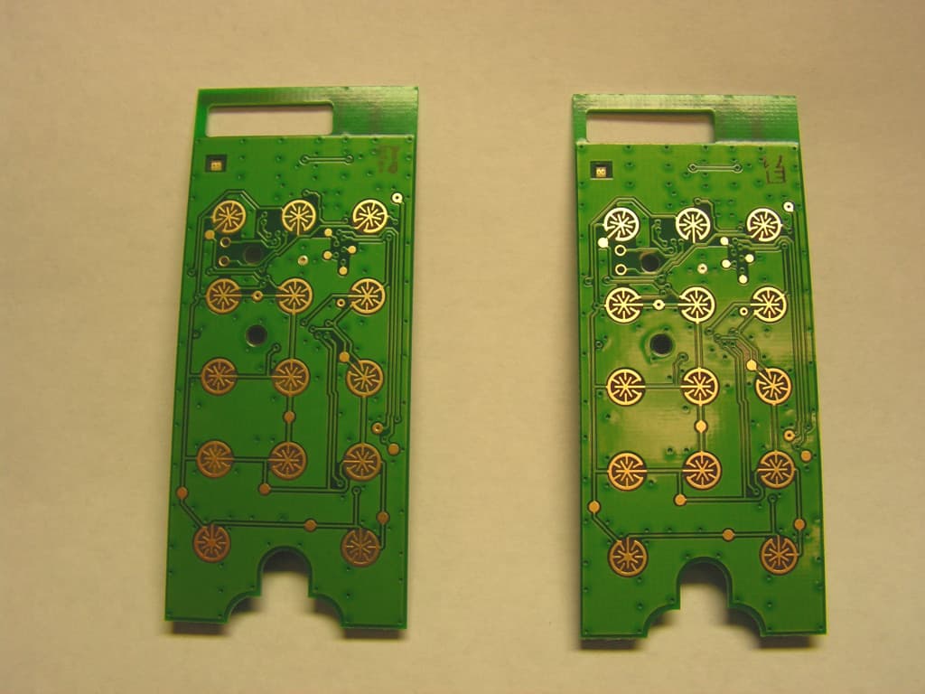
FBRE240D
Jan 10, 2013Low Power RF Module
Equipment Class
DXT - Part 15 Low Power Transceiver, Rx Verified