FBRIQK1000-9XXReply IQ Keypad Transceiver
Fleetwood Group Inc
Click to zoom
Application Details
- Equipment Class
- DXT - Part 15 Low Power Transceiver, Rx Verified
- Date of Grant
- Feb 11, 2003
- Application Purpose
- Original Equipment
- Date of Application
- Feb 11, 2003
- Equipment Note
- Reply IQ Keypad Transceiver
- Frequency Range
- 902.00000000 - 928.00000000
- Company
- Fleetwood Group Inc
- Country
- United States
Documents & Files
Document Text
Text extracted from the exhibit documents filed with the FCC. Open a document above to read the original.
Users Manual
Fleetwood Group Inc. FCC ID: FBRIQK1000-9XX Page 1 of 3 File Name: IQK1000_Manual User Manual Date: 1/30/2003 Reply IQ User Manual System Setup 1. Unpack the Reply IQB500 base unit and set it on a table or available surface in the vicinity of where the Reply IQK1000 Response Keypads will be used. 2. Plug the AC power module into the Reply IQ base DC input jack. 3. Plug the AC line cord from the power module into a 115 VAC power circuit. 4. Turn on the power switch of the Reply IQ base unit. 5. Plug either the RJ45 supplied cable into a network port, if Ethernet connection selected (or directly to a PC via a crossover cable), or a standard DB9 to DB9 RS232 cable into a COM port (usually Com1 or Com2) if serial connection selected. 6. Open the carrying case containing the response keypads and distribute them to the participants. 7. Turn on the computer and start the application software to control the base unit to poll for keypad responses. Each application software will have its own instructions for using the system. Operation 1. Instruct the participants on the usage of the response keypads and procedure for responding. 2. Ask a question and allow enough time (at least 10 seconds) for all participants to respond. 3. Observe the results on the screen and optionally save the results for later analysis if desired. 4. Proceed and repeat the process for the next question. 5. Continue until all questions are completed. 6. Analyze the responses for the period and run printouts if desired. System Shutdown 1. Turn off the power to the computer. 2. Turn off the power to the Reply IQ base unit. 3. Unplug the data cable from the computer and store it in its carrying case. 4. Unplug the AC line cord from the power module and store both in the carrying case. 5. Store the Reply IQ in its carrying case. 6. Collect the keypads and return them to their carrying case. 7. The system is now ready for transporting. Fleetwood Group Inc. FCC ID: FBRIQK1000-9XX Page 2 of 3 File Name: IQK1000_Manual User Manual Date: 1/30/2003 Reply IQ Keypad Operation The reply IQ keypad has 5 basic modes of operation: Single-Digit Entry, Multi-Digit Entry, Moment to Moment Entry, Speed Scoring, and the Options menu. From a power-off state, simply press any key to turn the keypad power on. The REPLY IQ Logo along with the keypad’s address and channel will be displayed briefly and then the keypad will enter normal operation in the mode most recently used. Single Digit Entry Mode In this mode, only one key press can be sent at a time. Simply press one of the numeric keys (0-9), and the number will be displayed in the center of the screen. The key shown on the screen will be sent to the base during the next polling interval. When the number clears from the screen, the base has successfully received the data. Multi Digit Entry Mode In Multi Digit mode, the user can send a response up to 16 characters. When the base is polling, data is sent from the keypad every time a new key is pressed. There is a maximum of 16 characters that can be sent. If the SEND key is pressed when 15 characters or less have been entered, the display will get “grayed” out and all further keypresses will be locked out except “C” and “Í“. When the base confirms that it got the data, the entry will be cleared, and data entry will begin again. Moment to Moment Entry Mode Moment to Moment mode allows the user to record their opinion of a certain event in the form of Very bad, bad, indifferent, good, or excellent”. In this mode a “ -- - 0 + ++” appears just above the 5 softkeys. Now press the key that corresponds to the desired opinion, and the display will be highlighted above the softkey to indicate a keypress happened. Information on when the key was pressed, and what value was entered gets stored in a buffer and sent to the base on the next polling interval. The keypad is able to store up to 128 different keypresses without ever hearing a polling command from the base station. However, since opinion based data can be entered quickly, measures must be taken to prevent this 128 entry buffer from filling up completely. The base can set the keypad to several different “resolution” settings to prevent too much data from being stored. If multiple keys are pressed during the set resolution time, the keypresses are averaged into one response. Using a ¼ second resolution will provide the greatest accuracy, but also generates the most data from a keypad. This should only be used with small groups of keypads. Resolutions of up to 10 seconds are reserved for very large numbers of keypads, where the time between polling messages is longer. Speed Scoring Mode Speed scoring mode operates similar to multi digit mode with the exception of a time- stamped response. The group being polled will attempt to answer a question at the same time. Based on the time-stamped responses from each keypad, it is possible to determine which keypad was pressed first down to the nearest 1/20 second. Speed Scoring is set up by the base station. Unlike Multi Digit mode, the maximum number of characters is selectable from 1-16. There is also the option of whether to Fleetwood Group Inc. FCC ID: FBRIQK1000-9XX Page 3 of 3 File Name: IQK1000_Manual User Manual Date: 1/30/2003 record the time stamp on either the last key pressed or time stamp on the SEND key only. Options Menu To access the Reply IQ keypad configuration menu, press “Í” and “1” at the same time when the keypad is any of the modes listed above. The following menu will appear: ___________________________ |OPTIONS | | | | ________ _________ | ||1:Single||5:Address|| ||2:Multi ||6:Channel|| ||3:Moment||7:POWER || ||4:Speed ||Send:Exit|| | -------- --------- | |_____________________| The menu keys perform the following functions: KEYS 1-4: Manually switch the keypads into Single, Multi, Speedscoring, or Moment to moment entry modes. Any special options such as maximum number of characters will have to be set by the base. KEY 5: Set th…
Text truncated - open the document above for the full version.
Cover Letter(s)
AHD EMC Lab, 92723 M152, Dowagiac, MI 49047, (616) 424-7014 302416.DOC Cover / Confidentiality Request Letter: Page 1 of 2 NVLAP ACCREDITED NARTE Certified Engineer Professional Engineer Federal Communications Commission Equipment Approval Services, P.O. Box 358315 Pittsburgh, PA 15251-5315 Attention : Authorization & Evaluation Division Re: Application for Certification of Fleetwood Group Inc. Transceiver under 47CFR 15.249. FCC ID: FBRIQK1000-9XX Gentlemen: On behalf of the applicant, Fleetwood Group Inc., please find attached the submittal materials for certification of the “Reply IQ Keypad Transceiver”, Model IQK1000. This product, a part of Fleetwood Group’s audience interaction technology, operates within the 902-928MHz frequency band. The complete List of the Exhibits in this submittal package appears on Page 2 of this cover letter. Fleetwood Group Inc. has invested considerable resources into developing this product series. Pursuant to 47CRF 0.459, the Fleetwood Group requests that the Circuit Block Diagrams, Theory/Description of Operation, and Schematics be held confidential. A formal letter addressing this request is reproduced in the file: IQK1000_Request.pdf. The Federal Communications Commission will be notified, in writing, of any changes in the software/programming of the device that could affect the device’s RF characteristics. Your prompt consideration of this application for product certification will be greatly appreciated. Should you have any questions regarding the content of this report, kindly contact me. Sincerely, Ted Chaffee, Technical Lab Manager Narte Certified Engineer, #EMC-002025-NE tel/fax: 616. 424.7014 email: [email protected], or [email protected] Test report #0200585F FCC 15.249 for IQK1000 FCC ID: FBRIQK1000-9XX Tested January 27, 2003 AHD EMC Lab, 92723 M152, Dowagiac, MI 49047, (616) 424-7014 302416.DOC Cover / Confidentiality Request Letter: Page 2 of 2 Table of Contents Cover Letter / Table of Contents Total Pages 2 EXHIBIT A: ID Label / Location [2.925,2.926,2.1033(b2,7),15.19(a3)] IQK1000_Label.pdf Total Pages 1 EXHIBIT B: Description of Product [2.1033(b6)] Circuit Block Diagram [2.1033(b5)] Description of Operation [2.1033(b4)] IQK1000_TechDesc.pdf Total Pages 7 Schematic [2.1033(b5)] Keypad – 2 pages, Xemics Module – 1 page IQK1000_Schem.pdf Total Pages 3 EXHIBIT C: Product photos [2.1033(b7)] Exterior views – 2 photos; Interior views – 2 photos; Printed Circuit Board views – 2 photos IQK1000_Photos.pdf Total Pages 2 EXHIBIT D: User’s Manual IQK1000_Manual.pdf Total Pages 3 EXHIBIT E: Setup photos [2.1033(b8)] Five photos Total Pages 6 EXE_pretest.jpg, EXE_side.jpg, EXE_end.jpg, EXE_flat.jpg, EXE_RadHi.jpg Report of Measurements [2.1033(b6)] Total Pages 20 Table of Contents Page 2 Manufacturer/Applicant [2.1033(b1)] Page 4 Measurement/Test Facility & Equipment Page 4 Configuration/Setup [2.1033(b8)] Page 5 Test Standards / Methods Used [2.1033(b6)] Page 7 Test Methodology [2.1033(b6)] Page 8 Test Data [2.1033(b6)] Summary of Results Page 6 Bandedge Page 12 Radiated Field Strength [15.249(b)] Page 14 Misc. EXHIBIT: RF Exposure Information [2.1093(c)] Total Pages 1
External Photos
Reply® Model IQK1000 Photos Fleetwood Group Inc. FCC ID: FBRIQK1000-9XX Page 1 of 2 File Name: IQK1000_Photos Date: 01/29/03 Keypad Case External Top and Bottom Keypad Case Inside Reply® Model IQK1000 Photos Fleetwood Group Inc. FCC ID: FBRIQK1000-9XX Page 2 of 2 File Name: IQK1000_Photos Date: 01/29/03 Keypad Circuit Board
ID Label/Location Info
Fleetwood Group Inc. FCC ID: FBRIQK1000-9XX FCC Label Page 1 of 1 File Name: IQK1000_Label.doc Date: 2/6/2003 Location of label on underside of keypad Label Details: Black text on Metalised Polyester Stock 1.47” X 0.97” Label Corner Radius .12”
Internal Photos
Reply® Model IQK1000 Photos Fleetwood Group Inc. FCC ID: FBRIQK1000-9XX Page 1 of 2 File Name: IQK1000_Photos Date: 01/29/03 Keypad Case External Top and Bottom Keypad Case Inside Reply® Model IQK1000 Photos Fleetwood Group Inc. FCC ID: FBRIQK1000-9XX Page 2 of 2 File Name: IQK1000_Photos Date: 01/29/03 Keypad Circuit Board
RF Exposure Info
Test report #0200585KF FCC 15.249 for IQK1000 FCC ID: FBRIQK1000-9XX Tested January 27, 2003 AHD EMC Lab, 92723 M152, Dowagiac, MI 49047, (616) 424-7014 302415.DOC Misc. EXHIBIT: Page 1 of 1 MISC. EXHIBIT: RF EXPOSURE INFORMATION [2.1093(C)] The manufacturer and applicant: FLEETWOOD GROUP Inc. P.O. Box 1259 Holland, Michigan 49422-1259 Product: Reply IQ Keypad Transceiver Model: IQK1000 Applicable Rules: 47CFR Part 15.249 Pursuant to 47CFR Part 1.1307(b), 47CFR Part 2.1091(c), and 47CFR Part 2.1093(c) this transmitting device, compliant to 47CFR Part 15.249, is categorically excluded from evaluation regarding the Maximum Permissible Exposure of RF energy.
Test Report
Test report #0200585KF FCC 15.249 for IQK1000 FCC ID: FBRIQK1000-9XX Tested January 20, 2003 AHD EMC Lab, 92723 M152, Dowagiac, MI 49047, (616) 424-7014 302419.DOC EXHIBIT E: Page 1 of 20 EXHIBIT E: REPORT OF MEASUREMENTS [2.1033(B6)] Test Report for FCC ID: FBRIQK1000-9XX FCC Part 2.1031, Part 15 Subpart C(15.249) Report #0200585KF Issued 02/07/03 TRANSCEIVER MODEL IQK1000 Prepared for: Mr. Harry Derks Fleetwood Group Inc. P.O. Box 1259 Holland, MI 49422-1259 Test Date(s): December 18,19,20, 2002, January 10,17,27, 2003 data recorded by witnessed by Ted Chaffee, NCE Dave Ramon Harry Derks This report prepared by: Ted Chaffee, NCE Technical Manager/Test Engineer, AHD Test report #0200585KF FCC 15.249 for IQK1000 FCC ID: FBRIQK1000-9XX Tested January 27, 2003 AHD EMC Lab, 92723 M152, Dowagiac, MI 49047, (616) 424-7014 302419.DOC EXHIBIT E: Page 2 of 20 TABLE OF CONTENTS EXHIBIT E: Report of Measurements [2.1033(b6)] .....................................................................................1 TABLE OF CONTENTS.........................................................................................................................2 Statements Concerning this Report.......................................................................................................3 Manufacturer/Applicant [2.1033(b1)] ....................................................................................................4 Measurement/Test Site Facility & Equipment........................................................................................4 Test Site [2.948, 2.1033(b6)] ......................................................................................................4 Measurement Equipment Used [2.947(d), 15.31(b)] ....................................................................4 Tested Configuration /Setup: [2.1033(b8)] ............................................................................................5 Support Equipment & Cabling .......................................................................................................5 Setup Diagram ...............................................................................................................................5 Summary of Results: .............................................................................................................................6 Changes made to achieve compliance..........................................................................................7 Standards Applied to Test: [2.1033(b6)]................................................................................................8 Test Methodology: [2.1033(b6)].............................................................................................................8 FORMULAS AND SAMPLE CALCULATIONS: ...........................................................................10 Test Data [2.1033(b6)].........................................................................................................................11 Modulation Characteristics ..........................................................................................................11 Band Edges [15.249(d)] ...............................................................................................................12 Radiated Field Strength Measurements: [15.209, 15.249(a,d)] .................................................14 Spurious Emissions: [15.249d] ............................................................................................14 Field Strength Measurements of Fundamental & LO: [15.249(a), 15.209]..........................16 Field Strength Measurements of Fundamental & LO Harmonics: [15.249(d)] ....................17 Test report #0200585KF FCC 15.249 for IQK1000 FCC ID: FBRIQK1000-9XX Tested January 27, 2003 AHD EMC Lab, 92723 M152, Dowagiac, MI 49047, (616) 424-7014 302419.DOC EXHIBIT E: Page 3 of 20 Statements Concerning this Report NVLAP Accreditation: NVLAP Lab Code 200129-0 The scope of AHD accreditation is the conducted emissions, radiated emissions test methods of: IEC/CISPR 22: Limits and methods measurement of radio disturbance characteristics of information technology equipment. FCC Method – 47 CFT Part 15 – Digital Devices. AS/NZS 3548: Electromagnetic Interference – Limits and Methods of Measurement of Information Technology Equipment. IEC61000-4-2 and Amend.1: ElectroStatic Discharge Immunity Test Data: This test report contains data covered by the NVLAP accreditation. Subcontracted Testing: This report contains data recorded at the University of Michigan Radiation Laboratory. The University of Michigan test facility is located at 8501 Beck Road, Belleville, Michigan 48111. This test facility has been fully described and accepted by the FCC and Industry Canada. This facility was utilized to measure emissions occurring at frequencies greater than 6GHz. Test Traceability: The calibration of all measuring and test equipment and the measured data using this equipment are traceable to the National Institute for Standards and Technology (NIST). Limitations on results: The test results contained in this report relate only to the Item(s) tested. Any electrical or mechanical modification made to the test item subsequent to the test date shall invalidate the data presented in this report. Any electrical or mechanical modification made to the test item subsequent to this test date shall require an evaluation to verify continued compliance. Limitations on copying: This report shall not be reproduced, except in full, without the written approval of AHD. Limitations of the report: This report shall not be used to claim product endorsement by NVLAP, FCC, or any agency of the US Government. Statement of Test Results Uncertainty: Following the guidelines of NAMAS publication NIS81 and NIST Technical Note 1297, the Measurement Uncertainty at a 95% confidence level is determined to be: ± 1.4 dB Test report #0200585KF FCC 15.249 for IQK1000 F…
Text truncated - open the document above for the full version.
Test Setup Photos
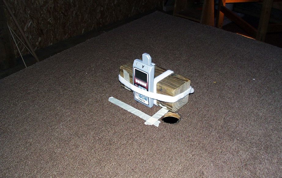
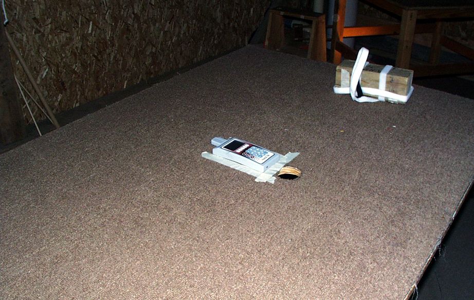
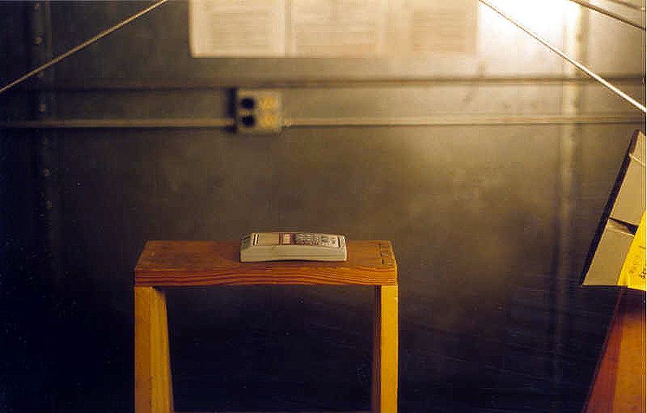
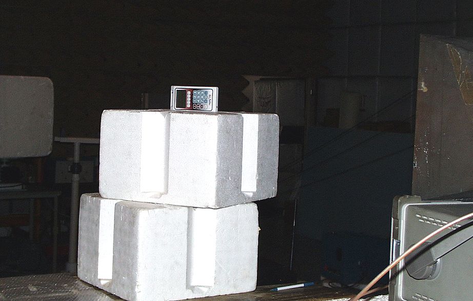
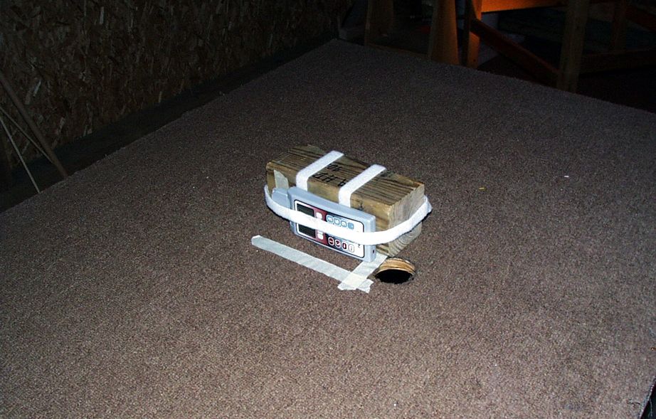
Test report #0200585KF FCC 15.249 for IQK1000 FCC ID: FBRIQK1000-9XX Tested January 27, 2003 AHD EMC Lab, 92723 M152, Dowagiac, MI 49047, (616) 424-7014 302425.DOC EXHIBIT E: Page 1 of 6 EXHIBIT E: SETUP PHOTOGRAPHS [ANSI C63.4, 2.1033(B8)] Setup Pictures EUT pretest for emission spectrum Refer to picture file “EXE_pretest.jpg” EUT in “SIDE” position Refer to picture file “EXE_side.jpg” EUT in “END” position Refer to picture file “EXE_end.jpg” EUT in “FLAT” position Refer to picture file “EXE_flat.jpg” EUT at location for measurements >6GHz Refer to picture file “EXE_RadHi.jpg”
Contact Information
Applicant
Brian Harvey(VP Engineering, Electronics)
Test Firm
AHD EMC LaboratoryGordon Helm
Technical Specifications
| # | Rule Parts | Frequency Range | Power Output |
|---|---|---|---|
| 1 | 15C | 902 MHz - 928 MHz | - |
Other Applications from Fleetwood Group Inc
FBR5900
Mar 06, 2026Low Power BLE Transceiver
Equipment Class
DTS - Digital Transmission SystemFBR5820
Dec 02, 2025Low Power BLE Transceiver
Equipment Class
DTS - Digital Transmission SystemFBR-HR350C-1
Apr 04, 2024Collar Mounted Transceiver
Equipment Class
TNT - Licensed Non-Broadcast Transmitter Worn on BodyFBR-HR350R-1
Apr 04, 2024Handheld Remote Transceiver
Equipment Class
TNT - Licensed Non-Broadcast Transmitter Worn on Body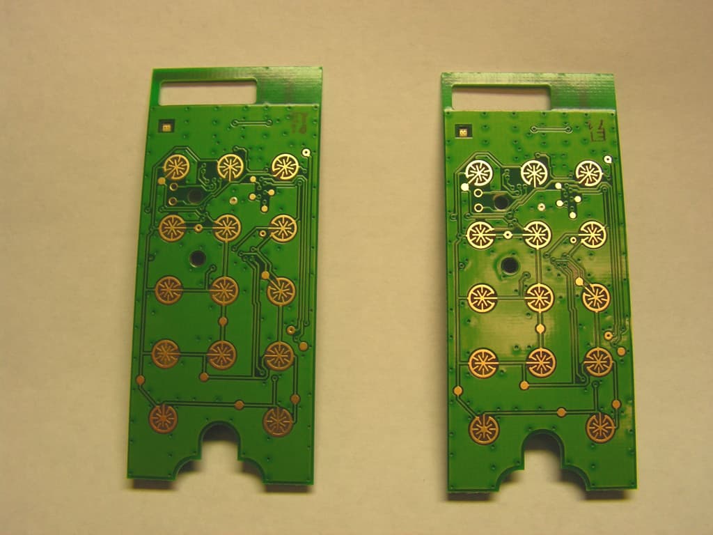
FBRE240D
Jan 10, 2013Low Power RF Module
Equipment Class
DXT - Part 15 Low Power Transceiver, Rx Verified