FBRV240BLow Power RF and IR Module
Fleetwood Group Inc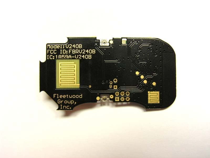
Click to zoom
Application Details
- Equipment Class
- DXT - Part 15 Low Power Transceiver, Rx Verified
- Date of Grant
- Dec 27, 2010
- Application Purpose
- Original Equipment
- Date of Application
- Dec 26, 2010
- Equipment Note
- Low Power RF and IR Module
- Frequency Range
- 2401.00000000 - 2475.00000000
- Company
- Fleetwood Group Inc
- Country
- United States
Documents & Files
Document Text
Text extracted from the exhibit documents filed with the FCC. Open a document above to read the original.
Users Manual
Rhein Tech Laboratories, Inc. Client: Fleetwood Group, Inc. 360 Herndon Parkway Model: V240B Suite 1400 Standards: FCC 15.249/IC RSS-210 Herndon, VA 20170 http://www.rheintech.com FCC/IC ID: FBRV240B/1859A-V240B Report #: 2010232 Page 29 of 39 Appendix L: Manual Please refer to the following pages. USER MANUAL VL4B Module ii Copyright 2007 Fleetwood Group, Inc., Electronics Division. All rights reserved. Licensed software products are owned by Fleetwood Group, Inc. or its suppliers and are protected by United States copyright laws and international treaty provisions. Fleetwood Group, Inc. products are covered by U.S. and foreign patents, issued and pending. Information in this publication supersedes that in all previously published material. Specifications and pricing are subject to change without notice. Printed in the U.S.A. Fleetwood Group, Inc. Electronics Division 11832 James St. Holland, Michigan 49424 www.fleetwoodgroup.com Sales: 1-800-257-6390 Technical Service: 1-888-GO-REPLY (467-3759) Reply ® is a registered trademark of Fleetwood Group, Inc. Other trademarks contained herein are the property of their respective holders. Revision History: Rev Date Description A 12/8/2010 Original iii Table of Contents 1.0 V240B MODULE .................................................................................................................................................. 4 1.1 DESCRIPTION ....................................................................................................................................................... 4 1.2 BATTERY REPLACEMENT ..................................................................................................................................... 4 1.3 FCC AND IC ......................................................................................................................................................... 4 1.4 STANDARDS AND GUIDELINES ............................................................................................................................. 4 1.5 FCC/IC COMPLIANCE .......................................................................................................................................... 5 4 1.0 VL4B Module 1.1 Description The V240B is a low power real time locating system badge. The V240B module is used to identify the location of an individual or asset location. It communicates at 2.4GHz, to a ceiling sensor module or a link module, and uses IR emitters that communicate with the ceiling sensor to determine its location. The overall operation of the V240B module is controlled by a microcontroller. This microcontroller is powered from approximately 3V and uses a 16 MHz reference. The microcontroller handles control of the RF and IR communications, indicator LEDs, external I/O, and keypad inputs. RF communications use a 2.4 GHz transceiver. The transceiver chip uses a 16 MHz reference oscillator that is shared with the microcontroller for TX/RX and is also powered by 3V. The transceiver uses an integral antenna on the PCB. 1.2 Battery Replacement The V240B is powered from a 3V battery. The battery is replaceable. To replace battery, open the case, remove the old battery, and replace with a new battery noting its polarity. The negative side of the battery should be facing the PCB. 1.3 FCC and IC V240B Module Responsible Party Pertaining to the Declaration of Conformity Fleetwood Group, Inc. 11832 James Street Holland, MI 49424 Attn: Product Service Coordinator Phone: 888-467-3759 1.4 Standards and Guidelines This device complies with the following USA/Canada Regulations: The USA Federal Communications Commission (FCC) Rules and Regulations Industry Canada Rules and Regulations This device complies with the following national and international standards: FCC Part 15B, 15.249 (10-01-09) IC RSS-210 Issue 7 5 1.5 FCC/IC Compliance This device complies with Part 15 of the FCC Rules and RSS-210 of the Industry Canada Rules. Operation is subject to the following two conditions: (1) this device may not cause interference and (2) this device must accept any interference, including interference that may cause undesired operation of the device. The user is cautioned that changes or modifications to the device that are not approved by the manufacturer could void the user’s authority to operate the device.
Cover Letter(s)
Rhein Tech Laboratories, Inc. Client: Fleetwood Group, Inc. 360 Herndon Parkway Model: V240B Suite 1400 Standards: FCC 15.249/IC RSS-210 Herndon, VA 20170 http://www.rheintech.com FCC/IC ID: FBRV240B/1859A-V240B Report #: 2010232 Page 18 of 39 Appendix B: Agency Authorization Letter Please refer to the following page.
Cover Letter(s)
Rhein Tech Laboratories, Inc. Client: Fleetwood Group, Inc. 360 Herndon Parkway Model: V240B Suite 1400 Standards: FCC 15.249/IC RSS-210 Herndon, VA 20170 http://www.rheintech.com FCC/IC ID: FBRV240B/1859A-V240B Report #: 2010232 Page 19 of 39 Appendix C: FCC Confidentiality Request Letter Please refer to the following page.
Cover Letter(s)
Rhein Tech Laboratories, Inc. Client: Fleetwood Group, Inc. 360 Herndon Parkway Model: V240B Suite 1400 Standards: FCC 15.249/IC RSS-210 Herndon, VA 20170 http://www.rheintech.com FCC/IC ID: FBRV240B/1859A-V240B Report #: 2010232 Page 20 of 39 Appendix D: DA 00-1407 FCC Part 15 Unlicensed Modular Transmitter Approval Please refer to the following pages. Federal Communications Commission 12/9/2010 Equipment Authorization Branch 7435 Oakland Mills Road Columbia, MD 21046 To Whom It May Concern: In regards to RF Module, model V240B. This letter addresses each of the points numbered 1-8 on page 2 of the DA00-1407 Part 15 Unlicensed Limited Modular Approval. In response to: “ 1. The modular transmitter must have its own RF shielding. This is intended to ensure that the module does not have to rely upon the shielding provided by the device into which it is installed in order for all modular transmitter emissions to comply with Part 15 limits. It is also intended to prevent coupling between the RF circuitry of the module and any wires or circuits in the device into which the module is installed. Such coupling may result in non-compliant operation.” The module uses microstrip shielding, ground plane, and ground plane flooding to effectively control emissions. Spurious emissions have been checked and shown to be compliant. For final products that contain the certified device and do not use a typical enclosure, spurious emissions testing is required to confirm compliance. In response to: “2. The modular transmitter must have buffered modulation/data inputs (if such inputs are provided) to ensure that the module will comply with Part 15 requirements under conditions of excessive data rates or over-modulation.” All modulation data inputs are internal to the transceiver chip. Filtering has been provided on all external I/O interfaces. In response to: “3. The modular transmitter must have its own power supply regulation. This is intended to ensure that the module will comply with Part 15 requirements regardless of the design of the power supplying circuitry in the device into which the module is installed.” The module is battery powered, and the transmitter uses internal constant current sources to regulate the affects of battery voltage. The grantee will maintain full control of all end products, and will ensure that they are solely battery operated. Fleetwood Group, Inc. Mail: P.O. Box 1259 Holland, MI 49422-1259 - Ship: 11832 James Street Holland, MI 49424 Phone: (616) 369-1142 - Toll Free (800) 257-6390 - Corporate Fax: (616) 820-8300 In response to: “4. The modular transmitter must comply with the antenna requirements of Section 15.203 and 15.204(c). The antenna must either be permanently attached or employ a “unique” antenna coupler (at all connections between the module and the antenna, including the cable). Any antenna used with the module must be approved with the module, either at the time of initial authorization or through a Class II permissive change. The “professional installation” provision of Section 15.203 may not be applied to modules.” The module uses an internal etched PCB antenna. In response to: “5. The modular transmitter must be tested in a stand-alone configuration, i.e., the module must not be inside another device during testing. This is intended to demonstrate that the module is capable of complying with Part 15 emission limits regardless of the device into which it is eventually installed. Unless the transmitter module will be battery powered, it must comply with the AC line conducted requirements found in Section 15.207. AC or DC power lines and data input/output lines connected to the module must not contain ferrites, unless they will be marketed with the module (see Section 15.27(a)). The length of these lines shall be length typical of actual use or, if that length is unknown, at least 10 centimeters to insure that there is no coupling between the case of the module and supporting equipment. Any accessories, peripherals, or support equipment connected to the module during testing shall be unmodified or commercially available (see Section 15.31(i)).” The module is battery powered and shall be tested in a stand-alone configuration. In response to: “6. The modular transmitter must be labeled with its own FCC ID number, and, if the FCC ID is not visible when the module is installed inside another device, then the outside of the device into which the module is installed must also display a label referring to the enclosed module. This exterior label can use wording such as the following: “Contains Transmitter Module FCC ID: XYZMODEL1” or “Contains FCC ID: XYZMODEL1.” Any similar wording that expresses the same meaning may be used. The Grantee may either provide such a label, an example of which must be included in the application for equipment authorization, or, must provide adequate instructions along with the module which explain this requirement. In the latter case, a copy of these instructions must be included in the application for equipment authorization.” The module and final assembly shall comply with the stated labeling. Fleetwood Group, Inc. Mail: P.O. Box 1259 Holland, MI 49422-1259 - Ship: 11832 James Street Holland, MI 49424 Phone: (616) 369-1142 - Toll Free (800) 257-6390 - Corporate Fax: (616) 820-8300 In response to: “7. The modular transmitter must comply with any specific rule or operating requirements applicable to the transmitter and the manufacturer must provide adequate instructions along with the module to explain any such requirements. A copy of these instructions must be included in the application for equipment authorization. For example, there are very strict operational and timing requirements that must be met before a transmitter is authorized for operation under Section 15.231. For instance, data transmission is prohibited, except for operation under Section 15.231(e), in which case there are separate field strength level and timing requirements…
Text truncated - open the document above for the full version.
External Photos
Rhein Tech Laboratories, Inc. Client: Fleetwood Group, Inc. 360 Herndon Parkway Model: V240B Suite 1400 Standards: FCC 15.249/IC RSS-210 Herndon, VA 20170 http://www.rheintech.com FCC/IC ID: FBRV240B/1859A-V240B Report #: 2010232 Page 32 of 39 Appendix N: External Photographs Photograph 5: Top View Rhein Tech Laboratories, Inc. Client: Fleetwood Group, Inc. 360 Herndon Parkway Model: V240B Suite 1400 Standards: FCC 15.249/IC RSS-210 Herndon, VA 20170 http://www.rheintech.com FCC/IC ID: FBRV240B/1859A-V240B Report #: 2010232 Page 33 of 39 Photograph 6: Bottom View Rhein Tech Laboratories, Inc. Client: Fleetwood Group, Inc. 360 Herndon Parkway Model: V240B Suite 1400 Standards: FCC 15.249/IC RSS-210 Herndon, VA 20170 http://www.rheintech.com FCC/IC ID: FBRV240B/1859A-V240B Report #: 2010232 Page 34 of 39 Photograph 7: Side 1 View Rhein Tech Laboratories, Inc. Client: Fleetwood Group, Inc. 360 Herndon Parkway Model: V240B Suite 1400 Standards: FCC 15.249/IC RSS-210 Herndon, VA 20170 http://www.rheintech.com FCC/IC ID: FBRV240B/1859A-V240B Report #: 2010232 Page 35 of 39 Photograph 8: Side 2 View
ID Label/Location Info
Rhein Tech Laboratories, Inc. Client: Fleetwood Group, Inc. 360 Herndon Parkway Model: V240B Suite 1400 Standards: FCC 15.249/IC RSS-210 Herndon, VA 20170 http://www.rheintech.com FCC/IC ID: FBRV240B/1859A-V240B Report #: 2010232 Page 24 of 39 Appendix H: Label and Label Location Photograph 1: ID Label on EUT Rhein Tech Laboratories, Inc. Client: Fleetwood Group, Inc. 360 Herndon Parkway Model: V240B Suite 1400 Standards: FCC 15.249/IC RSS-210 Herndon, VA 20170 http://www.rheintech.com FCC/IC ID: FBRV240B/1859A-V240B Report #: 2010232 Page 25 of 39 Photograph 2: “Contains FCC ID...” Label on Sample Host
Internal Photos
Rhein Tech Laboratories, Inc. Client: Fleetwood Group, Inc. 360 Herndon Parkway Model: V240B Suite 1400 Standards: FCC 15.249/IC RSS-210 Herndon, VA 20170 http://www.rheintech.com FCC/IC ID: FBRV240B/1859A-V240B Report #: 2010232 Page 36 of 39 Appendix O: Internal Photographs Photograph 9: Top View Rhein Tech Laboratories, Inc. Client: Fleetwood Group, Inc. 360 Herndon Parkway Model: V240B Suite 1400 Standards: FCC 15.249/IC RSS-210 Herndon, VA 20170 http://www.rheintech.com FCC/IC ID: FBRV240B/1859A-V240B Report #: 2010232 Page 37 of 39 Photograph 10: Bottom View Rhein Tech Laboratories, Inc. Client: Fleetwood Group, Inc. 360 Herndon Parkway Model: V240B Suite 1400 Standards: FCC 15.249/IC RSS-210 Herndon, VA 20170 http://www.rheintech.com FCC/IC ID: FBRV240B/1859A-V240B Report #: 2010232 Page 38 of 39 Photograph 11: Side 1 View Rhein Tech Laboratories, Inc. Client: Fleetwood Group, Inc. 360 Herndon Parkway Model: V240B Suite 1400 Standards: FCC 15.249/IC RSS-210 Herndon, VA 20170 http://www.rheintech.com FCC/IC ID: FBRV240B/1859A-V240B Report #: 2010232 Page 39 of 39 Photograph 12: Side 2 View
Test Report
Engineering and Testing for EMC and Safety Compliance 360 Herndon Parkway, Suite 1400 Herndon, VA 20170 Tel: 703-689-0368 Fax: 703-689-2056 Limited Modular Approval Certification Application Report FCC Part 15.249 & Industry Canada RSS-210 Test Lab: Rhein Tech Laboratories, Inc. Tel: 703-689-0368 360 Herndon Parkway Fax: 703-689-2056 Suite 1400 www.rheintech.com Herndon, VA 20170 E-Mail: [email protected] Applicant: Fleetwood Group, Inc. Tel: 616-820-8271 11832 James Street Fax: 616-820-8300 Holland, MI 49424 Contact: Will Buehler FCC ID/ IC: FBRV240B/ 1859A-V240B Test Report Date: December 8, 2010 Platform: N/A RTL Work Order #: 2010232 Model: V240B RTL Quote #: QRTL10-183 American National Standard Institute: ANSI C63.4-2003: Methods of Measurement of Radio-Noise Emissions from Low-Voltage Electrical and Electronic Equipment in the Range of 9 kHz to 40 GHz FCC Classification: DXT – Part 15 Low Power Transceiver FCC Rule Part(s)/Guidance: 15.249: Operation within the bands 902-928 MHz, 2400-2483.5 MHz, 5725- 5875 MHZ, and 24.0-24.25 GHz, October 1, 2009 Industry Canada: RSS-210 Issue 7: Low Power License-Exempt Communications Devices Digital Interface Information: Digital Interface was found to be compliant Frequency Range (MHz) Output Power (W) Frequency Tolerance Emission Designator 2401 – 2475 N/A N/A 733KFXD I, the undersigned, hereby declare that the equipment tested and referenced in this report conforms to the identified standard(s) as described in this test report. No modifications were made to the equipment during testing in order to achieve compliance with these standards. Furthermore, there was no deviation from, additions to, or exclusions from, the applicable parts of FCC Part 2, FCC Part 15 and ANSI C63.4. Signature: Date: December 8, 2010 Typed/Printed Name: Desmond A. Fraser Position: President This report may not be reproduced, except in full, without the written approval of Rhein Tech Laboratories, Inc. and Fleetwood Group, Inc. The test results relate only to the item(s) tested. These tests are accredited and meet the requirements of ISO/IEC 17025 as verified by ANSI-ASQ National Accreditation Board/ACLASS. Refer to certificate and scope of accreditation AT-1445. Rhein Tech Laboratories, Inc. Client: Fleetwood Group, Inc. 360 Herndon Parkway Model: V240B Suite 1400 Standards: FCC 15.249/IC RSS-210 Herndon, VA 20170 http://www.rheintech.com FCC/IC ID: FBRV240B/1859A-V240B Report #: 2010232 Page 2 of 39 Table of Contents 1 General Information ...................................................................................................................................................... 5 1.1 Scope ....................................................................................................................................................................... 5 1.2 Description of EUT ................................................................................................................................................... 5 1.3 Test Facility .............................................................................................................................................................. 5 1.4 Related Submittal(s)/Grant(s) .................................................................................................................................. 5 1.5 Modifications ............................................................................................................................................................ 5 2 Test Information ............................................................................................................................................................ 6 2.1 Description of Test Modes ....................................................................................................................................... 6 2.2 Exercising the EUT .................................................................................................................................................. 6 2.3 Test Result Summary .............................................................................................................................................. 6 2.4 Test System Details ................................................................................................................................................. 7 2.5 Configuration of Tested System ............................................................................................................................... 7 3 Duty Cycle Calculation - FCC §15.35(c), RSS-Gen §4.3 .............................................................................................. 8 4 Radiated Emissions – FCC §15.209, §15.249(a); RSS-210 §6.2.1 .............................................................................. 8 4.1 Limits of Radiated Emissions Measurement ............................................................................................................ 8 4.2 Radiated Emissions Measurement Test Procedure ................................................................................................. 8 4.3 Radiated Emissions Test Results .......................................................................................................................... 10 4.4 Radiated Emissions Harmonics/Spurious Test Data .............................................................................................. 10 4.5 Radiated Emissions Digital Test Data .................................................................................................................... 11 5 AC Conducted Emissions - FCC §15.207; RSS-Gen §7.2.2: Conducted Limits; ANSI C63.4-2003 Section 7 .......... 12 6 20 dB Bandwidth – IC RSS-Gen ................................................................................................................................. 12 6.1 20 dB Bandwidth Test Procedure .................................................…
Text truncated - open the document above for the full version.
Test Setup Photos
Rhein Tech Laboratories, Inc. Client: Fleetwood Group, Inc. 360 Herndon Parkway Model: V240B Suite 1400 Standards: FCC 15.249/IC RSS-210 Herndon, VA 20170 http://www.rheintech.com FCC/IC ID: FBRV240B/1859A-V240B Report #: 2010232 Page 30 of 39 Appendix M: Test Photographs Photograph 3: Radiated Testing – Front View Rhein Tech Laboratories, Inc. Client: Fleetwood Group, Inc. 360 Herndon Parkway Model: V240B Suite 1400 Standards: FCC 15.249/IC RSS-210 Herndon, VA 20170 http://www.rheintech.com FCC/IC ID: FBRV240B/1859A-V240B Report #: 2010232 Page 31 of 39 Photograph 4: Radiated Testing – Back View
Contact Information
Applicant
Brian Harvey(VP Engineering, Electronics)
Technical Contact
Rhein Tech LabsRick McMurray
[email protected]703-689-0459
360 Herndon Parkway Suit 1400 · Herndon, Virginia · United States
Test Firm
Rhein Tech Laboratories, Inc.Richard McMurray
Technical Specifications
| # | Rule Parts | Frequency Range | Power Output |
|---|---|---|---|
| 1 | 15C | 2.40 GHz - 2.48 GHz | - |
Other Applications from Fleetwood Group Inc
FBR5900
Mar 06, 2026Low Power BLE Transceiver
Equipment Class
DTS - Digital Transmission SystemFBR5820
Dec 02, 2025Low Power BLE Transceiver
Equipment Class
DTS - Digital Transmission SystemFBR-HR350C-1
Apr 04, 2024Collar Mounted Transceiver
Equipment Class
TNT - Licensed Non-Broadcast Transmitter Worn on BodyFBR-HR350R-1
Apr 04, 2024Handheld Remote Transceiver
Equipment Class
TNT - Licensed Non-Broadcast Transmitter Worn on Body
FBRE240D
Jan 10, 2013Low Power RF Module
Equipment Class
DXT - Part 15 Low Power Transceiver, Rx Verified