FNXCR-252900 MHz DSSS Cordless Telephone
Cherish Telecom Co Ltd
Click to zoom
Application Details
- Equipment Class
- DSS - Part 15 Spread Spectrum Transmitter
- Date of Grant
- Jul 20, 1999
- Application Purpose
- Original Equipment
- Date of Application
- Jun 06, 1999
- Equipment Note
- 900 MHz DSSS Cordless Telephone
- Frequency Range
- 903.60000000 - 926.40000000
- Company
- Cherish Telecom Co Ltd
- Country
- Taiwan
Documents & Files

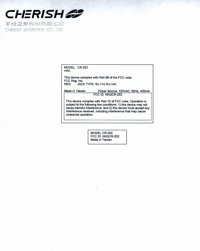
Document Text
Text extracted from the exhibit documents filed with the FCC. Open a document above to read the original.
Test Report
Intertek Testing Services APPLICATION FOR FCC CERTIFICATION GVC Corporation 900 MHz DSSS Cordless Telephone Model: CR-252 FCC ID: FNXCR-252 Job # J98033507 Number of Pages: 73 Date of Report: May 15, 1999 This report shall not be reproduced except in full, without written approval of Intertek Testing Services. This report must not be used to claim product endorsement by NVLAP or any agency of the U.S. Government. The results contained in this report were derived from measurements performed on the identified test samples. Any implied performance of other samples on this report is dependent on the representative of the samples tested. k:\..\fcc\15247ds.cerFCC Part 15 DSSS Cert, Ver 8/98 Intertek Testing Services 1365 Adams Court, Menlo Park, CA 94025 GVC Corporation, DSSS Digital Cordless PhoneDate of Test: 9/29/98 - 10/05/98, 4/20/99, & 4/23/99 FCC ID: FNXCR-252 Report # J98033507FCC Part 15.247 DSSS Certification ii Table of Contents 1.0Summary of Tests...............................................................1 2.0General Description..............................................................2 2.1Product Description........................................................2 2.2Related Submittal(s) Grants..................................................2 2.3Test Methodology..........................................................3 2.4Test Facility..............................................................3 3.0System Test Configuration ........................................................4 3.1Support Equipment.........................................................4 3.2Block Diagram of Test Setup.................................................4 3.3Justification..............................................................5 3.4Software Exercise Program..................................................5 3.5Mode of Operation During Test...............................................5 3.6Modifications Required for Compliance........................................5 3.7Additions, deviations and exclusions from standards..............................5 4.0Measurement Results ............................................................6 4.1Maximum Conducted Output Power at Antenna Terminals.........................6 4.2Minimum 6 dB RF Bandwidth..............................................14 4.3Maximum Power Density Reading...........................................20 4.4Out of Band Conducted Emissions...........................................33 4.5Out of Band Radiated Emissions.............................................33 4.6Transmitter Radiated Emissions in Restricted Bands.............................33 4.7AC Line Conducted Emission...............................................61 4.10Radiated Emissions from Digital Section of Transceiver (Transmitter), ..............64 4.11Radiated Emissions from Receiver Section of Transceiver (L.O. Radiation), ..........64 4.12Processing Gain Measurements..............................................73 4.13Transmitter Duty Cycle Calculation and Measurements...........................73 Intertek Testing Services 1365 Adams Court, Menlo Park, CA 94025 GVC Corporation, DSSS Digital Cordless PhoneDate of Test: 9/29/98 - 10/05/98, 4/20/99, & 4/23/99 FCC ID: FNXCR-252 Report # J98033507FCC Part 15.247 DSSS Certification 1 1.0Summary of Tests GVC Corporation - Model No.: CR-252 FCC ID: FNXCR-252 TESTREFERENCERESULTS Max. Output power 15.247(b)Pass 6 dB Bandwidth15.247(a)(2)Pass Max. Power Density15.247(d)Pass Out of Band Antenna Conducted Emission15.247(c)Pass Out of Band Radiated Emission15.247(c)N/A Radiated Emission in Restricted Bands15.35(b)(c)Pass AC Conducted Emission15.207Pass Radiated Emission from Digital Part15.109Pass Radiated Emission from Receiver L.O.15.109Not Applicable Processing Gain Measurements15.247(e)Provided by applicant Antenna Requirement15.203Pass* * EUT has non-detachable antenna. Test Engineer: Date: May 15, 1999 Cleveland Kwan Telco Manager: Date: May 15, 1999 C.K. Li Intertek Testing Services 1365 Adams Court, Menlo Park, CA 94025 GVC Corporation, DSSS Digital Cordless PhoneDate of Test: 9/29/98 - 10/05/98, 4/20/99, & 4/23/99 FCC ID: FNXCR-252 Report # J98033507FCC Part 15.247 DSSS Certification 2 2.0General Description 2.1Product Description The Model CR-252 is a 900 MHz DSSS digital cordless telephone. Overview of 900 MHz DSSS Cordless Telephone Applicant GVC Corporation Trade Name & Model No. Audiovox & TT System/Bell Equipment, CR-252 FCC Identifier FNXCR-252 Use of ProductCordless Telephone Manufacturer & Model ofGVC Corporation Spread Spectrum Module Type of TransmissionDirect Sequence Rated RF Output (mW)100 Frequency Range (MHz)903.6 - 926.4 Number of Channel(s)20 Antenna(s) & Gain, dBi0 Processing Gain Measurements[X]Will be provided to ITS for submission with the application [ ]Will be provided directly to the FCC reviewing engineer by the client or manufacturer of the spread spectrum module Antenna Requirement[X]The EUT uses a permanently connected antenna. [ ]The antenna is affixed to the EUT using a unique connector which allows for replacement of a broken antenna, but DOES NOT use a standard antenna jack or electrical connector. [ ]The EUT requires professional installation (attach supporting documentation if using this option). Manufacturer name & addressCherish Enterprise Co., Ltd. Tower A, 11F, No.75, Sec 1, Hsin Tai Wu Rd His-Chin Taipei Hsien, Taiwan, R.O.C. 2.2Related Submittal(s) Grants None. Intertek Testing Services 1365 Adams Court, Menlo Park, CA 94025 GVC Corporation, DSSS Digital Cordless PhoneDate of Test: 9/29/98 - 10/05/98, 4/20/99, & 4/23/99 FCC ID: FNXCR-252 Report # J98033507FCC Part 15.247 DSSS Certification 3 2.3Test Methodology Both AC mains line-conducted and radiated emissions measurements were performed according to the procedures in ANSI C63.4 (1992). Radiated tests were performed at an antenna to EUT distance of 3 meters, unless stated otherwise in the "Data Sheet" of this Appl…
Text truncated - open the document above for the full version.
Contact Information
Applicant
Peter Yeo(Vice President)
Technical Contact
Intertek Testing ServicesC.K. Li
[email protected](650) 463-2900
1365 Adams Court · Menlo Park, California · United States
Non-Technical Contact
GVC CorporationBryan Lee
562-404-2366
Test Firm
Intertek Testing Services NA Inc.John Quigley
Technical Specifications
| # | Rule Parts | Frequency Range | Power Output | Emission | Tolerance |
|---|---|---|---|---|---|
| 1 | 15C | 903.6 MHz - 926.4 MHz | 100.00 mW | 1M2G1E | 0E-10 |
Other Applications from Cherish Telecom Co Ltd
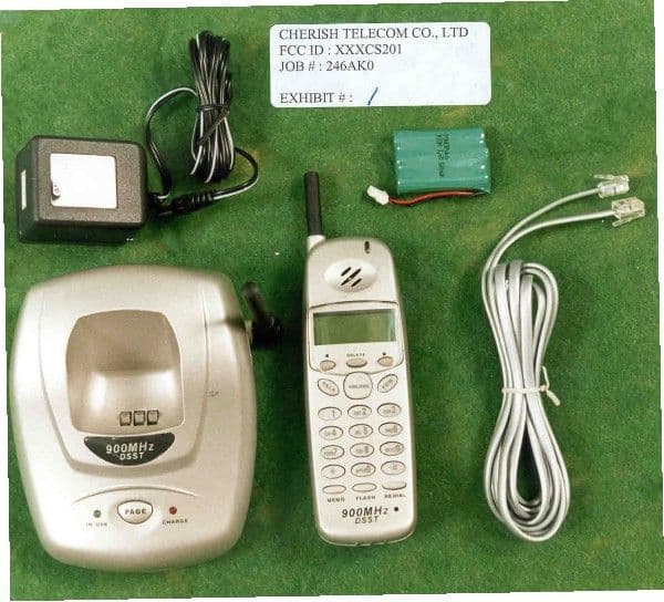
FNXCS201
Apr 08, 2001900 MHz DSSS Cordless Telphone With Caller ID
Equipment Class
DSS - Part 15 Spread Spectrum Transmitter
FNXCG-201
Feb 18, 20012.4GHz Analog Cordless Phone
Equipment Class
DXX - Part 15 Low Power Communication Device Transmitter
FNXCT-101
Dec 19, 20002.4 GHz spread spectrum CT
Equipment Class
DSS - Part 15 Spread Spectrum TransmitterFNXNCP-440CT
Sep 25, 1997ETS - Part 15 Cordless Telephone System
Equipment Class
ETS - Part 15 Cordless Telephone System