FNXCT-1012.4 GHz spread spectrum CT
Cherish Telecom Co Ltd
Click to zoom
Application Details
- Equipment Class
- DSS - Part 15 Spread Spectrum Transmitter
- Date of Grant
- Dec 19, 2000
- Application Purpose
- Original Equipment
- Date of Application
- Aug 20, 2000
- Equipment Note
- 2.4 GHz spread spectrum CT
- Frequency Range
- 2404.80000000 - 2474.90000000
- Company
- Cherish Telecom Co Ltd
- Country
- Taiwan
Documents & Files
Document Text
Text extracted from the exhibit documents filed with the FCC. Open a document above to read the original.
Cover Letter(s)
For your information As it stands, the revised manual info still contains a 50% duty factor and did not provide any duty factor info to support that claim. The instructions still contain the incorrect push-to-talk (in front of a person's face) operating procedures for this cordless phone that is held next to the ear. The user’s manual needs to agree with the usage of the device – please correct as this communication will be placed in the file.
RF Exposure Info
SAFETY INFORMATION FOR CT-101 Your cordless telephone contains a low power transmitter. When the Push-to Talk (PTT) button is pushed it sends out radio frequency (RF) signals. This device is authorized to operate at a duty factor not to exceed 50%. In August 1996, the Federal Communications Commission (FCC) adopted RF exposure guidelines with safety levels for hand-held wireless devices. CAUTION: To maintain compliance with the FCC’ s RF exposure guidelines, hold the transmitter and antenna at least 0.5 inches (1.25 centimeters) from your face with the antenna pointed up and away from the face. If you wear the handset on your body while using the headset accessory, use only the manufacturers supplied belt clip for this product and ensure that the antenna is at least 1 inches (2.5 centimeters) from your body when transmitting. Use only the supplied antenna. Unauthorized antennas, modifications, or attachments could damage the transmitter and may violate FCC regulations.
RF Exposure Info
TIMCO ENGINEERING, INC. 849 N.W. STATE ROAD 45 P.O. BOX 370 NEWBERRY, FLORIDA 32669 PHONE: 888-472-2424 OR 352-472-5500 FAX: 352-472-2030 EMAIL: [email protected] or [email protected] November 21, 2000 Mr. Errol Chang Federal Communicatio ns Co mmission Authorization and Evaluation Division 7435 Oakland Mills Road Columbia, MD 21046 REF: CHERISH TELECOM CO., LTD.’S FCC ID: FNXCT-101 CONFIRMATION #: EA98540 - YOUR CORRESPONDENCE ID # 17135 Dear Errol: With reference to correspondence ID 17135: The belt-clip is plastic and so is the case of the handset. This phone does have a headset option; while using the belt-clip, the end user can use a headset. With the belt-clip in place, the separation distance between the antenna and a person’s body is about 1 inch. Should you have any questions or require any further information, please advise. Regards, Sharon A. Hoffma n SAH/Hs T:\CUS\C\CHERISH\285K0\EC01121LTR.doc
RF Exposure Info
Operating Instruction for Satisfying RF Exposure Compliance Your cordless telephone contains a low power transmitter. When the Push-to-Talk button is pushed it sends out radio frequency (RF) signals. This device is authorized to operate at a duty factor not to exceed 50%. In August 1996, the Federal Communications Commission (FCC) adopted RF exposure guidelines with Safety levels for hand-held wireless devices. CAUTION: To maintain compliance with the FCC’s RF exposure guidelines, hold the transmitter and antenna at least 0.5 inches (1.25 centimeters) from your face with the antenna pointed up and away from the face. If you wear the handset on your body while using the headset accessory, use only the manufacturer’s supplied belt clip for this product and ensure that the antenna is at least 1 inch (2.5 centimeters) from your body when transmitting. This device and its antenna(s) must not be co-located or operated in conjunction with any other antenna or transmitter, use only the supplied antenna. Unauthorized antennas, modifications, or attachments could damage the transmitter and may violate FCC regulations. This phone device has an output power of maximum 19mW, which no warning statements required. Now this phone (device) is designed so that the antenna is at least 0.5 inches from your face. Therefore, this phone device satisfies RF exposure compliance.
Test Report
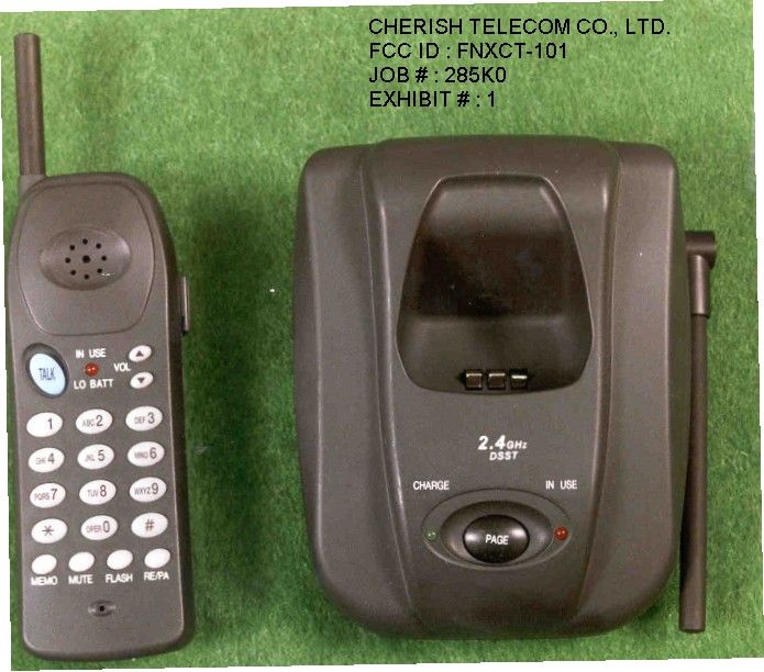
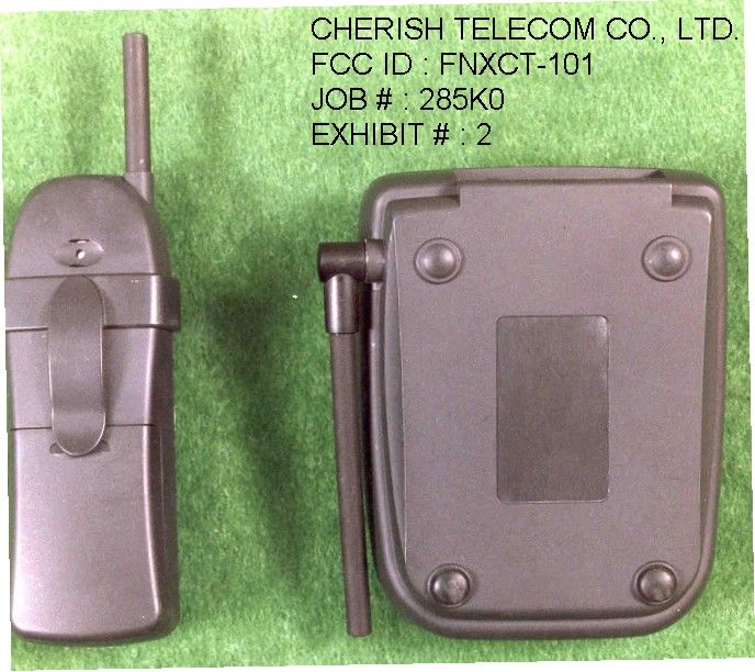
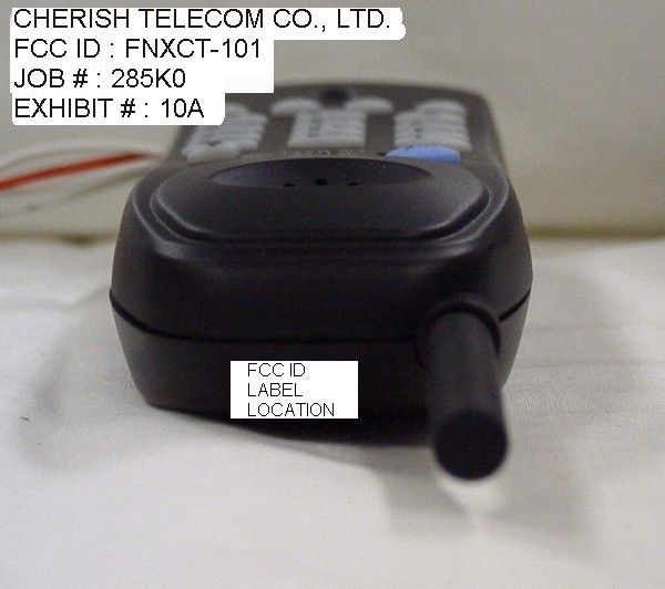
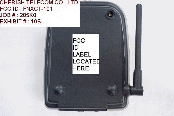
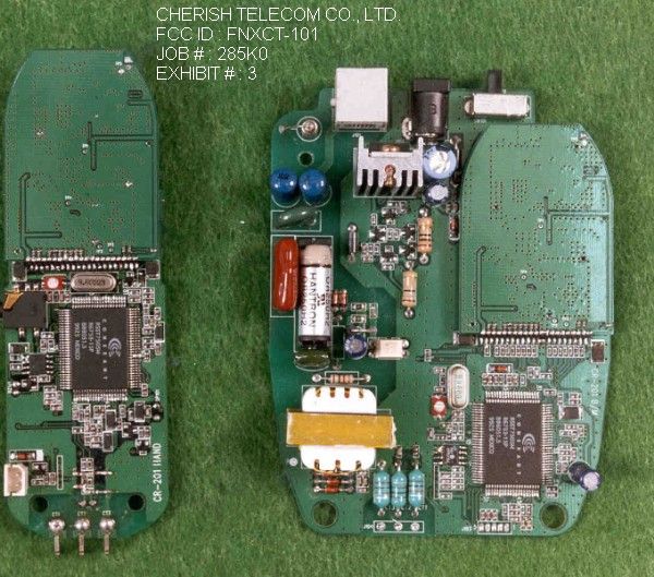
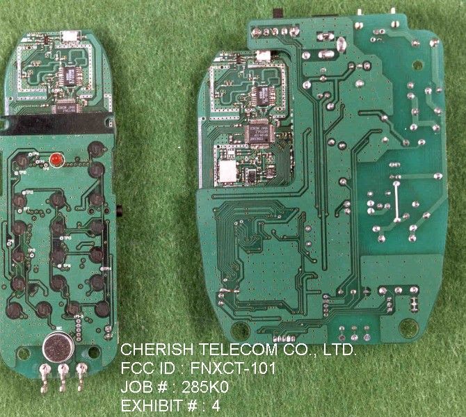
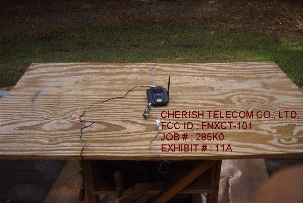
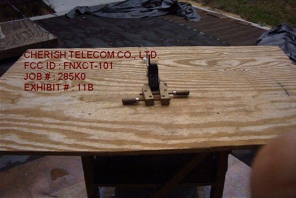
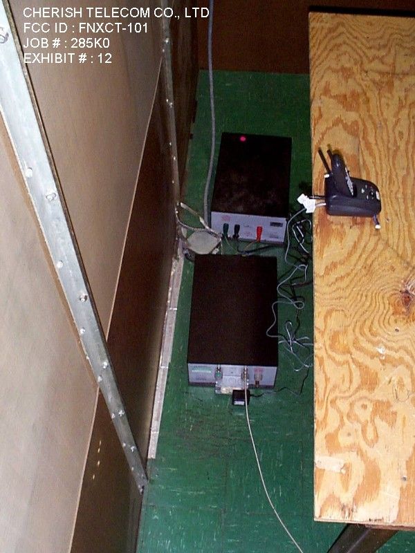
APPLICANT: CHERISH TELECOM CO., LTD. FCC ID: FNXCT-101 TABLE OF CONTENTS TEST REPORT CONTAINING: PAGE 1.............TEST PROCEDURE & EQUIPMENT LIST PAGE 2.............PRODUCT DESCRIPTION PAGE 3.............SECURITY CODING INFORMATION PAGE 4.............POWER LINE CONDUCTED EMISSIONS PAGE 5.............6dB BANDWIDTH PAGE 6.............POWER OUTPUT PAGE 7.............METHOD OF MEASURING RF CONDUCTED EMISSIONS AND SPURIOUS EMISSIONS AT ANTENNA TERMINALS PAGE 8.............FIELD STRENGTH OF SPURIOUS EMISSIONS PAGE 9.............METHOD OF MEASURING RADIATED SPURIOUS PAGE 10.............POWER SPECTRAL DENSITY EXHIBIT ATTACHMENTS: EXHIBIT 1...........FRONT VIEW EXTERNAL PHOTOS -BASE & HANDSET EXHIBIT 2...........REAR VIEW EXTERNAL PHOTOS -BASE & HANDSET EXHIBIT 3...........COMPONENT SIDE INTERNAL PHOTOS EXHIBIT 4...........COPPER SIDE INTERNAL PHOTOS EXHIBIT 5A-5C.......BLOCK DIAGRAMS- BASE & HANDSET EXHIBIT 6A..........SCHEMATIC - BASE MAIN EXHIBIT 6B..........SCHEMATIC - HANDSET MAIN EXHIBIT 6C..........SCHEMATIC - AMPLIFIER EXHIBIT 6D..........SCHEMATIC - TRANSCEIVER EXHIBIT 7A-7G.......USERS MANUAL EXHIBIT 8A-8C.......CIRCUIT DESCRIPTIONS EXHIBIT 9...........FCC ID LABEL SAMPLES EXHIBIT 10A-10B.....SKETCH OF LABEL LOCATIONS EXHIBIT 11A-11B.....TEST SET UP PHOTOS - RADIATED EMISSIONS EXHIBIT 12..........TEST SET UP PHOTO - POWERLINE CONDUCTED EXHIBIT 13A-13b.....POWERLINE CONDUCTED EMISSIONS PLOTS EXHIBIT 14A.........OCCUPIED B/W PLOT- CH 1 BASE - 6 dB B/W EXHIBIT 14B.........OCCUPIED B/W PLOT- CH 40 BASE - 6 dB B/W EXHIBIT 14C.........OCCUPIED B/W PLOT- CH 1 HANDSET - 6 dB B/W EXHIBIT 14D.........OCCUPIED B/W PLOT- CH 40 HANDSET - 6 dB B/W EXHIBIT 14E.........OCCUPIED B/W PLOT- CH 40 BASE - BANDEDGE EXHIBIT 14F.........OCCUPIED B/W PLOT- CH 40 HANDSET - BANDEDGE EXHIBIT 15A.........SPECTRAL DENSITY- CH 1 BASE - 20 dB ATT EXHIBIT 15B.........SPECTRAL DENSITY- CH 10 BASE - 20 dB ATT EXHIBIT 15C.........SPECTRAL DENSITY- CH 40 BASE - 20 dB ATT EXHIBIT 15D.........SPECTRAL DENSITY- CH 40 BASE - 42 dB ATT EXHIBIT 15E.........SPECTRAL DENSITY- CH 1 HANDSET - 42 dB ATT EXHIBIT 15F.........SPECTRAL DENSITY- CH 10 HANDSET - 42 dB ATT EXHIBIT 15G.........SPECTRAL DENSITY- CH 40 HANDSET - 42 dB ATT REPORT #: T:\CUS\C\CHERISH\285K0\285K0.RPT TABLE OF CONTENTS APPLICANT: CHERISH TELECOM CO., LTD. FCCID : FNXCT-101 TEST EQUIPMENT LIST 1._X_Spectrum Analyzer: HP 8566B-Opt 462, S/N 3138A07786, w/ preselector HP 85685A, S/N 3221A01400, Quasi-Peak Adapter HP 8565OA, S/N 3303A01690 & Preamplifier HP 8449B-OPT H02, S/N 3008A00372 Cal. 10/17/99 2._X_Biconnical Antenna: Eaton Model 94455-1, S/N 1057 3.___Biconnical Antenna: Electro-Metrics Model BIA-25, S/N 1171 4._X_Log-Periodic Antenna: Electro-Metrics Model EM-6950, S/N 632 5._X_Log-Periodic Antenna: Electro-Metrics Model LPA-30, S/N 409 6._X_Double-Ridged Horn Antenna: Electro-Metrics Model RGA-180, 1-18 GHz, S/N 2319 7._X_18-26.3GHz Systron Donner Standard Gain Horn #DBE-520-20 8.___Horn 40-60GHz: ATM Part #19-443-6R 9.___Line Impedance Stabilization Network: Electro-Metrics Model ANS-25/2, S/N 2604 Cal. 2/9/00 10.___Temperature Chamber: Tenney Engineering Model TTRC, S/N 11717-7 11.___Frequency Counter: HP Model 5385A, S/N 3242A07460 Cal 10/6/99 12.___Peak Power Meter: HP Model 8900C, S/N 2131A00545 13._X_Open Area Test Site #1-3meters Cal. 12/22/99 14.___Signal Generator: HP 8640B, S/N 2308A21464 Cal. 9/23/99 15.___Signal Generator: HP 8614A, S/N 2015A07428 16.___Passive Loop Antenna: EMCO Model 6512, 9KHz to 30MHz, S/N 9706-1211 Cal. 6/10/00 17.___Dipole Antenna Kit: Electro-Metrics Model TDA-30/1-4, S/N 153 Cal. 11/24/99 18.___AC Voltmeter: HP Model 400FL, S/N 2213A14499 Cal. 9/21/99 19.___Digital Multimeter: Fluke Model 8012A, S/N 4810047 Cal 9/21/99 20.___Digital Multimeter: Fluke Model 77, S/N 43850817 Cal 9/21/99 21.___Oscilloscope: Tektronix Model 2230, S/N 300572 Cal 9/23/99 TEST PROCEDURE GENERAL: This report shall NOT be reproduced except in full without the written approval of TIMCO ENGINEERING, INC. Shielded interface cables were used in all cases except for cables connecting to the telephone line and the power cords. A test program was run which simulated a normal data transmission on a network. POWER LINE CONDUCTED INTERFERENCE: The procedure used was ANSI STAN- DARD C63.4-1992 using a 50uH LISN. Both lines were observed with the UUT transmitting. The bandwidth of the spectrum analyzer was 10kHz with an appropriate sweep speed. The ambient temperature of the UUT was 95oF with a humidity of 45%. FCC ID: FNXCT-101 DATE: 28 JULY 2000 REPORT #: T:\CUS\C\CHERISH\285K0\285K0.RPT PAGE #: 1 TEST PROCEDURE CONTINUED BANDWIDTH 6.0dB: The measurements were made with the spectrum analyz- er's resolution bandwidth(RBW)=1.0MHz and the video bandwidth(VBW) =3.0MHz and the span set as shown on plot. POWER OUTPUT: The RF power output was measured at the antenna feed point using a peak power meter. ANTENNA CONDUCTED EMISSIONS: The RBW=100KHz, VBW=300KHz and the span set to 10.0MHz and the spectrum was scanned from 30MHz to the 10th Harmonic of the fundamental. Above 1.0GHz the resolution bandwidth was 1.0MHz and the VBW = 3.0MHz and the span to 50MHz. RADIATION INTERFERENCE: The test procedure used was ANSI STANDARD C63.4-1992 using a HEWLETT PACKARD spectrum analyzer with a prese- lector. The bandwidth(RBW) of the spectrum analyzer was 100kHz up to 1GHz and 1.0MHz above 1GHz with an appropriate sweep speed. The VBW above 1.0GHz was = 3.0MHz. The analyzer was calibrated in dB above a microvolt at the output of the antenna. The ambient temperature of the UUT was 95oF with a humidity of 45%. PRODUCT DESCRIPTION: The FNXCT-101 is a direct sequence spread spectrum cordless telephone radio that operates in the 2400-2483.5MHz band. The antenna used for the base and the handset is permanently attached to the UUT. In normal use the handset antenna is more than 2.5cm from the body(head), it is approximately 4.0cm. This UUT does not have a belt clip or connection for a…
Text truncated - open the document above for the full version.
Contact Information
Applicant
Peter Yeo(Vice President)
Technical Contact
Timco Engineering, Inc.Eric F Dobson
[email protected]888-472-2424
P.O. Box 370 · Newberry, Florida · United States
Non-Technical Contact
Timco Engineering, Inc.Eric F Dobson
[email protected]888-472-2424
Test Firm
Timco Engineering, Inc.S Sanders
Technical Specifications
| # | Rule Parts | Frequency Range | Power Output |
|---|---|---|---|
| 1 | 15C | 2.40 GHz - 2.47 GHz | 19.00 mW |
Other Applications from Cherish Telecom Co Ltd
FNXCS201
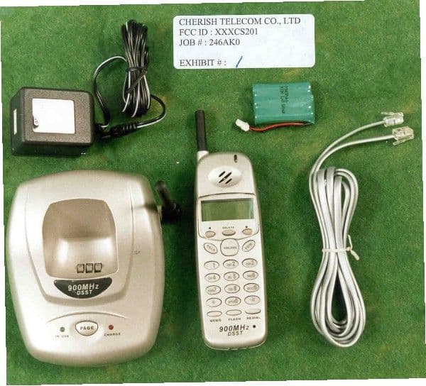
Apr 08, 2001900 MHz DSSS Cordless Telphone With Caller ID
Equipment Class
DSS - Part 15 Spread Spectrum Transmitter
FNXCG-201
Feb 18, 20012.4GHz Analog Cordless Phone
Equipment Class
DXX - Part 15 Low Power Communication Device Transmitter
FNXCR-252
Jul 20, 1999900 MHz DSSS Cordless Telephone
Equipment Class
DSS - Part 15 Spread Spectrum TransmitterFNXNCP-440CT
Sep 25, 1997ETS - Part 15 Cordless Telephone System
Equipment Class
ETS - Part 15 Cordless Telephone System