FYLHD5Multimedia Monitor
Sampo Corporation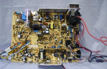
Click to zoom
Application Details
- Equipment Class
- JBP - Part 15 Class B Computing Device Peripheral
- Date of Grant
- Sep 12, 2000
- Application Purpose
- Original Equipment
- Date of Application
- Jul 31, 2000
- Equipment Note
- Multimedia Monitor
- Company
- Sampo Corporation
- Country
- Taiwan
Documents & Files
Document Text
Text extracted from the exhibit documents filed with the FCC. Open a document above to read the original.
Users Manual
MMM-0003 VER 1.0 34“ MULTIMEDIA MONITOR SERVICE MANUAL MODEL : :: : SME-32HD5 WARNING AND CAUTION - 1 - WARNING: TO PREVENT FIRE OR SHOCK HAZARD, DO NOT EXPOSE THIS MONITOR TO RAIN OR MOISTURE. HIGH VOLTAGE EXISTS ON THE CATHODE-RAY TUBE ANODE LEAD OF THIS MONITOR. BEFORE SERVICING, DETERMINE THE PRESENCE OF HIGH VOLTAGE BY CONNECTING THE H.V. METER BETWEEN THE ANODE OF CRT CAP AND CHASSIS ONLY. CAUTION: 1.Keep monitor away from excessive dust, high temperature, moisture or direct sunlight. 2.Use well ventilated area and do not cover ventilation openings. 3.Unauthorized modification to this equipment, substitution or the use of an unshielded connecting cable may cause excessive interference. 4.When the monitor is not in use, disconnect it from the mains power supply. 5.As an ENERGY STAR ® Partner, SAMPO CORPORATION has determined that this product meets the ENERGY STAR ® guidelines for energy efficiency . 6.If the picture display is in any way abnormal, disconnect from mains. Check and ensure the installation is correct . Then reconnect the mains supply. CAUTION RISK OF ELECTRIC SHOCK DO NOT OPEN CAUTION: TO REDUCE THE RISK OF ELECTRIC SHOCK, DO NOT REMOVE COVER (OR REAR) DO USER SERVICEABLE PARTS INSIDE REFER SERVICING TO QUALIFIED PERSONNEL IMPORTANT SAFETY INSTRUCTION - 2 - Prior to using this product, please ensure that you have carefully read and understood all the procedures outlined in this user’s manual. 1. Read all of these instructions. 2. Save these instructions for later use. 3. Follow all warnings and instructions marked on the product. 4. Disconnect from the mains supply before cleaning. Do not use liquid or aerosol cleaners. Use only a slightly damp cloth for cleaning. 5. Do not use this product near water. 6. Do not place this product on an unstable cart, stand or table. The product may fall, causing serious damage. 7. Slots and openings in the cabinet located at the back and underneath are provided for ventilation . To ensure reliable operation of the product and to protect it from overheating, these openings must not be blocked or covered. The openings should never be blocked by placing the product on a bed, sofa, rug, or other similar surface. This product should never be placed near or over a radiator or heat source. This product should not be placed in an enclosed installation unless proper ventilation is provided. 8. This product should be operated from the type of power source indicated on the marketing label. If you are not sure of the type of power available, consult your dealer or local power company. 9. This product is equipped with a 3-pin earthed plug, a plug having a third(grounding) pin. This plug will only fit into a grounding-type power outlet. This is a safety feature. If you are unable to insert the plug into the outlet, contact your electrician to replace your obsolete outlet. Do not defeat the purpose of the grounding-type plug. 10. Do not allow anything to rest on the power cord. Do not locate this product where persons will walk on or be tripped up by the cord. IMPORTANT SAFETY INSTRUCTION - 3 - 11. If an extension cord is used with this product, ensure that the total ampere ratings of the products connected to the extension cord, do not exceed the extension cord ampere rating. Also ensure that the total amperes of all products connected to the mains outlet, does not exceed 15 amperes. 12. Never push objects of any kind into this product through cabinet slots as they may touch dangerous voltage points or short out parts that could result in a risk of fire or electric shock. Never spill liquid of any kind on the product. 13. Do not attempt to service this product yourself, as opening or removing covers may expose you to dangerous voltage points or other risks. Refer all servicing to qualified service personnel. 14. Disconnect this product from the mains supply and refer servicing to qualified service personnel under the following conditions: A. When the power cord or plug is damaged or frayed. B. If liquid has been spilled into the product. C. If the product has been exposed to rain or water. D. If the product does not operate normally when the operating instructions are followed. Adjust only those controls that are covered by the operating instructions since improper adjustment of other controls may result in damage and will often require extensive work by a qualified technician to restore the product to normal operation. E. If the product has been dropped or the cabinet has been damaged. F. If the product exhibits a distinct change in performance, indicating a need for service. Wichtige Sicherheitshinweise - 4 - 1. Bitte lesen Sie sich diese Hinweise sorgf ä ltig durch. 2. Heben Sie diese Anleitung f ü r den sp ä teren Gebrauch auf. 3. Vor jedem Reinigen ist das Ger ä t vom Stromnetz zu trennen. Verwenden Sie keine Fl ü ssig- oder Aerosolreiniger. Am besten dient ein angefeuchtetes Tuch zur Reinigung. 4. Umeine Besch ä digung des Ger ä tes zu vermeiden sollten Sie nur Zubeh ö rteile verwenden, die vom Hersteller zugelassen sind. 5. Das Ger ä t ist vor Feuchtigkeit zu sch ü tzen. 6. Bei der Aufstellung des Ger ä tes ist auf sicheren Stand zu achten. Ein Kippen oder Fallen k ö nnte Verletzungen hervorrufen. Verwenden Sie nur sichere Standorte und beachten Sie die Aufstellhinweise des Herstellers. 7. Die Bel ü ftungs ö ffnungen dienen zur Luftzirkulation die das Ger ä t vor Ü berhitzung sch ü tzt. Sorgen Sie daf ü r, da ß diese Ö ffnungen nicht abgedeckt werden. 8. Beachten Sie beim Anschlu ß an das Stromnetz die Anschlu ß werte. 9. Die Netzanschlu ß steckdose mu ß aus Gr ü nden der elektrischen Sicherheit einen Schutzleiterkontakt haben. 10. Verlegen Sie die Netzanschlu ß leitung so, da ß niemand dar ü ber fallen kann. Es sollte auch nichts auf der Leitung abgestellt werden. 11. Alle Hinweise und Warnungen die sich am Ger ä ten befinden sind zu beachten. 12. Wird das Ger ä t uber einen l ä ngeren Zeitraum nicht benutzt, sollten Sie es vom Stromnetz t…
Text truncated - open the document above for the full version.
ID Label/Location Info
HomeTek Technology Inc. FB9F012 Appendix A : Label Location LABEL LOCATION 5 of 5
ID Label/Location Info
samp (9096x4592x256 jpeg)
Internal Photos
HomeTek Technology Inc. FD9F012 Appendix B : PHOTO OF EUT Rear View of EUT Front View of EUT 1 of 9 HomeTek Technology Inc. FD9F012 Appendix B : PHOTO OF EUT Inside View of EUT 2 of 9 Rear View of CRT HomeTek Technology Inc. FD9F012 Appendix B : PHOTO OF EUT Main Board Component Side View of EUT Main Board Solder Side View of EUT 3 of 9 HomeTek Technology Inc. FD9F012 Appendix B : PHOTO OF EUT Component Side View of CRT Board 4 of 9 Solder Side View of CRT Board HomeTek Technology Inc. FD9F012 Appendix B : PHOTO OF EUT 5 of 9 Component Side View of I/O Board Solder Side View of I/O Board HomeTek Technology Inc. FD9F012 Appendix B : PHOTO OF EUT Solder Side View of V & H Sync. Board 6 of 9 Component Side View of V & H Sync. Board HomeTek Technology Inc. FD9F012 Appendix B : PHOTO OF EUT 7 of 9 Component Side View of Audio Amplifier Solder Side View of Audio Amplifier HomeTek Technology Inc. FD9F012 Appendix B : PHOTO OF EUT Component Side View of Control Board 8 of 9 Solder Side View of Control Board HomeTek Technology Inc. FD9F012 Appendix B : PHOTO OF EUT Full View of Data Cable 9 of 9
Schematics
BLOCK DIAGRAM VER 1.0 6 6 6 6- - - - 2 2 2 2 Total block diagram L Ϩ R Ϩ V Ϩ AV1 L Ϩ R Ϩ V Ϩ AV2 L Ϩ R Ϩ V Ϩ AV OUT S I/P RGB I/P DEF. BLOCK AUX POWER POWER Ϥ Ϥ Ϥ AC LINE H V AV BLOCK R L L V R PHONE TDA2616 SOUND AMP TA8184 SOUND CONTROL CRT AMP CRT R B G YCBCR YPBPR BLOCK DIAGRAM VER 1.0 6 6 6 6- - - -2 2 2 2 Monitor DEF. & CRT AMP block diagram Main Board si g nals out p ut R B G H V PC87C380 IC001 TDA4854 (DEF.IC) IC691 IIC BUS H V RGB/TV Dynamic Focus:IC6C1 74HC221:IC631 AMP/DAMP:Q601,T601 Sidepin:Q6I1,6I2,L6I1 V0 V2 V1 SB SB1 H-size DC-converter:T604,Q6D4 AMP/DAMP:Q6C9,C6D2 V-AMP TDA8351:IC501 FBT T6C2 Cs linear C608,609,L601,602 LM358 IC632 3843 IC661 DC converter IRF740:T604 H-DEF Feedback R674,675,676 H.V. Feedback FOCUS H.V. 31KV MAIN BOARD POWER CIRCUIT 205V 28V 190V 13V 19V 6.3V AC IN Sub power and Sound board TDA4885: IC901 AMP:Q903,905,907 CRT BOARD H-YOKE V-YOKE H.V. CRT C O N T R O L B U S H.V. H V H V R L BLOCK DIAGRAM VER 1.0 6 6 6 6- - - -3 3 3 3 Main power supply & Aux. power & sound AMP block diagram AC Input EMI Filter T702,T703 DEGA IC713 Bridge & Rectifier BR701 Low Voltage Protection Q711,Q712,Q713 PWM IC IC711 DC Switch IC716~D788 T781 Rectifier & Filter:IC781 Rectifier & Filter:D790 Rectifier & Filter:D789 30V Stand by +5V Stand by +12V X‘ FMR T701 Protect Rectifier & Filter:D757 Rectifier & Filter:D755 Rectifier & Filter:D756 Rectifier & Filter:D759 Rectifier & Filter:D753 6.3V (0.63A) SB1 CPU pin20 19V (0.4A) 13V (0.4A) 28V (0.2A) 205V (0.6A) TA8184 IC301 R L Pre-AMP IC302~309 AMP TDA2616 IC311 TO CPU Sound Sound control Rectifier & Filter:L751 190V (0.11A) Sevices Regulator Feedback Network IC712 SB CPU pin28 SPEAKERS BLOCK DIAGRAM VER 1.0 6 6 6 6- - - -4 4 4 4 AV. Board AV1 AV2 RGB I/P S I/P AV OUT AV SWITCH IC806 IC807 TC9090AN V IC801 TB1276AN SOUND BLOCK See Pa g e5 Sound ( R ) Sound ( L ) 5V 9V R/G/B/H/V ( VGA ) R H to Main board to CPU G B V R L V R L V V R L C Y VIDEO SWITCH IC803 YCBCR YPBPR YUV
Test Report
HomeTek Technology Inc. FCC ID : FYLHD5 FB9F012 TABLE OF CONTENTS GENERAL INFORMATION ..........................................................................................................................................2 MODIFICATION LIST ...................................................................................................................................................4 CONDUCTED POWER LINE TEST .............................................................................................................................5 1TEST INSTRUMENTS & FACILITIES.........................................................................................................5 2TEST PROCEDURE .......................................................................................................................................5 3TEST SETUP...................................................................................................................................................6 4CONFIGURATION OF THE EUT .................................................................................................................8 5EUT OPERATING CONDITION .................................................................................................................11 6LIMIT OF CONDUCTED POWER LINE EMISSION CLASS B : .............................................................11 7RESULT OF CONDUCTED POWER LINE TEST (1)................................................................................12 8RESULT OF CONDUCTED POWER LINE TEST (2)................................................................................13 RADIATED EMISSION TEST .....................................................................................................................................14 1TEST INSTRUMENTS & FACILITIES.......................................................................................................14 2TEST PROCEDURE .....................................................................................................................................15 3TEST SETUP.................................................................................................................................................15 4CONFIGURATION OF THE EUT ...............................................................................................................16 5EUT OPERATING CONDITION .................................................................................................................16 6LIMIT OF RADIATED EMISSION CLASS B : ..........................................................................................16 7RESULT OF RADIATED EMISSION TEST (1) .........................................................................................17 8RESULT OF RADIATED EMISSION TEST (2) .........................................................................................19 PHOTO OF FCC ID LABEL.........................................................................................................................................21 APPENDIX A PHOTOS OF TEST CONFIGURATION APPENDIX B PHOTOS OF EUT HomeTek Technology Inc. FCC ID : FYLHD5 FB9F012Page : 2 of 21 GENERAL INFORMATION 1APPLICANT: SAMPO CORPORATION 2ADDRESS : 216, Chung Shan Road, Sec. 1, Pan Chiao City, Taipei Hsien, Taiwan, R. O. C. 3MANUFACTURER : SAMPO CORPORATION 4ADDRESS : 216, Chung Shan Road, Sec. 1, Pan Chiao City, Taipei Hsien, Taiwan, R. O. C. 5DESCRIPTION OF EUT : EUT: Multimedia Monitor FCC ID: FYLHD5 Model Number: SME-32HD5, SME-32HDXXXX, SME-32SDXXXX, SM-34HDXXXX, DTV34XHXXXX, VC-34MXXXX, XV-34HDXXXX (X=0~9, A~Z or Blank) Serial #: N/A Data Cable: N/A Power Cord: UN-SHIELDED Power Supply Type: SWITCHING 5.1The difference between series models of SAMPO Multimedia monitor is for different OEM customer. The internal circuit and P. C. B. Layout and function is the same. HomeTek Technology Inc. FCC ID : FYLHD5 FB9F012Page : 3 of 21 6FEATURES OF EUT : 6.1Cathode ray tube a. tube size: b. Dot pitch: c. Light transmission: 34 inch (32 inch viewable) H=0.8mm 35% typical 6.2Power a. Input voltage: b. Input current: c. Power consumption: 100Vac~240Vac 60Hz/50Hz Max 3A at 110Vac / 60Hz Max 220 Watts (Max) 6.3Input signal Video signal a. Type: b. Polarity: c. Amplitude: d. Input impedance: e. Dot rate: Analog Positive RGB: 0.7 Vp-p/AV:1.0 Vp-p 75 ohms 65 MHz (Max.) 6.4Horizontal sync a. Type: b. Polarity: c. Input impedance: d. Frequency: TTL Positive or negative 1K ohm (Min) RGB: 31KHz to 52 KHz AV: 15.734 KHz (NTSC) / 60Hz 6.5Vertical sync a. Type: b. Polarity: c. Input impedance: d. Frequency: TTL Positive or negative 1K ohm (Min) 50 Hz to 120Hz 6.6Connector type:15 pin D-type and RCA JACK and S-terminal 6.7Standard size Horizontal size: Vertical size: 620 + / - 8 mm 465 + / - 8 mm 6.8Unit dimension (with base): Packaging dimension: W (886) x H (718) x D (583) W (1035) x H (888) x D (765) HomeTek Technology Inc. FCC ID : FYLHD5 FB9F012Page : 4 of 21 MODIFICATION LIST THE FOLLOWING ACCESSORIES WERE ADDED TO THE EUT DURING TESTING : NO MODIFICATION BY HOMETEK TECHNOLOGY INC. HomeTek Technology Inc. FCC ID : FYLHD5 FB9F012Page : 5 of 21 CONDUCTED POWER LINE TEST 1TEST INSTRUMENTS & FACILITIES The following test Instruments was used during the conducted test : Item Instruments/ Facilities SpecificationManufacturerModel # Date Of Cal. 1EMI Receiver9KHz ~ 30MHz ROHDE & SCHWARZ ESHS 30MAR/2000 2LISN 50Ω/50uH/100A 9KHz ~ 30MHz SCHWARZ BECK NNLK 8121 MAR/2000 3LISN9KHz ~ 30MHz ROHDE & SCHWARZ ESH3-Z5MAR/2000 4ESXS-K1Version 2.03b ROHDE & SCHWARZ 1082.9678.02 840.913/246 N/A 5Cables10KHz ~ 30MHz NO : 10 JUL/99 2TEST PROCEDURE 2.1 The EUT was tested according to ANSI C63.4 - 1992 & CISPR 22. 2.2 The EUT was placed 0.4 meter from the conducting wall of shielding room and kept at least 0.8 meter from any other grounded conducting surface. 2.3 The frequency range form 0.15 MHz to 30 MHz was investigated. 2.4 The LISN used was 50 Ohm / 50 uHenry as sp…
Text truncated - open the document above for the full version.
Test Setup Photos
HomeTek Technology Inc. FD9F012 Appendix A : PHOTO OF CONDUCTED POWER LINE TEST Rear View Front View 1 of 4 Test Mode : AV HomeTek Technology Inc. FD9F012 Appendix A : PHOTO OF CONDUCTED POWER LINE TEST Rear View Front View 2 of 4 Test Mode : PC HomeTek Technology Inc. FD9F012 Appendix A : Front View Rear View 3 of 4 PHOTO OF RADIATED EMISSION TEST Test Mode : AV HomeTek Technology Inc. FD9F012 Appendix A : Front View Rear View 4 of 4 PHOTO OF RADIATED EMISSION TEST Test Mode : PC
Contact Information
Applicant
Wen Huei Huang(Manager)
Technical Contact
Non-Technical Contact
HomeTek Technology Inc.Chu-Lin Chu
[email protected]408-7201661
Test Firm
Home Tek Technology Inc.Grant Huang
Technical Specifications
| # | Rule Parts | Frequency Range | Power Output |
|---|---|---|---|
| 1 | 15B | - | - |
Other Applications from Sampo Corporation
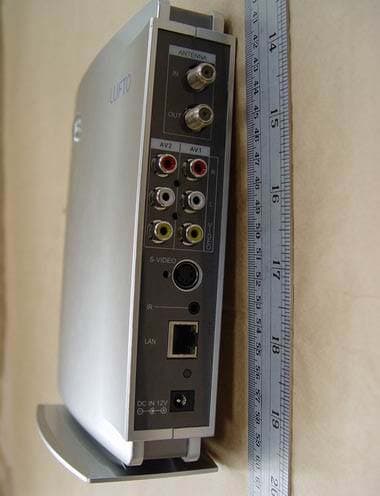
FYLWVR100
Mar 19, 2006Wireless AV Transmitter
Equipment Class
DTS - Digital Transmission System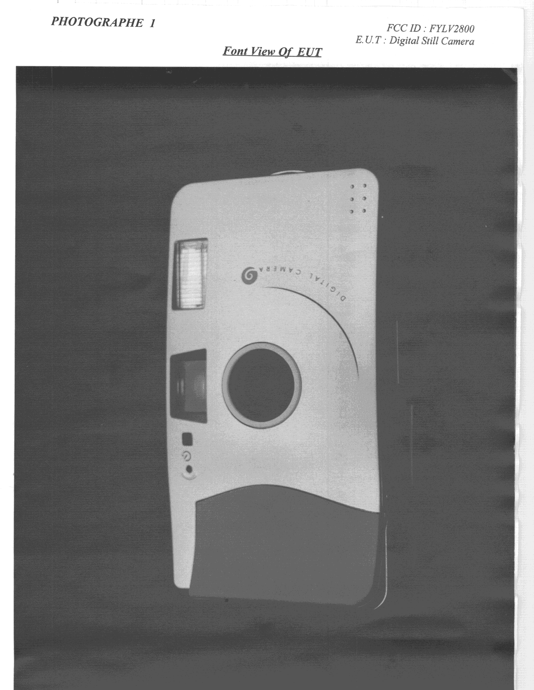
FYLV2800
Apr 26, 1999JBP - Part 15 Class B Computing Device Peripheral
Equipment Class
JBP - Part 15 Class B Computing Device Peripheral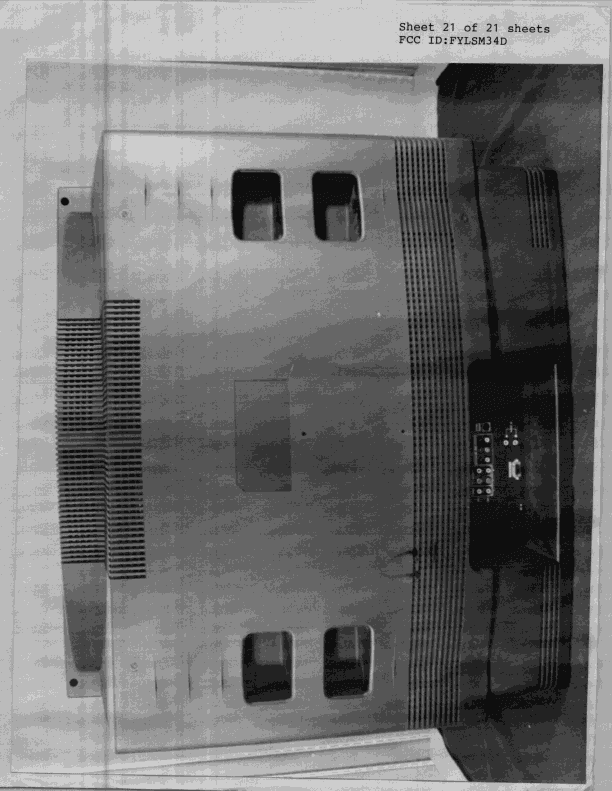
FYLSM34D
Jan 05, 1999JBP - Part 15 Class B Computing Device Peripheral
Equipment Class
JBP - Part 15 Class B Computing Device PeripheralFYLSTB21
Mar 10, 1998JBP - Part 15 Class B Computing Device Peripheral
Equipment Class
JBP - Part 15 Class B Computing Device PeripheralFYLSM72D
Feb 10, 1998Color Monitor The optional tuner box is not covered under this grant.
Equipment Class
JBP - Part 15 Class B Computing Device Peripheral