G95-TC8737CCable Modem
Vantiva USA LLC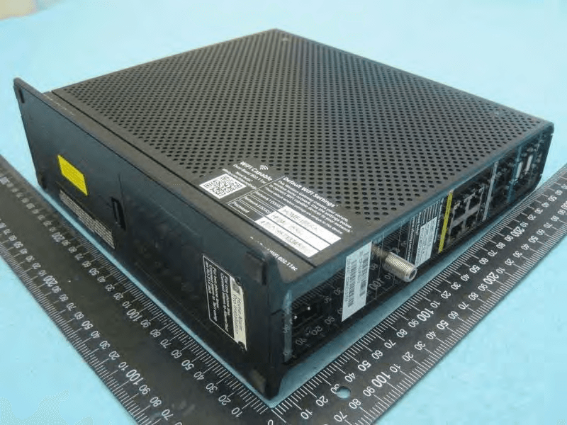
Click to zoom
Application Details
- Equipment Class
- DTS - Digital Transmission System
- Date of Grant
- Apr 21, 2015
- Application Purpose
- Original Equipment
- Date of Application
- Apr 21, 2015
- Equipment Note
- Cable Modem
- Frequency Range
- 2412.00000000 - 2462.00000000
- Company
- Vantiva USA LLC
- Country
- United States
Documents & Files
Document Text
Text extracted from the exhibit documents filed with the FCC. Open a document above to read the original.
Users Manual
cable VOICE DATA VIDEO Mediaaccess Tc8737cOX for cox communications Wireless .11ac Ultra-Speed Smart Cable Gateway with Battery Backup Solution Features at a Glance ■DOCSIS® 3.0 ■Backwards compatible with DOCSIS® 2.0 (and older) ■24 downstream and 8 upstream channels ■Full Band Capture / Spectral Analysis ■Switchable triplexer for Upstream Low and Mid split ■4 GE LAN ports ■Dual band concurrent Wi-Fi interfaces: IEEE 802.11n 2.4 GHz (3x3) High Power IEEE 802.11ac 5 GHz (3x3) High Power ■MoCA 2.0 ■2 FXS ports for phone or fax ■Voice PacketCable™ 1.5 & 2.0 compliant ■2 USB 2.0 master ports ■Seamless media sharing (UPnP A/ V™ and DLNA®) ■HNAP for home security services (optional) ■MPEG2 over IP encapsulation solution ■Future-proof full service platform supporting: Dedicated applications core ■TR-069 remote management ■IPv4 & IPv6 enabled ■Designed according to the latest ECO standards latest High-bandwidth Technology The TC8737COX is a DOCSIS 3.0 wireless embedded Multimedia Terminal Adapter (eMTA) smart gateway with best-in-class performance. A dedicated applications processor and software execution environment make it a powerful and reliable platform in the home, ready for demanding services and applications. The TC8737COX has an extended life cycle thanks to its extensive remote management capabilities, including the ability to smoothly upgrade itself and add apps on the go. Moreover, this new generation of smart high-speed data service solutions supports up to 24 bonded downstream channels and 8 bonded upstream channels for speeds of up to 930 Mbps downstream and 216 Mbps upstream. The TC8737COX incorporates a switchable triplexer for upstream filter to switch between low and mid-split filters. The TC8737COX also provides full connectivity to devices in the home including set-top boxes via MoCA. Next-Gen Wireless Technology for Next-Gen Speeds Featuring the next-generation IEEE 802.11ac wireless standard for the 5 GHz band, this dual band Wi-Fi solution makes optimal use of the wireless spectrum. With its optimized antenna configuration, the TC8737COX enables even higher throughput and better coverage over the much less crowded 5 GHz radio, for real-time content delivery. At the same time, it guarantees uninterrupted transmission of data services over IEEE 802.11n using the 2.4 GHz band. AV 24 x 8 Mediaaccess Tc8737cOX for cox communications Wireless .11ac Ultra-Speed Smart Cable Gateway with Battery Backup Solution Full band capture Solution Thanks to its fully integrated 1 GHz wideband capture and spectral analysis, the TC8737COX exceeds SCTE-40+ performance and eliminates all frequency limitations of traditional wideband tuners. The TC8737COX enables use of the full radio frequency (RF) spectrum without the need for grouped channels. This helps the operator migrate its entire DOCSIS 3.0 install base from one to 24 DOCSIS downstream channels without having to re-align all its broadband channels to accommodate this new service. Remote diagnostics provides real time, unobtrusive diagnostic and spectrum analysis capabilities, without effecting user service on any of the 24 downstream channels. applications core As an easily updatable platform, the TC8737COX is capable of providing subscribers with advanced services and apps within the home. Its dedicated applications processor and software service framework put services such as the following at your fingertips: ■Home Security and Automation ■Troubleshooting and Diagnostics ■Customer Self Help Moca The TC8737COX also includes an integrated MoCA 2.0 interface which enables the gateway to provide connectivity to set-top boxes and client devices connected within the home. Voice Performance The TC8737COX is PacketCable 1.5 and 2.0 compliant, and is equipped with basic and extended CLASS features such as caller id and call waiting. Video Streaming The TC8737COX contains an MPEG2 to IP encapsulation solution allowing the capture of the DVB-C free-to-air video signal on the RF network and the distribution of this video signal over IP on the local network of the customer. This feature is available upon software upgrade of the TC8737COX and is a first step for cable operator towards distributing IPTV without any change to their existing QAM (digital video) broadcast infrastructure. advanced Security The integrated firewall provides Stateful Packet Inspection (SPI), and an integrated intrusion detection and Prevention System (IDS) engine monitors a wide range of attack patterns, and logs potential security breaches to a local cache or remote server. To secure data exchange between the gateways and the cable operators’ servers, BPi+ communications privacy is used. easy to Use Like all Technicolor modems and gateways, the TC8737COX is an easy to use, easy to install gateway. For convenience of the end user, the easy-to-access LEDs provide a clear indication of start-up sequence, operational status, and connectivity status. Multiple integrated web pages also allow direct access to the status and settings, including privacy and security information. IPv6 enabled With the approaching IPv4 address pool depletion, our products need to be ready for IPv6. Technicolor is a frontrunner in the introduction of IPv6 on its devices, with the TC8737COX being enabled for multiple IPv6 field scenarios. Internet Protocol version 6 is the next generation of Internet technologies aiming to effectively support the ever-expanding Internet usage and functionality, and also to address security concerns that exist in an IPv4 environment. Technicolor aims to introduce IPv6 as smoothly as possible in customer networks. By providing in-depth knowledge of the networking stack, we guide our customers in their transition from IPv4 to IPv6. Media Sharing The TC8737COX acts as a fully compliant DLNA 1.5 Digital Media Server (DMS) and enables distribution of all content from any device to any device in the home. You can stream music, data, pictures and video from your gateway to dev…
Text truncated - open the document above for the full version.
Users Manual
SAFETY INSTRUCTIONS AND REGULATORY NOTICES BEFORE YOU START INSTALLATION OR USE OF THIS PRODUCT, CAREFULLY READ THESE INSTRUCTIONS Directive Unless express and prior approval by Technicolor in writing, you may not: Disassemble, de-compile, reverse engineer, trace or otherwise analyse the equipment, its content, operation, or functionality, or otherwise attempt to derive source code (or the underlying ideas, algorithms, structure or organization) from the equipment, or from any other information provided by Technicolor, except to the extent that this restriction is expressly prohibited by local law; Copy, rent, loan, re-sell, sub-license, or otherwise transfer or distribute the equipment to others; Modify, adapt or create a derivative work of the equipment; Remove from any copies of the equipment any product identification, copyright or other notices; Disseminate performance information or analysis (including, without limitation, benchmarks) from any source relating to the equipment. Such acts not expressly approved by Technicolor will result in the loss of product warranty and may invalidate the user's authority to operate this equipment in accordance with FCC Rules. Technicolor disclaims all responsibility in the event of use that does not comply with the present instructions. Environmental information The batteries use some hazardous substances which pollute the environment. Do not dispose of them with other articles. Take care to dispose them at special collecting points. Safety instructions Climatic conditions This product: Is intended for in-house stationary desktop use; the maximum ambient temperature may not exceed 40°C (104°F). Must not be mounted in a location exposed to direct or excessive solar and/or heat radiation. ! When using this product, always follow the basic safety precautions to reduce the risk of fire, electric shock and injury to persons, including the following: Always install the product as described in the documentation that is included with your product. Avoid using this product during an electrical storm. There may be a remote risk of electric shock from lightning. Do not use this product to report a gas leak in the vicinity of the leak. Must not be exposed to heat trap conditions and must not be subjected to water or condensation. Batteries (battery pack or batteries installed) shall not be exposed to excessive heat such as sunshine, fire or the like. Must be installed in a Pollution Degree 2 environment (Environment where there is no pollution or only dry, nonconductive pollution). Cleaning Unplug this product from the wall socket and computer before cleaning. Do not use liquid cleaners or aerosol cleaners. Use a damp cloth for cleaning. Water and moisture Do not use this product near water, for example near a bathtub, washbowl, kitchen sink, laundry tub, in a wet basement or near a swimming pool. Transition of the product from a cold environment to a hot one may cause condensation on some of its internal parts. Allow it to dry by itself before re-starting the product. Interface classifications The external interfaces of the product are classified as follows: Phone: TNV circuit, not subjected to over voltages (TNV-2) Cable, MoCA, RF: TNV circuit subject to overvoltages (TNV-1) All other interface ports (e.g. Ethernet, USB, etc.), including the low voltage power input from the AC mains power supply: SELV circuits. Electrical powering The powering of the product must adhere to the power specifications indicated on the marking labels. USB The device is to be connected to an identified USB port complying with the requirements of a Limited Power Source. Accessibility The plug on the power supply cord serves as disconnect device. Be sure that the power socket outlet you plug the power cord into is easily accessible and located as close to the equipment as possible. Overloading Do not overload mains supply socket outlets and extension cords as this increases the risk of fire or electric shock. Servicing To reduce the risk of electric shock, do not disassemble this product. None of its internal parts are user-replaceable; therefore, there is no reason to access the interior. Opening or removing covers may expose you to dangerous voltages. Incorrect reassembly could cause electric shock if the appliance is subsequently used. If service or repair work is required, take it to a qualified service dealer. Damage requiring service Unplug this product from the wall outlet and refer servicing to qualified service personnel under the following conditions: When the power supply or its plug are damaged. When the attached cords are damaged or frayed. If liquid has been spilled into the product. If the product has been exposed to rain or water. If the product does not operate normally. If the product has been dropped or damaged in any way. There are noticeable signs of overheating. If the product exhibits a distinct change in performance. Immediately disconnect the product if you notice it giving off a smell of burning or smoke. Under no circumstances must you open the equipment yourself; you run the risk of electrocution. Regulatory information You must install and use this device in strict accordance with the manufacturer's instructions as described in the user documentation that is included with your product. Before you start installation or use of this product, carefully read the contents of this document for device specific constraints or rules that may apply in the country where you want to use this product. In some situations or environments, the use of wireless devices may be restricted by the proprietor of the building or responsible representatives of the organization. If you are uncertain of the policy that applies on the use of wireless equipment in a specific organization or environment (e.g. airports), you are encouraged to ask for authorization to use this device prior to turning on the equipment. Technicolor is not responsible for any radio…
Text truncated - open the document above for the full version.
External Photos
Report No.:510501 SPORTON International Inc. PAGE NUMBER : C1 OF C7 TEL : 886-3-327-3456 FAX : 886-3-327-0973 APPENDIX C. Photographs of EUT Report No.:510501 SPORTON International Inc. PAGE NUMBER : C2 OF C7 TEL : 886-3-327-3456 FAX : 886-3-327-0973 Report No.:510501 SPORTON International Inc. PAGE NUMBER : C3 OF C7 TEL : 886-3-327-3456 FAX : 886-3-327-0973 Report No.:510501 SPORTON International Inc. PAGE NUMBER : C4 OF C7 TEL : 886-3-327-3456 FAX : 886-3-327-0973 Report No.:510501 SPORTON International Inc. PAGE NUMBER : C5 OF C7 TEL : 886-3-327-3456 FAX : 886-3-327-0973 AC power cord Report No.:510501 SPORTON International Inc. PAGE NUMBER : C6 OF C7 TEL : 886-3-327-3456 FAX : 886-3-327-0973 Lithium Ion Battery Model Name: BP-TC8-22/2250 S Report No.:510501 SPORTON International Inc. PAGE NUMBER : C7 OF C7 TEL : 886-3-327-3456 FAX : 886-3-327-0973
ID Label/Location Info
Package style Product Information barcode label U46C222.12 xueping Linda Fan Linda Fan 14.09.0200 14.09.02Update FCC ID01 Sunny 500.01762.005 TC8737C NOTES: 1.Surface Material:50#壓花Mylar (embossing) * 2.Surface Material tolerance:0.052±0.004mm 3.Surface Material color:white 4.printing color is as color defined in artwork 5.Adhesive base:Synthetic Resin * 6.Adhesive thickness:0.033+/-0.003mm * 7.Adhesion to steel(180o磨钢粘着力):1.0-2.2 kg/inch * 8.Initial Tack(初期力):1-6# 9.Relese Power(90o剥离力):4-20 g/in * 10.Holding Power(持粘力測試法):minimum 1hr/kg*inch2 11.Package Style:Reel 12.When label is adhesived on housing smooth face(material ABS) after it is tested under test condition -40~70°C 90%R.H. 72hrs, it must be fine. 13.This part must comply with ROHs. 50#壓花白Mylar(embossing) SCALE:1:1 車縫線 出 紙 方 向 41mm 18mm 4R=2.5mm 74.5mm 59.5mm 65.5 I.T.E. E199598 I.T.E. E199598 I.T.E. E199598 TC8737C G95-TC8737C TC8737C G95-TC8737C 空白Label允許0.5mm 黑邊 Label Here
Internal Photos
Report No.:510501 SPORTON International Inc. PAGE NUMBER : C1 OF C23 TEL : 886-3-327-3456 FAX : 886-3-327-0973 APPENDIX C. Photographs of EUT Report No.:510501 SPORTON International Inc. PAGE NUMBER : C2 OF C23 TEL : 886-3-327-3456 FAX : 886-3-327-0973 Report No.:510501 SPORTON International Inc. PAGE NUMBER : C3 OF C23 TEL : 886-3-327-3456 FAX : 886-3-327-0973 Report No.:510501 SPORTON International Inc. PAGE NUMBER : C4 OF C23 TEL : 886-3-327-3456 FAX : 886-3-327-0973 Report No.:510501 SPORTON International Inc. PAGE NUMBER : C5 OF C23 TEL : 886-3-327-3456 FAX : 886-3-327-0973 Report No.:510501 SPORTON International Inc. PAGE NUMBER : C6 OF C23 TEL : 886-3-327-3456 FAX : 886-3-327-0973 Report No.:510501 SPORTON International Inc. PAGE NUMBER : C7 OF C23 TEL : 886-3-327-3456 FAX : 886-3-327-0973 Report No.:510501 SPORTON International Inc. PAGE NUMBER : C8 OF C23 TEL : 886-3-327-3456 FAX : 886-3-327-0973 Report No.:510501 SPORTON International Inc. PAGE NUMBER : C9 OF C23 TEL : 886-3-327-3456 FAX : 886-3-327-0973 Report No.:510501 SPORTON International Inc. PAGE NUMBER : C10 OF C23 TEL : 886-3-327-3456 FAX : 886-3-327-0973 Report No.:510501 SPORTON International Inc. PAGE NUMBER : C11 OF C23 TEL : 886-3-327-3456 FAX : 886-3-327-0973 Report No.:510501 SPORTON International Inc. PAGE NUMBER : C12 OF C23 TEL : 886-3-327-3456 FAX : 886-3-327-0973 Report No.:510501 SPORTON International Inc. PAGE NUMBER : C13 OF C23 TEL : 886-3-327-3456 FAX : 886-3-327-0973 Report No.:510501 SPORTON International Inc. PAGE NUMBER : C14 OF C23 TEL : 886-3-327-3456 FAX : 886-3-327-0973 Report No.:510501 SPORTON International Inc. PAGE NUMBER : C15 OF C23 TEL : 886-3-327-3456 FAX : 886-3-327-0973 Report No.:510501 SPORTON International Inc. PAGE NUMBER : C16 OF C23 TEL : 886-3-327-3456 FAX : 886-3-327-0973 Report No.:510501 SPORTON International Inc. PAGE NUMBER : C17 OF C23 TEL : 886-3-327-3456 FAX : 886-3-327-0973 Report No.:510501 SPORTON International Inc. PAGE NUMBER : C18 OF C23 TEL : 886-3-327-3456 FAX : 886-3-327-0973 Report No.:510501 SPORTON International Inc. PAGE NUMBER : C19 OF C23 TEL : 886-3-327-3456 FAX : 886-3-327-0973 Report No.:510501 SPORTON International Inc. PAGE NUMBER : C20 OF C23 TEL : 886-3-327-3456 FAX : 886-3-327-0973 Report No.:510501 SPORTON International Inc. PAGE NUMBER : C21 OF C23 TEL : 886-3-327-3456 FAX : 886-3-327-0973 Report No.:510501 SPORTON International Inc. PAGE NUMBER : C22 OF C23 TEL : 886-3-327-3456 FAX : 886-3-327-0973 Report No.:510501 SPORTON International Inc. PAGE NUMBER : C23 OF C23 TEL : 886-3-327-3456 FAX : 886-3-327-0973
RF Exposure Info
Report No.: FR510501 FCC ID: G95-TC8737C Page No. : B1 of B17 Appendix B. Maximum Permissible Exposure Report No.: FR510501 FCC ID: G95-TC8737C Page No. : B2 of B17 1. Maximum Permissible Exposure 1.1. Applicable Standard Systems operating under the provisions of this section shall be operated in a manner that ensures that the public is not exposed to radio frequency energy levels in excess limit for maximum permissible exposure. In accordance with 47 CFR FCC Part 2 Subpart J, section 2.1091 this device has been defined as a mobile device whereby that distance of at least 0.2 m is normally maintained between the user and the device. (A) Limits for Occupational / Controlled Exposure Frequency Range (MHz) Electric Field Strength (E) (V/m) Magnetic Field Strength (H) (A/m) Power Density (S) (mW/ cm²) Averaging Time |E|²,|H|² or S (minutes) 0.3-3.0 614 1.63 (100)* 6 3.0-30 1842 / f 4.89 / f (900 / f)* 6 30-300 61.4 0.163 1.0 6 300-1500 F/300 6 1500-100,000 5 6 (B) Limits for General Population / Uncontrolled Exposure Frequency Range (MHz) Electric Field Strength (E) (V/m) Magnetic Field Strength (H) (A/m) Power Density (S) (mW/ cm²) Averaging Time |E|²,|H|² or S (minutes) 0.3-1.34 614 1.63 (100)* 30 1.34-30 824/f 2.19/f (180/f)* 30 30-300 27.5 0.073 0.2 30 300-1500 F/1500 30 1500-100,000 1.0 30 Note: f = frequency in MHz ; *Plane-wave equivalent power density 1.2. MPE Calculation Method E (V/m) = d GP30 Power Density: Pd (W/m²) = 377 2 E E = Electric field (V/m) P = Average RF output power (W) G = EUT Antenna numeric gain (numeric) d = Separation distance between radiator and human body (m) The formula can be changed to Pd = 2 377 30 d GP From the EUT RF output power, the minimum mobile separation distance, d=0.2m, as well as the gain of the used antenna, the RF power density can be obtained. Report No.: FR510501 FCC ID: G95-TC8737C Page No. : B3 of B17 1.3. Calculated Result and Limit Exposure Environment: General Population / Uncontrolled Exposure For 2.4GHz Function Antenna Type : Printed Antenna <1Mbps, Ant. 2 > Conducted Power for IEEE 802.11b : 23.08 dBm Test Mode Test Freq (MHz) Antenna Gain (dBi) Antenna Gain (numeric) Average Output Power (dBm) Average Output Power (mW) Power Density (S) (mW/cm²) Limit of Power Density (S) (mW/cm²) Test Result 2.4G 2412 3.98 2.5003 23.0800 203.2357 0.101146 1 Complies Conducted Power for IEEE 802.11b : 26.24 dBm Test Mode Test Freq (MHz) Antenna Gain (dBi) Antenna Gain (numeric) Average Output Power (dBm) Average Output Power (mW) Power Density (S) (mW/cm²) Limit of Power Density (S) (mW/cm²) Test Result 2.4G 2437 3.51 2.2439 26.2400 420.7266 0.187910 1 Complies Conducted Power for IEEE 802.11b : 24.02 dBm Test Mode Test Freq (MHz) Antenna Gain (dBi) Antenna Gain (numeric) Average Output Power (dBm) Average Output Power (mW) Power Density (S) (mW/cm²) Limit of Power Density (S) (mW/cm²) Test Result 2.4G 2462 3.30 2.1380 24.0200 252.3481 0.107387 1 Complies Antenna Type : Printed Antenna <1Mbps, 1S3T, CDD > Conducted Power for IEEE 802.11b : 26.54 dBm Test Mode Test Freq (MHz) Antenna Gain (dBi) Antenna Gain (numeric) Average Output Power (dBm) Average Output Power (mW) Power Density (S) (mW/cm²) Limit of Power Density (S) (mW/cm²) Test Result 2.4G 2412 4.06 2.5468 26.5353 450.3251 0.228285 1 Complies Conducted Power for IEEE 802.11b : 29.94 dBm Test Mode Test Freq (MHz) Antenna Gain (dBi) Antenna Gain (numeric) Average Output Power (dBm) Average Output Power (mW) Power Density (S) (mW/cm²) Limit of Power Density (S) (mW/cm²) Test Result 2.4G 2437 4.12 2.5823 29.9365 985.4820 0.506523 1 Complies Conducted Power for IEEE 802.11b : 26.87 dBm Test Mode Test Freq (MHz) Antenna Gain (dBi) Antenna Gain (numeric) Average Output Power (dBm) Average Output Power (mW) Power Density (S) (mW/cm²) Limit of Power Density (S) (mW/cm²) Test Result 2.4G 2462 3.89 2.4491 26.8688 486.2728 0.237045 1 Complies Report No.: FR510501 FCC ID: G95-TC8737C Page No. : B4 of B17 Antenna Type : Printed Antenna <6Mbps, Ant. 2 > Conducted Power for IEEE 802.11g : 17.64 dBm Test Mode Test Freq (MHz) Antenna Gain (dBi) Antenna Gain (numeric) Average Output Power (dBm) Average Output Power (mW) Power Density (S) (mW/cm²) Limit of Power Density (S) (mW/cm²) Test Result 2.4G 2412 3.98 2.5003 17.6400 58.0764 0.028903 1 Complies Conducted Power for IEEE 802.11g : 24.68 dBm Test Mode Test Freq (MHz) Antenna Gain (dBi) Antenna Gain (numeric) Average Output Power (dBm) Average Output Power (mW) Power Density (S) (mW/cm²) Limit of Power Density (S) (mW/cm²) Test Result 2.4G 2437 3.51 2.2439 24.6800 293.7650 0.131205 1 Complies Conducted Power for IEEE 802.11g : 19.20 dBm Test Mode Test Freq (MHz) Antenna Gain (dBi) Antenna Gain (numeric) Average Output Power (dBm) Average Output Power (mW) Power Density (S) (mW/cm²) Limit of Power Density (S) (mW/cm²) Test Result 2.4G 2462 3.30 2.1380 19.2000 83.1764 0.035396 1 Complies Antenna Type : Printed Antenna <6Mbps, 1S3T, CDD > Conducted Power for IEEE 802.11g : 19.69 dBm Test Mode Test Freq (MHz) Antenna Gain (dBi) Antenna Gain (numeric) Average Output Power (dBm) Average Output Power (mW) Power Density (S) (mW/cm²) Limit of Power Density (S) (mW/cm²) Test Result 2.4G 2412 4.06 2.5468 19.6941 93.1987 0.047245 1 Complies Conducted Power for IEEE 802.11g : 29.60 dBm Test Mode Test Freq (MHz) Antenna Gain (dBi) Antenna Gain (numeric) Average Output Power (dBm) Average Output Power (mW) Power Density (S) (mW/cm²) Limit of Power Density (S) (mW/cm²) Test Result 2.4G 2437 4.12 2.5823 29.6014 912.2981 0.468907 1 Complies Conducted Power for IEEE 802.11g : 21.27 dBm Test Mode Test Freq (MHz) Antenna Gain (dBi) Antenna Gain (numeric) Average Output Power (dBm) Average Output Power (mW) Power Density (S) (mW/cm²) Limit of Power Density (S) (mW/cm²) Test Result 2.4G 2462 3.89 2.4491 21.2650 133.8138 0.065231 1 Complies Report No.: FR510501 FCC ID: G95-TC8737C Page No. : B5 of B17 Antenna Type : Printed Antenna <MCS0, Ant. 2> Conducted Power for IEEE 802…
Text truncated - open the document above for the full version.
Test Report
FCC TEST REPORT Report No.: FR510501AA SPORTON International Inc. Report Format Version: 01 FCC RADIO TEST REPORT according to 47 CFR FCC Part 15 Subpart C § 15.247 Equipment Name : Cable Modem Model Number : TC8737C , TC8737COX , TC8735S Filing Type : New Application FCC ID : G95-TC8737C Trade Name : technicolor Applicant : Technicolor USA, Inc. 101 West 103rd Street Indianapolis, IN 46290 Statement Test result included in this report is for the IEEE 802.11n and IEEE 802.11b/g of the product. The test result in this report refers exclusively to the presented test model / sample. Without written approval of SPORTON International Inc., the test report shall not be reproduced except in full. The measurements and test results shown in this test report were made in accordance with the procedures and found in compliance with the limit given in ANSI C63.10-2013, 47 CFR FCC Part 15 Subpart C, KDB 558074 D01 v03r02 and KDB 662911 D01 v02r01. The test equipment used to perform the test is calibrated and traceable to NML/ROC. SPORTON International Inc. No. 52, Hwa Ya 1st Rd., Kwei-Shan Hsiang, Tao Yuan Hsien, Taiwan, R.O.C. FCC TEST REPORT Report No.: FR510501AA SPORTON International Inc. Page No. : i of ii TEL : 886-3-327-3456 Issued Date : Apr. 17, 2015 FAX : 886-3-327-0973 FCC ID : G95-TC8737C Table of Contents 1. SUMMARY OF THE TEST RESULT ...................................................................................................................... 2 1.1. Summary of the 2.4G Band test result .................................................................................................................................................... 2 1.2. Information provided by the manufacturer............................................................................................................................................... 3 1.3. Application of standard ............................................................................................................................................................................ 3 1.4. Cabling Attached to the Equipment......................................................................................................................................................... 4 1.5. Panel Drawing ......................................................................................................................................................................................... 5 2. GENERAL INFORMATION..................................................................................................................................... 6 2.1. Product Details ........................................................................................................................................................................................ 6 2.2. Accessories ............................................................................................................................................................................................. 6 2.3. Table for Filed Antenna ........................................................................................................................................................................... 7 2.4. Transmit Operating Modes .................................................................................................................................................................... 10 2.5. Table for Carrier Frequencies ............................................................................................................................................................... 10 2.6. Table for Test Modes ............................................................................................................................................................................ 11 2.7. Table for Testing Locations ................................................................................................................................................................... 13 2.8. Table for Supporting Units..................................................................................................................................................................... 13 2.9. Table for Parameters of Test Software Setting ..................................................................................................................................... 14 2.10. Duty Cycle ............................................................................................................................................................................................. 15 2.11. Test Configuration ................................................................................................................................................................................. 16 3. TEST RESULT ...................................................................................................................................................... 18 3.1. AC Power Line Conducted Emissions Measurement............................................................................................................................ 18 3.2. Maximum Conducted Output Power Measurement .............................................................................................................................. 22 3.3. Power Spectral Density Measurement .................................................................................................................................................. 27 3.4. 6dB Spectrum Bandwidth Measurement............................................................................................................................................... 45 3.5. Radiated Emissions Measurement...................................................................................................................................................... 106 3.6. Out of Band Emissions Measurement.........................…
Text truncated - open the document above for the full version.
Test Setup Photos
Report No.: FR510501 FCC ID: G95-TC8737C Page No. : A1 of A5 Appendix A. Test Photos Report No.: FR510501 FCC ID: G95-TC8737C Page No. : A2 of A5 1. Photographs of Conducted Emissions Test Configuration FRONT VIEW REAR VIEW Report No.: FR510501 FCC ID: G95-TC8737C Page No. : A3 of A5 2. Photographs of Radiated Emissions Test Configuration Test Configuration: 9kHz ~30MHz FRONT VIEW REAR VIEW Report No.: FR510501 FCC ID: G95-TC8737C Page No. : A4 of A5 Test Configuration: 30MHz~1GHz FRONT VIEW REAR VIEW Report No.: FR510501 FCC ID: G95-TC8737C Page No. : A5 of A5 Test Configuration: Above 1GHz FRONT VIEW REAR VIEW
Contact Information
Applicant
Robert Lyall(Principal Certification Engineer)
Test Firm
Sporton International Inc.Alex Chen
Technical Specifications
| # | Rule Parts | Frequency Range | Power Output |
|---|---|---|---|
| 1 | 15C | 2.41 GHz - 2.46 GHz | 986.00 mW |
Other Applications from Vantiva USA LLC
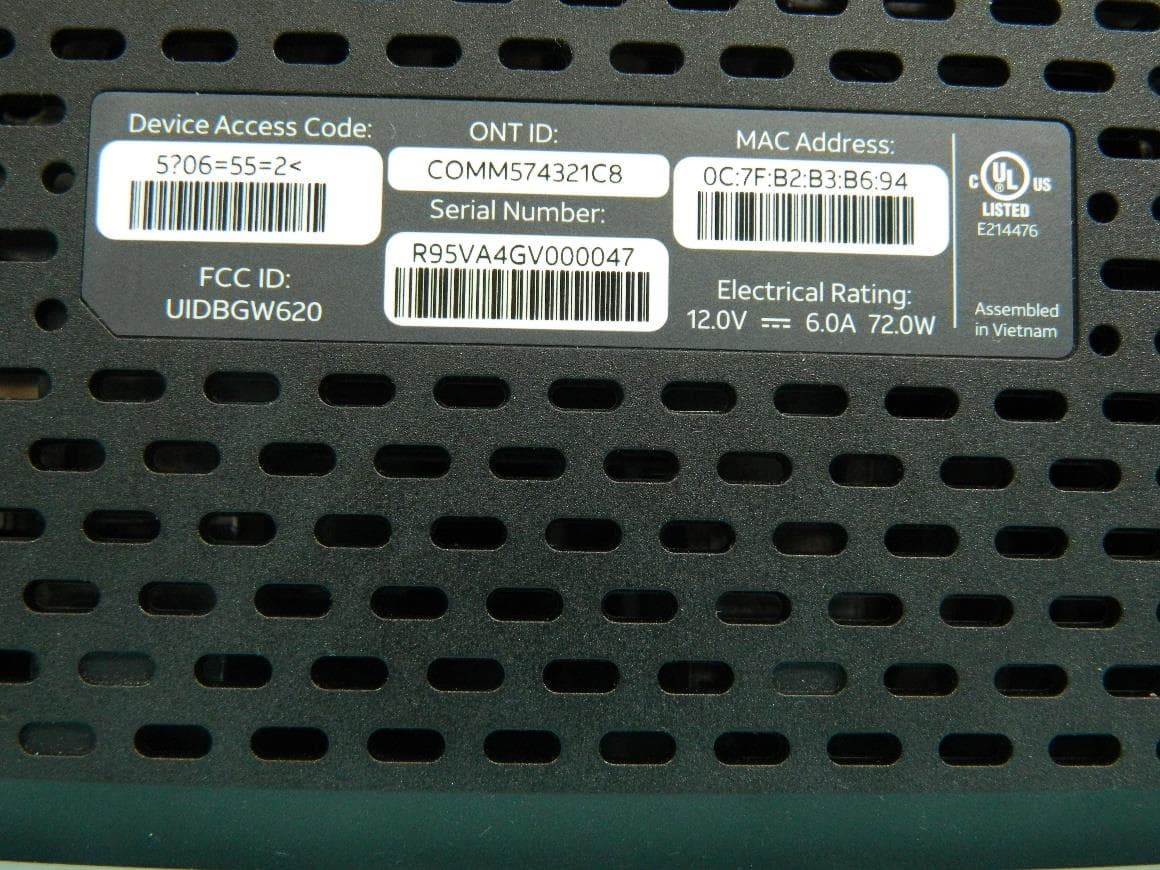
G95BGW620
Aug 26, 2024Wi-Fi 7 XGS-PON Gateway
Equipment Class
NII - Unlicensed National Information Infrastructure TX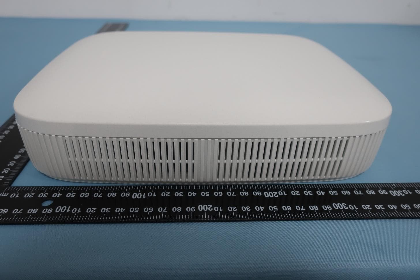
G954981X2
Jan 10, 2024DOCSIS 3.1
Equipment Class
NII - Unlicensed National Information Infrastructure TXG95OWA7111
Jul 20, 2023Wi-Fi 6E Extender
Equipment Class
6PP - 15E 6 GHz Subordinate Indoor Device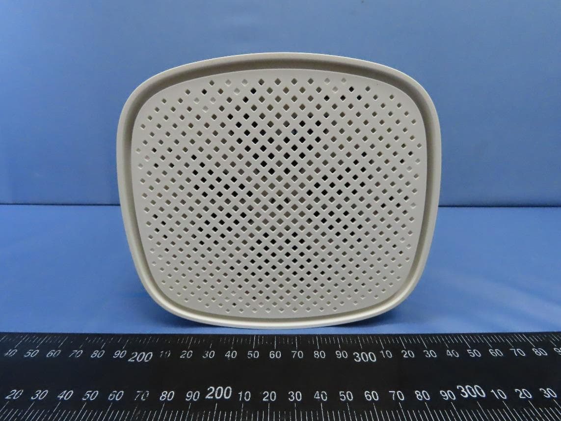
G95EWM322T
Jul 17, 2023Wireless Access Point
Equipment Class
DTS - Digital Transmission System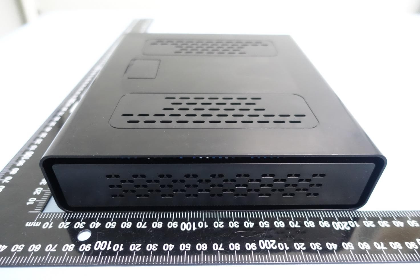
G95-CGA437T
Jan 14, 2023DOCSIS 3.1 Residential Voice Gateway
Equipment Class
NII - Unlicensed National Information Infrastructure TX