G95EWM322TWireless Access Point
Vantiva USA LLC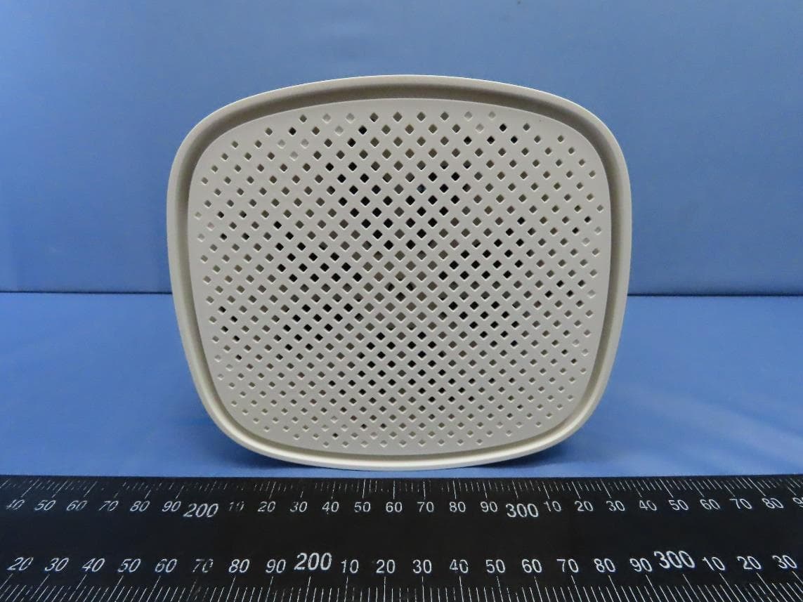
Click to zoom
Application Details
- Equipment Class
- DTS - Digital Transmission System
- Date of Grant
- Jul 17, 2023
- Application Purpose
- Original Equipment
- Date of Application
- Jul 03, 2023
- Equipment Note
- Wireless Access Point
- Frequency Range
- 2405.00000000 - 2480.00000000
- Company
- Vantiva USA LLC
- Country
- United States
Documents & Files
Document Text
Text extracted from the exhibit documents filed with the FCC. Open a document above to read the original.
Users Manual
1 1. Before you start Carefully read the Safety Instructions and Regulatory Notices document included in your package before continuing with the installation of your Ethernet gateway. 2. Check the content of your package Your package contains the following items: Item Description A One EWx322T Ethernet gateway B User Documentation (this Quick Setup Guide, Safety Instructions & Regulatory Notices...). Other additional documents may be included. C One power adapter (type may differ depending on region) D One white Ethernet cable (with yellow connectors) 2 3. Model information I/O of EWx322T is shown in below picture. Item Description DC-in PSU Plug in. Reset Recessed button to push. Refer 7.2 for How-to. ETH port 4 1G LAN port in yellow; 1 2.5G WAN port in RED. USB One USB 2.0 port. 4. Connect your Ethernet gateway to the Broadband service Choose your installation method To connect your Ethernet gateway to the Internet you can: • Place your Ethernet gateway behind another Internet access device. In this setup your Ethernet gateway is used as local Ethernet gateway. Follow the instructions from “Connect as local Ethernet gateway” below. 3 Connect as local Ethernet gateway 1 Plug the Ethernet cable with the red connectors into the red Ethernet WAN port on your gateway. 2 Plug the other end of the Ethernet cable into the Ethernet port of your Internet access device. 4 4. Power on your Ethernet gateway Plug the connector of the electric power supply adapter into the power inlet port of your Ethernet gateway. Plug the adapter into a nearby power outlet. 5. Connect your network devices We recommend you to first connect one computer/tablet (if possible via a wired connection), then complete the rest of the procedure and as a final step connect the other devices. 5 5.1. Connect your wired (Ethernet) devices If you want to connect a device using a wired (Ethernet) connection: 1 Take the white Ethernet cable. 2 Connect one end of the Ethernet cable to one of the yellow Ethernet ports of your Ethernet gateway. 3 Connect the other end of the Ethernet cable to your device. 4 Connect your other Ethernet devices. 5 We recommend you to first configure your Ethernet gateway (see “6. Configure your Ethernet gateway to your needs (optional)” on page 5) before connecting your Wi‑Fi devices (see 5.2. Connect your Wi‑Fi devices” on page 4). 5.2. Connect your Wi‑Fi devices Your Ethernet gateway has two Wi‑Fi access points: • The 5 GHz access point offers superior transfer rates, is less sensitive to interference and allows you to connect Wi‑Fi 6E (IEEE802.11a/n/ac/ax) devices that support 5 GHz. 6 • The 2.4 GHz access point allows you to connect Wi‑Fi 6E (IEEE802.11b/g/n/ac/ax) devices. Use this access point for Wi‑Fi devices that don’t support 5 GHz. Your Ethernet gateway supports band steering, a function that lets your Ethernet gateway automatically select the best access point for each of your connected Wi‑Fi devices. If band steering is enabled both access points will appear as one. Wi‑Fi settings label The label of your Ethernet gateway provides useful information about your Wi‑Fi network. Which is accessible through scanning of QRcode on label: • The Network Name. This name is used to identify your Wi‑Fi network. Some use the term SSID instead. • The Wireless Key. This key is used to secure your Wi‑Fi network. Only devices that use this key can connect to the Wi‑Fi network. You can enter this key manually or configure it automatically using WPS. If band steering is disabled, each access point will have its own Network Name and Wireless Key. Tips To achieve optimal link quality: • Always try to reduce the number of obstacles (especially walls) between your Wi‑Fi devices to a minimum. • Do not place your Wi‑Fi devices in the neighbourhood of devices that cause interference (microwave ovens, cordless phones, baby monitors, etc.). Connecting a Wi‑Fi device using WPS Push Button Configuration (PBC) 1 Make sure that your Wi‑Fi devices supports WPS PBC and you know how to start it. For more information, consult the documentation of your Wi‑Fi device. 2 On your Ethernet gateway, briefly press the WPS () button and release it. 7 The WPS ( ) LED starts blinking blue slowly. 3 Within two minutes, start WPS PBC on your Wi‑Fi device. You will probably have to do this in one of the following ways: Press a WPS ( ) button on your Wi‑Fi device. Start WPS (PBC) on the user interface of your Wi‑Fi device. Open a list of available networks and select the Network Name mentioned on the label of your gateway. 4 After a few seconds, your Wi‑Fi device should be connected. If the WPS ( ) LED starts blinking fast, then your Ethernet gateway could not connect your Wi‑Fi device. For more information, see “The WPS LED is blinking fast” on page 6. Connecting a Wi‑Fi device manually On your Wi‑Fi device, proceed as follows: 1 Open the list of available Wi‑Fi networks and select the entry that contains the Network Name from the label. 2 Your Wi‑Fi device will ask you to enter the Wi‑Fi key or password. 6. Configure your Ethernet gateway to your needs (optional) The Ethernet gateway web interface allows you to configure your Ethernet gateway using your web browser. To access the gateway web user interface: 1 Browse to http://192.168.1.1 on a computer or device that is currently connected to your Ethernet gateway (either wired or over Wi‑Fi). 2 The Ethernet gateway web interface appears. By default, you are logged in as guest. This means that some items are hidden. To view all items, click Sign In and enter admin as user name and the ACCESS KEY printed on the label of your Ethernet gateway as password. 8 7. Troubleshooting 7.1. WPS troubleshooting WPS does not start Make sure that the Wi‑Fi is on. You can check the Ethernet gateway web interface. See “6. Configure your Ethernet gateway to your needs (optional)” on page 5 for more information. The WPS LED is blinking fast This indicates that your Ethernet gateway could not connect to …
Text truncated - open the document above for the full version.
Users Manual
EWx322T Guide d'installation rapide 1 1. Avant de commencer Lisez attentivement le document Instructions de sécurité et avis réglementaires inclus dans votre emballage avant de poursuivre l'installation de votre passerelle Ethernet. 2. Vérifier le contenu de votre emballage Votre emballage contient les éléments suivants : Élément Description A Une passerelle Ethernet EWx322T B Documentation utilisateur (le présent Guide d'installation rapide, les Instructions de sécurité et avis réglementaires...). D'autres documents supplémentaires peuvent être inclus. C Un adaptateur secteur (le type peut varier selon la région) D Un câble Ethernet blanc (avec connecteurs jaunes) 2 3. Informations sur le modèle Les E/S de l'EWx322T sont illustrées sur l'image ci-dessous. Élément Description Entrée CC Fiche du bloc d'alimentation. Réinitialiser Bouton encastré à enfoncer. Reportez-vous au 7.2 pour savoir comment procéder. Port ETH 4 ports LAN 1G en jaune ; 1 port WAN 2.5G en ROUGE. USB Un port USB 2.0. 4. Connecter votre passerelle Ethernet au service Haut Débit Choisissez votre méthode d'installation Pour connecter votre passerelle Ethernet à Internet, vous pouvez : • Placer votre passerelle Ethernet derrière un autre périphérique d'accès à Internet. Dans cette configuration, votre passerelle Ethernet est utilisée en tant que passerelle Ethernet locale. Suivez les instructions de « Connecter en tant que passerelle Ethernet locale » ci-dessous. 3 Connecter en tant que passerelle Ethernet locale 1 Branchez le câble Ethernet avec les connecteurs rouges sur la prise port Ethernet rouge WAN de votre passerelle. 2 Branchez l'autre extrémité du câble Ethernet sur le port Ethernet de votre périphérique d’accès à Internet. 4 4. Allumer votre passerelle Ethernet Branchez le connecteur de l'adaptateur secteur sur le port d'entrée d'alimentation de votre passerelle Ethernet. Branchez l'adaptateur sur une prise de courant à proximité. 5. Connecter vos périphériques réseau Nous vous recommandons de connecter d'abord un ordinateur/tablette (si possible via une connexion filaire), puis de réaliser le reste de la procédure et en dernier lieu de connecter les autres appareils. 5 5.1. Connecter vos appareils filaires (Ethernet) Si vous souhaitez connecter un appareil à l'aide d'une connexion filaire (Ethernet) : 1 Prenez le câble Ethernet blanc. 2 Connectez une extrémité du câble Ethernet à l'un des ports Ethernet jaunes de votre passerelle Ethernet. 3 Branchez l'autre extrémité du câble Ethernet sur votre appareil. 4 Connectez vos autres appareils Ethernet. 5 Nous vous recommandons de configurer d'abord votre passerelle Ethernet (voir « 6. Configurez votre passerelle Ethernet selon vos besoins (facultatif) » à la page 8) avant de connecter vos appareils Wi-Fi (voir 5.2. Connecter vos appareils Wi-Fi » à la page 5). 5.2. Connecter vos appareils Wi-Fi Votre passerelle Ethernet dispose de deux points d'accès Wi-Fi : • Le Point d'accès 5 GHz offre des taux de transfert supérieurs, est moins sensible aux interférences et vous permet de connecter des appareils Wi-Fi 6E (IEEE802.11a/n/ac/ax) prenant en charge 5 GHz. 6 • Le Point d'accès 2,4 GHz vous permet de connecter des appareils Wi-Fi 6E (IEEE802.11b/g/n/ac/ax). Utilisez ce point d'accès pour les appareils Wi-Fi qui ne prennent pas en charge le 5 GHz. Votre passerelle Ethernet prend en charge le pilotage de bande, fonction qui permet à votre passerelle Ethernet de sélectionner automatiquement le meilleur point d'accès pour chacun de vos appareils Wi-Fi connectés. Si le pilotage de bande est activé, les deux points d'accès apparaissent comme un seul. Étiquette des paramètres Wi-Fi L'étiquette de votre passerelle Ethernet fournit des informations utiles sur votre réseau Wi-Fi. Qui est accessible en scannant le QRcode sur l'étiquette : • Le Nom du réseau. Ce nom est utilisé pour identifier votre réseau Wi-Fi. Certains utilisent le terme SSID à la place. • La Clé sans fil. Cette clé est utilisée pour sécuriser votre réseau Wi-Fi. Seuls les appareils qui utilisent cette clé peuvent se connecter au réseau Wi-Fi. Vous pouvez saisir cette clé manuellement ou la configurer automatiquement à l'aide de WPS. Si le pilotage de bande est désactivé, chaque point d'accès a son propre nom de réseau et sa propre clé sans fil. Conseils Pour obtenir une qualité de liaison optimale : • Essayez toujours de réduire au minimum le nombre d'obstacles (en particulier les murs) entre vos appareils Wi-Fi. • Ne placez pas vos appareils Wi-Fi à proximité d'appareils qui provoquent des interférences (fours à micro-ondes, téléphones sans fil, babyphones, etc.). 7 Connexion d'un appareil Wi-Fi à l'aide de la configuration par bouton-poussoir WPS (PBC) 1 Assurez-vous que vos appareils Wi-Fi prennent en charge la PBC WPS et que vous savez comment la démarrer. Pour plus d'informations, consultez la documentation de votre appareil Wi-Fi. 2 Sur votre passerelle Ethernet, appuyez brièvement sur le bouton WPS () et relâchez-le. La LED WPS () commence à clignoter lentement en bleu. 3 Dans les deux minutes, démarrez la PBC WPS sur votre appareil Wi-Fi. Vous devrez probablement le faire de l'une des façons suivantes : Appuyer sur un bouton WPS () sur votre appareil Wi-Fi. Démarrer WPS (PBC) sur l'interface utilisateur de votre appareil Wi-Fi. Ouvrir une liste des réseaux disponibles et sélectionner le Nom de réseau mentionné sur l'étiquette de votre passerelle. 4 Après quelques secondes, votre appareil Wi-Fi devrait être connecté. Si la LED WPS () commence à clignoter rapidement, cela signifie que votre passerelle Ethernet n'a pas pu connecter votre appareil Wi-Fi. Pour plus d'informations, consultez « Le voyant WPS clignote rapidement » à la page 6. Connexion d'un appareil Wi-Fi manuellement sur votre appareil Wi-Fi, procédez comme suit : 1 Ouvrez la liste des réseaux Wi-Fi disponibles et sélectionnez l'entrée contenant le Nom de réseau de l'étiquette. 2 Votre appareil Wi-Fi vous demande de saisir la clé ou l…
Text truncated - open the document above for the full version.
Cover Letter(s)
Page 1 vantiva.com 30 -May-2023
External Photos
Reference No.: CGJR-WTW-P23010147 Page 1/6 CONSTRUCTION PHOTOS OF EUT Reference No.: CGJR-WTW-P23010147 Page 2/6 Reference No.: CGJR-WTW-P23010147 Page 3/6 Reference No.: CGJR-WTW-P23010147 Page 4/6 Reference No.: CGJR-WTW-P23010147 Page 5/6 Reference No.: CGJR-WTW-P23010147 Page 6/6
Internal Photos
Reference No.: CGJR-WTW-P23010147 Page 1/34 CONSTRUCTION PHOTOS OF EUT Reference No.: CGJR-WTW-P23010147 Page 2/34 Reference No.: CGJR-WTW-P23010147 Page 3/34 Reference No.: CGJR-WTW-P23010147 Page 4/34 Reference No.: CGJR-WTW-P23010147 Page 5/34 Reference No.: CGJR-WTW-P23010147 Page 6/34 Reference No.: CGJR-WTW-P23010147 Page 7/34 Reference No.: CGJR-WTW-P23010147 Page 8/34 Reference No.: CGJR-WTW-P23010147 Page 9/34 Reference No.: CGJR-WTW-P23010147 Page 10/34 Reference No.: CGJR-WTW-P23010147 Page 11/34 Reference No.: CGJR-WTW-P23010147 Page 12/34 Reference No.: CGJR-WTW-P23010147 Page 13/34 Reference No.: CGJR-WTW-P23010147 Page 14/34 Reference No.: CGJR-WTW-P23010147 Page 15/34 Reference No.: CGJR-WTW-P23010147 Page 16/34 Reference No.: CGJR-WTW-P23010147 Page 17/34 Reference No.: CGJR-WTW-P23010147 Page 18/34 Reference No.: CGJR-WTW-P23010147 Page 19/34 Reference No.: CGJR-WTW-P23010147 Page 20/34 Reference No.: CGJR-WTW-P23010147 Page 21/34 Reference No.: CGJR-WTW-P23010147 Page 22/34
Internal Photos
Reference No.: CGJR-WTW-P23010147 Page 23/34 6G1 Antenna Reference No.: CGJR-WTW-P23010147 Page 24/34 6G2 Antenna Reference No.: CGJR-WTW-P23010147 Page 25/34 Reference No.: CGJR-WTW-P23010147 Page 26/34 6G3 Antenna Reference No.: CGJR-WTW-P23010147 Page 27/34 6G4 Antenna Reference No.: CGJR-WTW-P23010147 Page 28/34 Reference No.: CGJR-WTW-P23010147 Page 29/34 DB1 Antenna Reference No.: CGJR-WTW-P23010147 Page 30/34 DB2 Antenna Reference No.: CGJR-WTW-P23010147 Page 31/34 Reference No.: CGJR-WTW-P23010147 Page 32/34 DB3 Antenna Reference No.: CGJR-WTW-P23010147 Page 33/34 DB4 Antenna Reference No.: CGJR-WTW-P23010147 Page 34/34
RF Exposure Info
Report No.: MFCGJR-WTW-P23010147 Page No. 1 / 14 Report Format Version: 7.1.0 RF EXPOSURE REPORT CERTIFICATE OF CONFORMITY FCC Rule Part: FCC Part 2 (Section 2.1091) Report No.: MFCGJR-WTW-P23010147 FCC ID: G95EWM322T Product: Wireless Access Point Brand: technicolor Test Model: EWM322TTCH2 Variant Model: EGM322TTCH2 Received Date: 2023/2/13 Test Date: 2023/3/16 Issued Date: 2023/5/17 Applicant: Vantiva USA LLC Address: 4855 Peachtree Industrial Blvd. Suite 200 Norcross, Georgia 30092. Issued By: Bureau Veritas Consumer Products Services (H.K.) Ltd., Taoyuan Branch Lin Kou Laboratories Lab Address: No. 47-2, 14th Ling, Chia Pau Vil., Lin Kou Dist., New Taipei City, Taiwan Test Location: No. 19, Hwa Ya 2nd Rd., Wen Hwa Vil., Kewi Shan Dist., Taoyuan City 33383, Taiwan FCC Registration / Designation Number: 788550 / TW0003 Approved by: , Date: 2023/5/17 Jeremy Lin / Project Engineer This test report consists of 14 pages in total. It may be duplicated completely for legal use with the approval of the applicant. It should not be reproduced except in full, without the written approval of our laboratory. The test results in the report only apply to the tested sample. The test results in this report are traceable to the national or international standards. Prepared by : Vera Huang / Specialist This report is governed by, and incorporates by reference, the Conditions of Testing as posted at the date of issuance of this report at http://www.bureauveritas.com/home/about-us/our- business/cps/about-us/terms-conditions/ and is intended for your exclusive use. Any copying or replication of this report to or for any other person or entity, or use of our name or trademark, is permitted only with our prior written permission. This report sets forth our findings solely with respect to the test samples identified herein. The results set forth in this report are not indicative or representative of the quality or characteristics of the lot from which a test sample was taken or any similar or identical product unless specifically and expressly noted. Our report includes all of the tests requested by you and the results thereof based upon the information that you provided to us. Measurement uncertainty is only provided upon request for accredited tests. Statements of conformity are based on simple acceptance criteria without taking measurement uncertainty into account, unless otherwise requested in writing. You have 60 days from date of issuance of this report to notify us of any material error or omission caused by our negligence or if you require measurement uncertainty; provided, however, that such notice shall be in writing and shall specifically address the issue you wish to raise. A failure to raise such issue within the prescribed time shall constitute your unqualified acceptance of the completeness of this report, the tests conducted and the correctness of the report contents. Report No.: MFCGJR-WTW-P23010147 Page No. 2 / 14 Report Format Version: 7.1.0 Table of Contents Release Control Record ....................................................................................................................................................... 3 1 Certificate .................................................................................................................................................................... 4 2 Measurement Uncertainty ......................................................................................................................................... 5 3 Applicable RF Exposure Limit .................................................................................................................................. 6 3.1 RF Exposure ............................................................................................................................................................. 9 4 Test Results .............................................................................................................................................................. 10 4.1 RF Exposure ........................................................................................................................................................... 10 5 Conclusion ................................................................................................................................................................ 13 6 Information of the Testing Laboratories ................................................................................................................ 14 Report No.: MFCGJR-WTW-P23010147 Page No. 3 / 14 Report Format Version: 7.1.0 Release Control Record Issue No. Description Date Issued MFCGJR-WTW-P23010147 Original Release 2023/5/17 Report No.: MFCGJR-WTW-P23010147 Page No. 4 / 14 Report Format Version: 7.1.0 1 Certificate Product: Wireless Access Point Brand: technicolor Test Model: EWM322TTCH2 Variant Model: EGM322TTCH2 Sample Status: Engineering sample Applicant: Vantiva USA LLC Test Date: 2023/3/16 FCC Rule Part: FCC Part 2 (Section 2.1091) Standard: KDB 447498 D04 Interim General RF Exposure Guidance v01 The above equipment has been tested by Bureau Veritas Consumer Products Services (H.K.) Ltd., Taoyuan Branch, and found compliance with the requirement of the above standards. The test record, data evaluation & Equipment Under Test (EUT) configurations represented herein are true and accurate accounts of the measurements of the sample’s RF characteristics under the conditions specified in this report. Report No.: MFCGJR-WTW-P23010147 Page No. 5 / 14 Report Format Version: 7.1.0 2 Measurement Uncertainty Where relevant, the following measurement uncertainty levels have been estimated for tests performed on the EUT. Measurement Specification Expanded Uncertainty (k=2) (±) RF Exposure 1 GHz ~ 2.5 GHz 1.2 dB 2.5 GHz ~ 8 GHz 1.3 dB Report No.: MFCGJR-WTW-P23010147 Page No. 6 / 14 Report Format Version: 7.1.0 3 Applicable RF Exposure Limit § 1.1310 Radiofrequency r…
Text truncated - open the document above for the full version.
Test Report
EWM322T/EWA322T –ANTENNA 2023-06-20 v6 2 DUT Model EWM322T/EWA322T Manufacturer Technicolor Connected Home USA LLC 4855 Peachtree Industrial Blvd. Suite 200 Norcross, Georgia 30092. WLAN2G5G6G ChipsetBCM6715BCM6715BCM6715 MIMO4x44x44x4 Interfacewl2wl1wl0 BW20/40MHz20/40/80/160MHz20/40/80/160MHz Frequencies (20MHz channels central frequencies) 2412MHz - 2462MHz 5180MHz - 5825MHz 5955MHz - 7115MHz 2G –5G chipsets RF connectors The Photo Please refer to Antenna Test Photo 6G chipset RF connectors The Photo Please refer to Antenna Test Photo Antenna DB12.4/5GHz6322922AANTENNA PCB antenna Off-board DUAL BAND 2.4/5.0 GHZ W COAX CABLE 82MM BLUE MODULE DB1 EWA322TGFR2 DB22.4/5GHz6322923AANTENNA PCB antenna Off-board DUAL BAND 2.4/5.0 GHZ W COAX CABLE 111MM GREY MODULE DB2 EWA322TGFR2 DB32.4/5GHz6322924AANTENNA PCB antenna Off-board DUAL BAND 2.4/5.0 GHZ W COAX CABLE 145MM WHITE MODULE DB3 EWA322TGFR2 DB42.4/5GHz6322925AANTENNA PCB antenna Off-board DUAL BAND 2.4/5.0 GHZ W COAX CABLE 129MM BLACK MODULE DB4 EWA322TGFR2 6G16GHz6322927AANTENNA PCB antenna Off-board 6GHZ W COAX CABLE 68MM BLUE MODULE 6G1 EWA322TGFR2 6G26GHz6322928AANTENNA PCB antenna Off-board 6GHZ W COAX CABLE 85MM WHITE MODULE 6G2 EWA322TGFR2 6G36GHz6322929AANTENNA PCB antenna Off-board 6GHZ W COAX CABLE 70MM BLACK MODULE 6G3 EWA322TGFR2 6G46GHz6322930AANTENNA PCB antenna Off-board 6GHZ W COAX CABLE 98MM GREY MODULE 6G4 EWA322TGFR2 Wi-Fi AntennaFrequency bandIPN Decription All antennas are fabricated by LUXSHARE-ICT (Address:No.158 JinchangRoad, JinxiTown, Suzhou, Jiangsu province, China) 6 Dual-band 2,4/5GHz antenna 7 6GHz antenna 8 Antenna test environment for the dual-band antennas •The dual-band antennas are tested in a full anechoic chamber (MVG/SG24) with the VNA Keysight/ E5071C Satimo SG24 name of commercial test software spm1.3.1 and satenv 2.0.1.5 build12 DeviceType/ModeSerialManufacturerCal. DateCal. due Date SG24StandardSG24MVG11/15/202111/14/2022 Turn TableN/A-MVGN/AN/A Power Supply UnitCASTLE 3K(6G) 190916- 26590068SANTAKN/AN/A Active Switching UnitN/A MODU-009-A- 0120MVGN/AN/A Control Unit SG24N/A MODU-022-A- 0032MVGN/AN/A Amplification UnitN/A MODU-020-B- 0005MVGN/AN/A Cable 8m -400MHz to 6GHzSUCOFLEX 106SN 81469 /6MVG11/15/202111/14/2022 Temperature & Humiditydeli-deliN/AN/A ENA Series Network AnalyzerE5071CMY46523087KeySight11/24/202111/23/2022 The Photo Please refer to Antenna Test Photo 9 Antenna test environment for the 6GHz antennas •The 6GHz antennas are tested in a full anechoic chamber (EMT-RCR120) with the VNA Keysight/ N5225B EMT-RCR120 Compact Antenna Test Range(CATR) name of commercial test software EMT Far-Field Antenna Measurement System DeviceType/ModeSerialManufacturerCal.DateCal.Due Date EMT-RCR120StandardEMT-RCR120EM-Testing10/26/202110/25/2022 Three-dimensional rotary table and its control systemDongtintechDT001201911104EM-TestingN/AN/A PNA Network AnalyzerN5225BMY58422424KeySight6/23/20226/23/2023 Reflective surface system RCR120 -EM-TestingN/AN/A Feeders and their control systemsEMT4000-EM-TestingN/AN/A Power Supply UnitCASTLE 3K(6G)190929-35470033SANTAKN/AN/A Cable 4m -5GHz to 50GHzJB360-Jun You10/26/202110/25/2022 Temperature & Humiditydeli-deliN/AN/A The Photo Please refer to Antenna Test Photo 10 Antenna test setup •Antennas are tested after a full calibration of the chamber (including the testing cable insertion loss) •Antenna are tested in LUXSHARE-ICT (Address:No.158 JinchangRoad, JinxiTown, Suzhou, Jiangsu province, China) •Antennas are tested by Xucheng. Hu ([email protected]) •Antennas are tested in 2022/08/02 The Photo Please refer to Antenna Test Photo 11 Test procedure The very common “gain comparison” method is used to measure the antenna gain in full anechoic chamber which contains the receiving and transmitting antennas The method requires an antenna which gain is exactly known (called gain standard). Two measurements are performed in receiving mode in the whole sphere in both vertical and horizontal polarizations: the reference antenna is first measured, providing the received power P0 and secondly the test antenna, providing the received power PAUT both antennas are placed exactly in the same arrangement. Then the formulae below are applied to calculate the gain: Where: GAUTis the gain of the test antenna GGSis the gain of the gain standard G0is the gain of the transmitting antenna R is the distance between the receiving and transmitting antennas l is the wavelength 12 Antenna gain pattern @2,4GHz Horizontal planeVertical plane (right/left)Vertical plane (front/back) 13 Antenna gain pattern @5,49GHz Horizontal planeVertical plane (right/left)Vertical plane (front/back) 14 Antenna gain pattern @6,295GHz Horizontal planeVertical plane (right/left)Vertical plane (front/back) 15 Antennae gains 6GHz antenna Gain (dBi) Frequency (MHz)5925594560556175629564256475652566156695677568756955699570357125 6G15,525,615,425,195,835,315,145,174,944,94,784,555,345,485,185,14 6G24,154,164,624,825,155,384,854,425,014,865,645,454,624,554,935,51 6G35,685,634,944,695,345,565,484,944,445,214,495,765,225,054,935,09 6G45,575,725,356,085,676,2766,155,785,856,165,794,844,784,875,23 Dual band antenna Gain (dBi) Frequency (MHz)2400-2483.5517052505330549056005730573558155835 DB13,925,614,914,885,345,455,075,165,285,47 DB23,495,965,655,775,655,915,535,244,794,8 DB34,184,214,214,134,714,814,84,634,244,11 DB44,523,963,514,182,754,063,613,683,863,75 16 BLE Antenna The BLE antenna is printed on the Wi-Fi board and is PIFA (printed inverted F antenna) type The Photo Please refer to Antenna Test Photo 17 BLE antenna: Gain and radiation pattern Frequency (MHz)Gain (dBi) 24013.44 24423.95 24832.93 Horizontal planeVertical plane (right/left) Vertical plane (front/back) 18 versions 2022-09-01 v1: Initial release. Arnaud Goblet. 2023-02-03 v2: added BLE antenna, radiation patterns, product and manufacturer information. AG 2023-06-07 v3: Add information on test environment and setup (page 8-10) 2023-06…
Text truncated - open the document above for the full version.
Test Report
Report No.: RFCGJR-WTW-P23010147-4 Page No. 1 / 17 Report Format Version:6.1.2 Multi-Antenna Systems Directional Gain measurement Report No.: RFCGJR-WTW-P23010147-4 FCC ID: G95EWM322T Test Model: EWM322TTCH2 Variant Model: EGM322TTCH2 Received Date: Feb. 13, 2023 Test Date: Feb. 08 ~ Mar. 28, 2023 Issued Date: May 17, 2023 Applicant: Vantiva USA LLC Address: 4855 Peachtree Industrial Blvd. Suite 200 Norcross, Georgia 30092. Issued By: Bureau Veritas Consumer Products Services (H.K.) Ltd., Taoyuan Branch Lin Kou Laboratories Lab Address: No. 47-2, 14th Ling, Chia Pau Vil., Lin Kou Dist., New Taipei City, Taiwan Test Location: No. 19, Hwa Ya 2nd Rd., Wen Hwa Vil., Kwei Shan Dist., Taoyuan City 33383, Taiwan FCC Registration / Designation Number: 788550 / TW0003 This report is governed by, and incorporates by reference, the Conditions of Testing as posted at the date of issuance of this report at http://www.bureauveritas.com/home/about-us/our-business/cps/about-us/terms-conditions/ and is intended for your exclusive use. Any copying or replication of this report to or for any other person or entity, or use of our name or trademark, is permitted only with our prior written permission. This report sets forth our findings solely with respect to the test samples identified herein. The results set forth in this report are not indicative or representative of the quality or characteristics of the lot from which a test sample was taken or any similar or identical product unless specifically and expressly noted. Our report includes all of the tests requested by you and the results thereof based upon the information that you provided to us. Measurement uncertainty is only provided upon request for accredited tests. Statements of conformity are based on simple acceptance criteria without taking measurement uncertainty into account, unless otherwise requested in writing. You have 60 days from date of issuance of this report to notify us of any material error or omission caused by our negligence or if you require measurement uncertainty; provided, however, that such notice shall be in writing and shall specifically address the issue you wish to raise. A failure to raise such issue within the prescribed time shall constitute your unqualified acceptance of the completeness of this report, the tests conducted and the correctness of the report contents. Report No.: RFCGJR-WTW-P23010147-4 Page No. 2 / 17 Report Format Version:6.1.2 Table of Contents Release Control Record .................................................................................................................................... 3 1 EUT Antenna System Description ........................................................................................................ 4 1.1 Antenna Information ............................................................................................................................. 4 1.2 Antenna Location .................................................................................................................................. 5 1.3 EUT Operation mode ............................................................................................................................ 5 2 Conducted Power Measurement .......................................................................................................... 7 2.1 Test Setup ............................................................................................................................................ 7 2.2 Test Instruments .................................................................................................................................. 7 2.3 Test Procedure .................................................................................................................................... 7 2.4 Test Results of RF Conducted Power ................................................................................................... 7 3 3D Antenna Pattern Measurement and Directional gain calculation (Mea…
Text truncated - open the document above for the full version.
Contact Information
Applicant
Robert Lyall(Principal Certification Engineer)
Test Firm
Bureau Veritas CPS(H.K.) Ltd., Taoyuan BranchLiu Ken
Technical Specifications
| # | Rule Parts | Frequency Range | Power Output |
|---|---|---|---|
| 3 | 15C | 2.40 GHz - 2.48 GHz | 87.00 mW |
Other Applications from Vantiva USA LLC
G95BGW620
Aug 26, 2024Wi-Fi 7 XGS-PON Gateway
Equipment Class
NII - Unlicensed National Information Infrastructure TX
G954981X2
Jan 10, 2024DOCSIS 3.1
Equipment Class
NII - Unlicensed National Information Infrastructure TXG95OWA7111
Jul 20, 2023Wi-Fi 6E Extender
Equipment Class
6PP - 15E 6 GHz Subordinate Indoor Device
G95-CGA437T
Jan 14, 2023DOCSIS 3.1 Residential Voice Gateway
Equipment Class
NII - Unlicensed National Information Infrastructure TX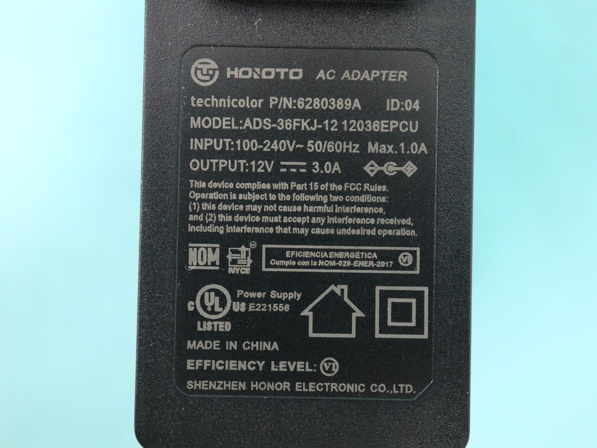
G95-CGA437A
Dec 07, 2022DOCSIS 3.1 Residential Voice Gateway
Equipment Class
NII - Unlicensed National Information Infrastructure TX