G95-TG794US DECT BASE UNIT
Vantiva USA LLC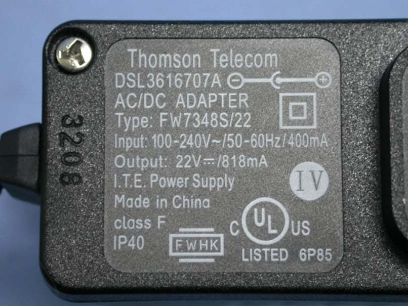
Click to zoom
Application Details
- Equipment Class
- PUB - Part 15 Unlicensed PCS Base Station
- Date of Grant
- Apr 29, 2009
- Application Purpose
- Original Equipment
- Date of Application
- Apr 28, 2009
- Equipment Note
- US DECT BASE UNIT
- Frequency Range
- 1921.53600000 - 1928.44800000
- Company
- Vantiva USA LLC
- Country
- United States
Documents & Files
Document Text
Text extracted from the exhibit documents filed with the FCC. Open a document above to read the original.
Users Manual
DRAFT VERIZON QUICK SETUP GUIDE A detailed User Guide is available at verizonwireless.com/hub © 2009 Verizon. All rights reserved. Box contents You box contains the following items: 1Power Adaptor 2A white Ethernet cable 3A yellow Ethernet cable 4The Hub 5This Quick Setup Guide Connect the Hub to the Bridge Modem Proceed as follows: 1Plug one end of the white Ethernet cable in the Hub’s white WAN port. 2Plug the other end in your Bridge Modem’s Ethernet port. Connect the Hub to the Home Router Proceed as follows: 1Plug one end of the yellow Ethernet cable in the Hub’s white Ethernet port. 2Plug the other end in your Home Router’s Ethernet port. VERIZON QUICK INSTALLATION GUIDE A detailed User Guide is available at verizonwireless.com/hub © 2009 Verizon. All rights reserved. 3 2 1 4 5 WANWANWAN Internet Bridge Modem Connect the Power adapter. Proceed as follows: 1Plug the connector of the electric power adapter into the Hub’s Power port. 2Plug the adapter into a nearby power outlet. Turn on the Hub Push the On/Off button to turn on the Hub. After some time: •The Power LED should be solid green. •The Ethernet LED should be solid/flashing green. •The BroadBand LED should be solid green. If this is not the case, check the connections that you made in the previous steps. Connect the Hub to your Phone The Hub allows you to connect both DECT phones and fixed phones. To connect: •A DECT phone or a fixed phone connected to a D2A device, consult the Setup and User Guide for more information. •A fixed phone, plug the phone cable in the Hub’s Phone port. Read the Safety Instructions and Regulatory Notices Before you start using your Hub, carefully read the Safety Instructions and Regulatory Notices on the following pages. Power Phone Safety Instructions and Regulatory Notices BEFORE YOU START INSTALLATION OR USE OF THIS PRODUCT, CAREFULLY READ THESE INSTRUCTIONS Directive Unless express and prior approval by THOMSON in writing, you may not: •Disassemble, de-compile, reverse engineer, trace or otherwise analyse the equipment, its content, operation, or functionality, or otherwise attempt to derive source code (or the underlying ideas, algorithms, structure or organization) from the equipment, or from any other information provided by THOMSON, except to the extent that this restriction is expressly prohibited by local law; •Copy, rent, loan, re-sell, sub-license, or otherwise transfer or distribute the equipment to others; •Modify, adapt or create a derivative work of the equipment; •Remove from any copies of the equipment any product identification, copyright or other notices; •Disseminate performance information or analysis (including, without limitation, benchmarks) from any source relating to the equipment. Such acts not expressly approved by THOMSON will result in the loss of product warranty and may invalidate the user's authority to operate this equipment in accordance with FCC Rules. THOMSON disclaims all responsibility in the event of use that does not comply with the present instructions. Environmental information - WEEE directive Please help us protect the environment in which we live! Safety Instructions Climatic conditions This product: •Is intended for in-house stationary desktop use; the maximum ambient temperature may not exceed 40°C (104°F). •Must not be mounted in a location exposed to direct or excessive solar and/or heat radiation. •Must not be exposed to heat trap conditions and must not be subjected to water or condensation. •Must be installed in a Pollution Degree 2 environment (Environment where there is no pollution or only dry, nonconductive pollution). Cleaning Unplug this product from the wall socket and computer before cleaning. Do not use liquid cleaners or aerosol cleaners. Use a damp cloth for cleaning. Water and moisture Do not use this product near water, for example, near a bathtub, washbowl, kitchen sink, laundry tub, in a wet basement or near a swimming pool. Transition of the product from a cold environment to a hot one, may cause condensation on some of its internal parts. Allow it to dry by itself before re-starting the product. Interface classifications The external interfaceson the rear panel of the product are classified as follows: •Phone, VoIP, FXS: TNV circuit, not subjected to over voltages (TNV-2) •All other interface ports (e.g. Ethernet, 10/100Base-T/MDI(-X), USB, E1, ATMF-25, Console, Craft, etc.), including the low voltage power input from the AC mains power supply: SELV circuits. ! When using this product, always follow the basic safety precautions to reduce the risk of fire, electric shock and injury to persons, including the following: •Always install the product as described in the documentation that is included with your product. •Avoid using this product during an electrical storm. There may be a remote risk of electric shock from lightning. •Do not use this product to report a gas leak in the vicinity of the leak. This symbol means that your inoperative electronic appliance must be collected separately and not mixed with the household waste.The European Union has implemented a specific collection and recycling system for which poducers' are responsible. This appliance has been designed and manufactured with high quality materials and components that can be recycled and reused. Electrical and electronic appliances are liable to contain parts that are necessary in order for the system to work properly but which can become a health and environmental hazard if they are not handled or disposed of in the proper way. Consequently, please do not throw out your inoperative appliance with the household waste. If you are the owner of the appliance, you must deposit it at the appropriate local collection point or leave it with the vendor when buying a new appliance. •If you are a professional user, please follow your supplier's instructions. •If the appliance is rented to you or left in your care, please contact your service provider. ! WA RNING •The tele…
Text truncated - open the document above for the full version.
External Photos
FCC ID: G95-TG794 ETC Report No.: 09-03-MAS-127 Page A1 of A2 ANNEX A: EXTERNAL CONSTRUCTION PHOTOS OF EUT 1. Outside view 1 of EUT 2. Outside view 2 of EUT FCC ID: G95-TG794 ETC Report No.: 09-03-MAS-127 Page A2 of A2 3. Adapter
ID Label/Location Info
FCC ID Label & Location FCC ID: G95-TG794 FCC ID: G95-TG794
Internal Photos
FCC ID: G95-TG794 ETC Report No.: 09-03-MAS-127 Page B1 of B4 ANNEX B: INTERNAL CONSTRUCTION PHOTOS OF EUT 1. Inside View 1 of EUT 2. Inside View 2 of EUT FCC ID: G95-TG794 ETC Report No.: 09-03-MAS-127 Page B2 of B4 3. Inside View 3 of EUT 4. Inside View 4 of EUT FCC ID: G95-TG794 ETC Report No.: 09-03-MAS-127 Page B3 of B4 5. Front view of PCB 6. Rear view of PCB FCC ID: G95-TG794 ETC Report No.: 09-03-MAS-127 Page B4 of B4 7. Antenna
RF Exposure Info
FCC ID: G95-TG794 Sheet 30 of 92 Sheets ETC Report No.: 09-03-MAS-127 Electronics Testing Center, Taiwan No.8, Lane 29, Wenming RD., LeShan Tsuen, GuiShan Shiang, Taoyuan County 33383, Taiwan, R.O.C. Rev. No 1.0 6.11 Safety exposure levels 6.11.1 Standard Applicable: FCC 15.319(i) UPCS devices are subject to the radio frequency radiation exposure requirements specified in FCC parts 1.1307 (b), 2.1091 and 2.1093, as appropriate. All equipment shall be considered to operate in a “general population / uncontrolled environment. For portable devices tests according to IEEE 1528 are requested, if applicable. 6.11.2 Measurement procedure Consideration of radio frequency radiation exposure for EUT is done as SAR test according IEEE1528 (for PP) MPE calculation as below (for FP, Repeater) SAR test results: not applicable MPE calculation: The EUT is considered as a mobile device according to OET Bulletin 65, Edition -97-01. Therefore distance to human body of min. 20 cm is determined. The limit of Power density for General Population / Umcontrolled Exposure is 1.0 mW/cm². Formula: S = EIRP / 4πR² Calculation: EIRP Radiated Power (dBm) 22.73 EIRP Radiated Power (mW) 187.5 R Distance (cm) 20 S Power Density (mW/cm²)0.04 6.11.3 Results:Complies
Test Report
FCC ID: G95-TG794 Sheet 1 of 92 Sheets ETC Report No.: 09-03-MAS-127 Electronics Testing Center, Taiwan No.8, Lane 29, Wenming RD., LeShan Tsuen, GuiShan Shiang, Taoyuan County 33383, Taiwan, R.O.C. Rev. No 1.0 CONFORMANCE TEST REPORT FOR FCC Part 15, subpart D Report No.: 09-03-MAS-127 Client: Thomson Inc. Product: US DECT PHONE - BASE (FP) Model: DSLCBA794VZ FCC ID: G95-TG794 Manufacturer/supplier: Thomson Inc. Date test item received: 2009/03/17 Date test campaign completed: 2009/03/20 Date of issue: 2009/04/24 The test result only corresponds to the tested sample. It is not permitted to copy this report, in part or in full, without the permission of the test laboratory. Total number of pages of this test report: 92 pages Total number of pages of photos: External photos 2 pages Internal photos 4 pages Setup photos 2 pages Test Engineer Checked By Approved By John Li David You Joe Hsieh FCC ID: G95-TG794 Sheet 2 of 92 Sheets ETC Report No.: 09-03-MAS-127 Electronics Testing Center, Taiwan No.8, Lane 29, Wenming RD., LeShan Tsuen, GuiShan Shiang, Taoyuan County 33383, Taiwan, R.O.C. Rev. No 1.0 Table of Contents Page 1 GENARAL INFORMATION......................................................................................................... 4 1.1 Testing Laboratory..................................................................................................................... 4 1.2 Client Information....................................................................................................................... 4 1.3 Manufacturer...............................................................................................................................4 2 TEST INFORMATION.................................................................................................................. 5 2.1 Description of Tested Device(s)............................................................................................... 5 2.2 Test Environment....................................................................................................................... 5 3 TEST REPORT SUMMARY........................................................................................................ 6 3.1 Test Summary............................................................................................................................ 6 3.2 Other Comments........................................................................................................................ 7 4 TEST SETUP................................................................................................................................. 8 4.1 Frequency and Timing Measurements................................................................................... 8 4.2 Conducted Emission Tests....................................................................................................... 8 4.3 Radiated Emission Tests.......................................................................................................... 9 4.4 Power line Conducted Tests.................................................................................................... 9 4.5 Monitoring Tests....................................................................................................................... 10 5 TEST EQUIPMENT LIST........................................................................................................... 11 6 TEST RESULT............................................................................................................................ 12 6.1 Coordination with fixed microwave........................................................................................ 12 6.2 Cross Reference...................................................................................................................... 13 6.3 Labeling Requirements........................................................................................................... 16 6.4 Power line Conducted Emissions.......................................................................................... 17 6.5 Antenna Requirement............................................................................................................. 20 6.6 Digital Modulation Techniques............................................................................................... 20 6.7 Peak Transmit Power.............................................................................................................. 21 6.8 Power Spectral Density........................................................................................................... 25 6.9 Antenna Gain............................................................................................................................ 29 6.10 Automatic discontinuation of transmission......................................................................... 29 6.11 Safety exposure levels.......................................................................................................... 30 6.12 Emission Bandwidth B.......................................................................................................... 31 6.13 Monitoring time....................................................................................................................... 35 6.14 Monitoring threshold.............................................................................................................. 36 6.15 Maximum transmit period..................................................................................................... 37 FCC ID: G95-TG794 Sheet 3 of 92 Sheets ETC Report No.: 09-03-MAS-127 Electronics Testing Center, Taiwan No.8, Lane 29, Wenming RD., LeShan Tsuen, GuiShan Shiang, Taoyuan County 33383, Taiwan, R.O.C. Rev. No 1.0 6.16 System Acknowledgement................................................................................................... 39 6.17 Least Interfered Cha…
Text truncated - open the document above for the full version.
Test Setup Photos
FCC ID: G95-TG794 ETC Report No.: 09-03-MAS-127 Page 1 of 2 Photos of Radiation Measuring Setup FCC ID: G95-TG794 ETC Report No.: 09-03-MAS-127 Page 2 of 2 Photos of Conduction Measuring Setup
Contact Information
Applicant
Robert Lyall(Principal Certification Engineer)
Test Firm
Electronics Testing Center, TaiwanWinpo Tsai
Technical Specifications
| # | Rule Parts | Frequency Range | Power Output |
|---|---|---|---|
| 1 | 15D | 1.92 GHz - 1.93 GHz | 60.00 mW |
Other Applications from Vantiva USA LLC
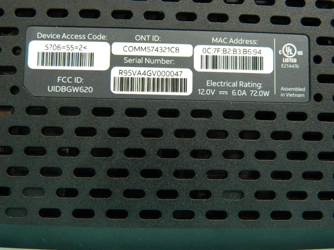
G95BGW620
Aug 26, 2024Wi-Fi 7 XGS-PON Gateway
Equipment Class
NII - Unlicensed National Information Infrastructure TX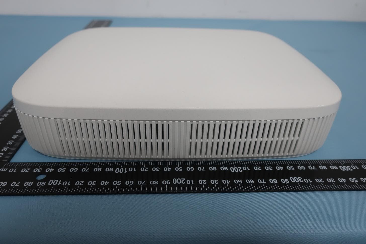
G954981X2
Jan 10, 2024DOCSIS 3.1
Equipment Class
NII - Unlicensed National Information Infrastructure TXG95OWA7111
Jul 20, 2023Wi-Fi 6E Extender
Equipment Class
6PP - 15E 6 GHz Subordinate Indoor Device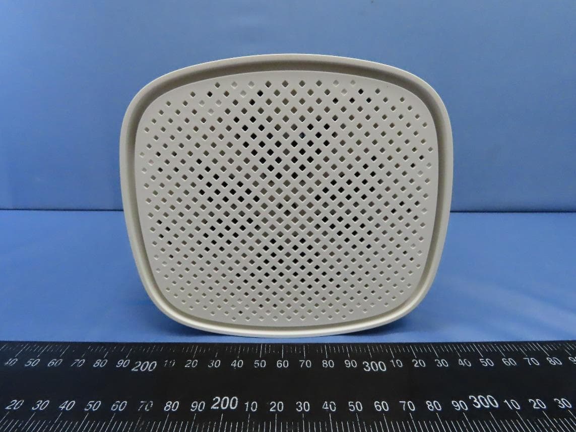
G95EWM322T
Jul 17, 2023Wireless Access Point
Equipment Class
DTS - Digital Transmission System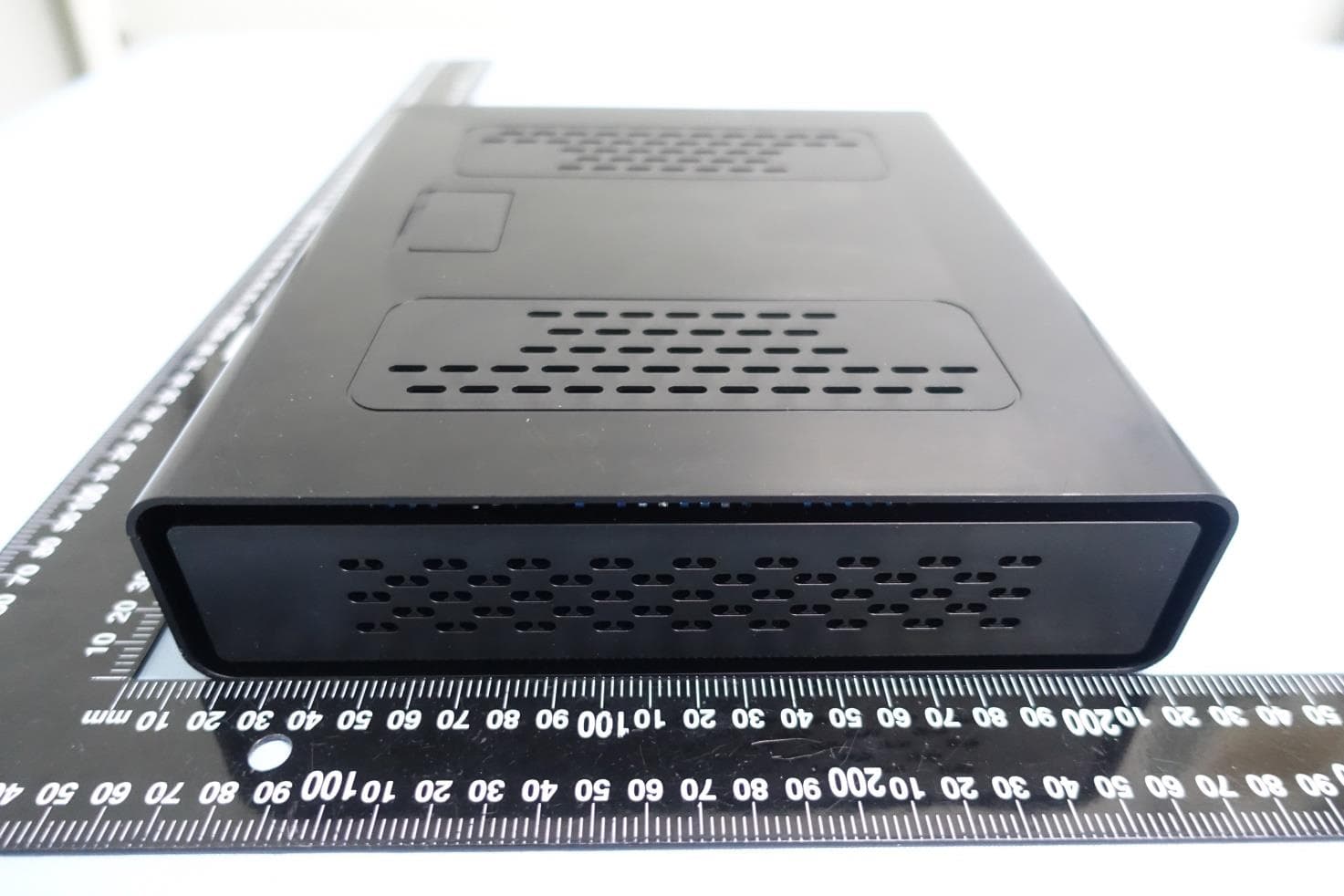
G95-CGA437T
Jan 14, 2023DOCSIS 3.1 Residential Voice Gateway
Equipment Class
NII - Unlicensed National Information Infrastructure TX