G95DCI104COMDigital Transport Adaptor (DTA)
Vantiva USA LLC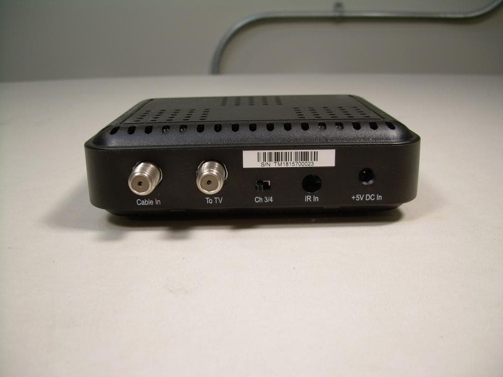
Click to zoom
Application Details
- Equipment Class
- DTS - Digital Transmission System
- Date of Grant
- Jan 11, 2011
- Application Purpose
- Original Equipment
- Date of Application
- Jan 11, 2011
- Equipment Note
- Digital Transport Adaptor (DTA)
- Frequency Range
- 2425.00000000 - 2475.00000000
- Company
- Vantiva USA LLC
- Country
- United States
Documents & Files
Document Text
Text extracted from the exhibit documents filed with the FCC. Open a document above to read the original.
Users Manual
Important Safety Instructions Read these instructions. Keep these instructions. Heed all warnings. Follow all instructions. Do not use this apparatus near water. Clean only with a dry cloth. Do not block any ventilation openings. Install in accordance with the manufacturer’s instructions. Do not install near any heat sources such as radiators, heat registers, stoves, or other apparatus (including amplifiers) that produce heat. Do not defeat the safety purpose of the polarized or grounding-type plug. A polarized plug has two blades with one wider than the other. A grounding- type plug has two blades and a third grounding prong. The wide blade or the third prong is provided for your safety. If the provided plug does not fit into your outlet, consult an electrician for replacement of the obsolete outlet. Protect the power cord from being walked on or pinched particularly at plugs, convenience receptacles, and at the point where they exit from the apparatus. Only use attachments/accessories specified by the manufacturer. Unplug the apparatus during lightning storms or when unused for long periods of time. Refer all servicing to qualified service personnel. Servicing is required when the apparatus has been damaged in any way, such as power-supply cord or plug is damaged, liquid has been spilled or objects have fallen into the apparatus, the apparatus has been exposed to rain or moisture, does not operate normally, or has been dropped. If an outside antenna or cable system is connected to the product, be sure the antenna or cable system is grounded so as to provide some protection against voltage surges and built-up static charges. Ensuring Optimum Performance Disconnect the product from the power before you connect the product to (or disconnect it from) any other equipment. Avoid any contact with the power, which can be lethal or cause severe electric shock. Do not insert anything into any opening of the case. Leave the power socket accessible so that you can unplug the set quickly. Leave 2 to 3 inches around the product to ensure proper ventilation to it. To clean the product, use a dry clean cloth with no cleaning solvent or abrasive products. Clean the ventilation openings regularly. 3671035E TIS purse5 11/4/11 2:20 PM FCC Information The User is cautioned that changes or modifications, not expressly approved by the party responsible for compliance, could void the user’s ability to operate the equipment. This equipment has been tested and found to comply with the limits for a Class B digital device, pursuant to part 15 of the FCC Rules. These limits are designed to provide reasonable protection against harmful interference in a residential installation. This equipment generates, uses and can radiate radio frequency energy and, if not installed and used in accordance with the instructions, may cause harmful interference to radio communications. However, there is no guarantee that interference will not occur in a particular installation. If this equipment does cause harmful interference to radio or television reception, which can be determined by turning the equipment off and on, the user is encouraged to try to correct the interference by one or more of the following measures: • Reorient or relocate the receiving antenna. • Increase the separation between the equipment and receiver. • Connect the equipment into an outlet on a circuit different from that to which the receiver is connected. • Consult the dealer or an experienced radio/TV technician for help. FCC Compliance Statement This device complies with part 15 of the FCC rules. Operation is subject to the following 2 conditions: 1. This device may not cause harmful interference; 2. This device must accept any interference received, including interference that may cause undesired operation. Responsible party (contact for FCC matter only): Technicolor Inc. 101 W. 103rd St. Indianapolis, IN 46290 U.S.A. Meaning of Symbols This symbol is intended to alert the user to the presence of uninsulated “dangerous voltage” within the product housing that may be of sufficient magnitude to constitute a risk of shock. This symbol is intended to alert the user to the presence of important operating and maintenance (servicing) instructions accompanying the product. Model TypeDCI104XXX Operating Voltage120V AC / 60 Hz / 0.5A Typical Power Consumption6W max. Weight0.35 lb. / 0.16 kg Dimensions (W x H x D)4.92 x 1.38 x 3.94 Inches Operating Temperature Range59 to 95ºF / 15 to 35ºC Storage Temperature Range- 4 to 158ºF / -20 to 70ºC Environmental Information The batteries use some hazardous substances which pollute the environment. Do not dispose of them with other articles. Take care to dispose of them at special collecting points. Technical Specifications 3671035E Manufactured under license from Dolby Laboratories. 3671035E TIS purse5 21/4/11 2:20 PM
External Photos
Front View of the DCI104COM Back View of the DCI104COM Chassis
Internal Photos
View of the component Side of the PCB View of the Trace Side of the PBC
Test Report
Nemko-CCL, Inc. 1940 West Alexander Street Salt Lake City, UT 84119 801-972-6146 Test Report Certification Test Of: DCI104XXX FCC ID: G95DCI104COM Test Specification: FCC PART 15, Subpart C Test Report Serial No: 2572 Applicant: Technicolor 101 West 103 rd Street Indianapolis, IN 46290-1102 Date of Test: February 11 & 15, 2010 Issue Date: March 16, 2010 Accredited Testing Laboratory By: NVLAP Lab Code 100272-0 Nemko-CCL, Inc. TEST REPORT: 2572 FCC ID#: G95DCI104COM Page 2 of 40 2 CERTIFICATION OF ENGINEERING REPORT This report has been prepared by Nemko-CCL, Inc. to document compliance of the device described below with the requirements of Federal Communications Commission (FCC) Part 15, Subpart C. This report may be reproduced in full, partial reproduction may only be made with the written consent of the laboratory. The results in this report apply only to the sample tested. - Applicant: Technicolor - Manufacturer: Technicolor - Brand Name: Comcast - Model Number: DCI104XXX - FCC ID Number: G95DCI104COM On this 16 th day of March 2010, I, individually, and for Nemko-CCL, Inc., certify that the statements made in this engineering report are true, complete, and correct to the best of my knowledge, and are made in good faith. Although NVLAP has recognized that the Nemko-CCL, Inc. EMC testing facilities are in good standing, this report must not be used to claim product certification, approval, or endorsement by NVLAP, NIST, or any agency of the federal government. Nemko-CCL, Inc. Tested by: Norman P. Hansen EMC Technician Nemko-CCL, Inc. TEST REPORT: 2572 FCC ID#: G95DCI104COM Page 3 of 40 3 TABLE OF CONTENTS PAGE SECTION 1.0 CLIENT INFORMATION .................................................................................4 SECTION 2.0 EQUIPMENT UNDER TEST (EUT) .................................................................5 SECTION 3.0 TEST SPECIFICATION, METHODS & PROCEDURES .............................8 SECTION 4.0 OPERATION OF EUT DURING TESTING ..................................................14 SECTION 5.0 SUMMARY OF TEST RESULTS ...................................................................15 SECTION 6.0 MEASUREMENTS, EXAMINATIONS AND DERIVED RESULTS ..........16 APPENDIX 1 TEST PROCEDURES AND TEST EQUIPMENT ..........................................27 APPENDIX 2 PHOTOGRAPHS ................................................................................................31 Nemko-CCL, Inc. TEST REPORT: 2572 FCC ID#: G95DCI104COM Page 4 of 40 4 SECTION 1.0 CLIENT INFORMATION 1.1 Applicant: Company Name: Technicolor. 101 West 103 rd Street Indianapolis, IN 46290-1102 Contact Name: Nancy Boettner Title: Manager, Product Safety & Compliance 1.2 Manufacturer: Company Name: Technicolor 101 West 103 rd Street Indianapolis, IN 46290-1102 Contact Name: Nancy Boettner Title: Manager, Product Safety & Compliance Nemko-CCL, Inc. TEST REPORT: 2572 FCC ID#: G95DCI104COM Page 5 of 40 5 SECTION 2.0 EQUIPMENT UNDER TEST (EUT) 2.1 Identification of EUT: Brand Name: Comcast Model Number: DCI104XXX Serial Number: TM1815700023 2.2 Description of EUT: The DCI104XXX is wirelessly controlled digital to analog video converter box. The DCI104XXX has a Cable in port, To TV port, and DC power port. The DCI104XXX has a 2.4 GHz transceiver for interfacing the remote control unit. The DCI104XXX has 2 traces on the PCB used as antennas. Each antenna has its own transmit path from the transceiver chip. Only one transmit or receive path is active at any given time. The DCI104XXX was tested with signals output to each antenna. The DCI104XXX was tested while powered by a Technicolor DCI1011Com (Friwo) power supply and a Technicolor DCI105COM (AC Bel WA9003) power supply. This report shows the data from testing that had the least margin when compared to the limit. The 2.4 GHz transceiver operates using 3 channels and was tested at each of the 3 frequencies. Channel Frequency (MHz) Channel Frequency (MHz) Channel Frequency (MHz) 1 2425 2 2450 3 2475 This report covers the circuitry of the devices subject to FCC Part 15, Subpart C. The circuitry of the device subject to FCC Part 15, Subpart B has been tested and is covered in Nemko-CCL, Inc. report 2571. 2.3 EUT and Support Equipment: The FCC ID numbers for all the EUT and support equipment used during the test are listed below: Nemko-CCL, Inc. TEST REPORT: 2572 FCC ID#: G95DCI104COM Page 6 of 40 6 Brand Name Model Number FCC ID Number Description Name of Interface Ports / Interface Cables BN: Technicolor MN: DCI104XXX (Note 1) G95DCI104COM Converter Box with Transceiver See Section 2.4 BN: Sony MN: DLV-S19A10 DoC Television RF In/RG6 coax cable with F-type connectors (Note 2) BN: Dell MN: Latitude D620 DoC Computer Docking port/Direct connection to docking station BN: Dell MN: PD01X DoC Docking Station RF Out/ RG6 coax cable with F-type connectors (Note 2) Note: (1) EUT (2) Interface port connected to EUT (See Section 2.4) The support equipment listed above was not modified in order to achieve compliance with this standard. 2.4 Interface Ports on EUT: Name of Ports No. of Ports Fitted to EUT Cable Descriptions/Length Cable In 1 RG6 coax cable with F-type connectors/5 meters To TV 1 RG6 coax cable with F-type connectors/1.5 meters DC In 1 Unshielded DC power cord from power supply/1.5 meters Nemko-CCL, Inc. TEST REPORT: 2572 FCC ID#: G95DCI104COM Page 7 of 40 7 2.5 Modification Incorporated/Special Accessories on EUT: There were no modifications or special accessories required to comply with the specification. Signature: Typed Name: Nancy Boettner Title: Manager, Product Safety & Compliance Nemko-CCL, Inc. TEST REPORT: 2572 FCC ID#: G95DCI104COM Page 8 of 40 8 SECTION 3.0 TEST SPECIFICATION, METHODS & PROCEDURES 3.1 Test Specification: Title: FCC PART 15, Subpart C (47 CFR 15) 15.203, 15.207, and 15.247 Limits and methods of measurement of radio interference characteristics of radio frequency devices Purpose of Test: The tests were performed to demonstrate init…
Text truncated - open the document above for the full version.
Test Setup Photos
Front View Radiated Test Setup – Worst-Case Configuration Back View Radiated Test Setup – Worst-Case Configuration Front View Conducted Disturbance Configuration Back View Conducted Disturbance Configuration
Contact Information
Applicant
Robert Lyall(Principal Certification Engineer)
Test Firm
VPI TechnologyJason Stewart
[email protected]801-495-2310
Technical Specifications
| # | Rule Parts | Frequency Range | Power Output |
|---|---|---|---|
| 1 | 15C | 2.42 GHz - 2.48 GHz | 134.00 µW |
Other Applications from Vantiva USA LLC
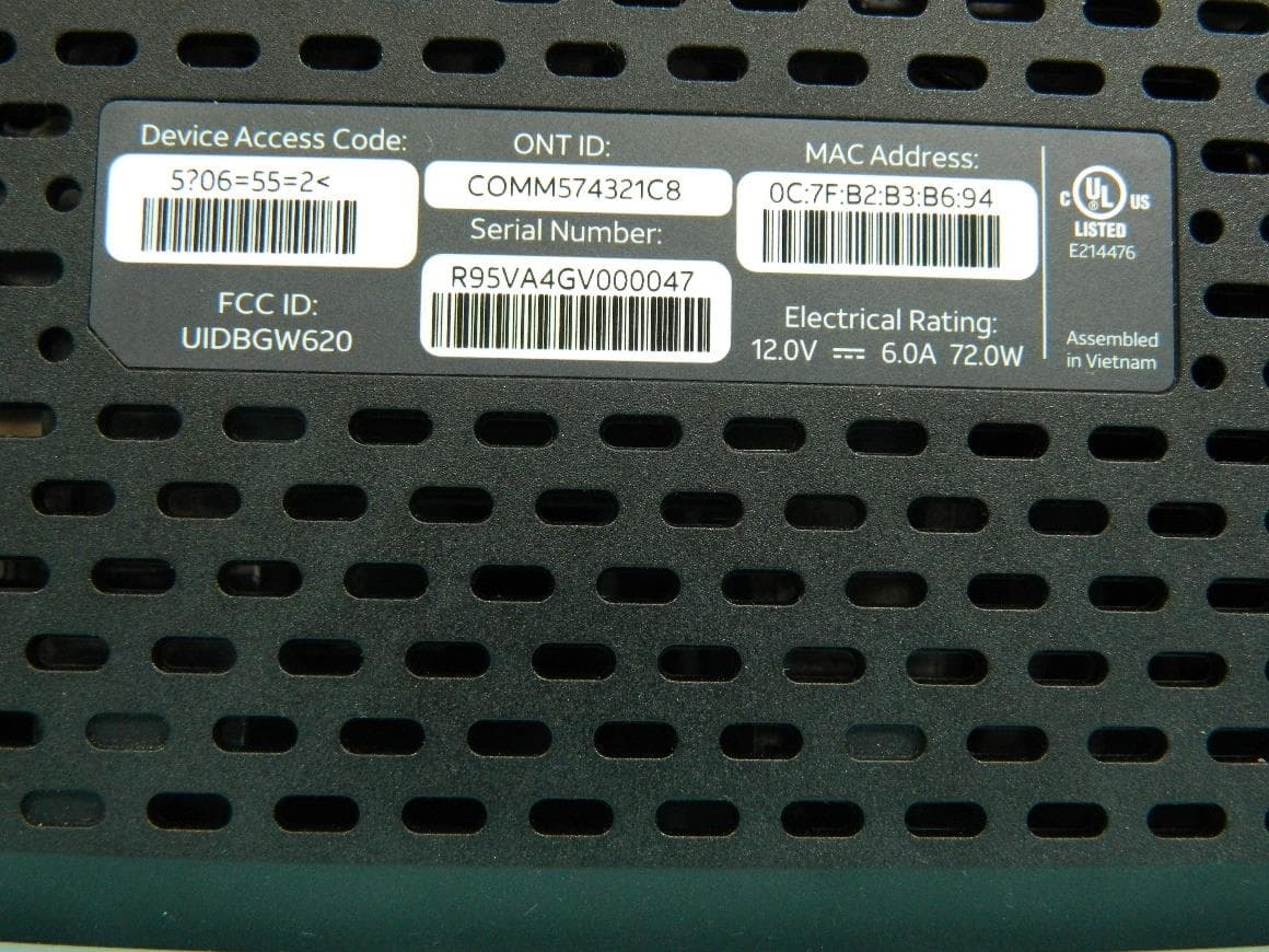
G95BGW620
Aug 26, 2024Wi-Fi 7 XGS-PON Gateway
Equipment Class
NII - Unlicensed National Information Infrastructure TX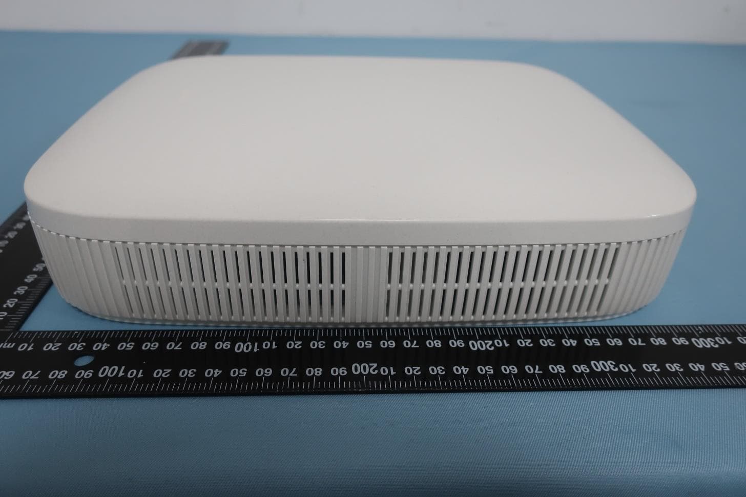
G954981X2
Jan 10, 2024DOCSIS 3.1
Equipment Class
NII - Unlicensed National Information Infrastructure TXG95OWA7111
Jul 20, 2023Wi-Fi 6E Extender
Equipment Class
6PP - 15E 6 GHz Subordinate Indoor Device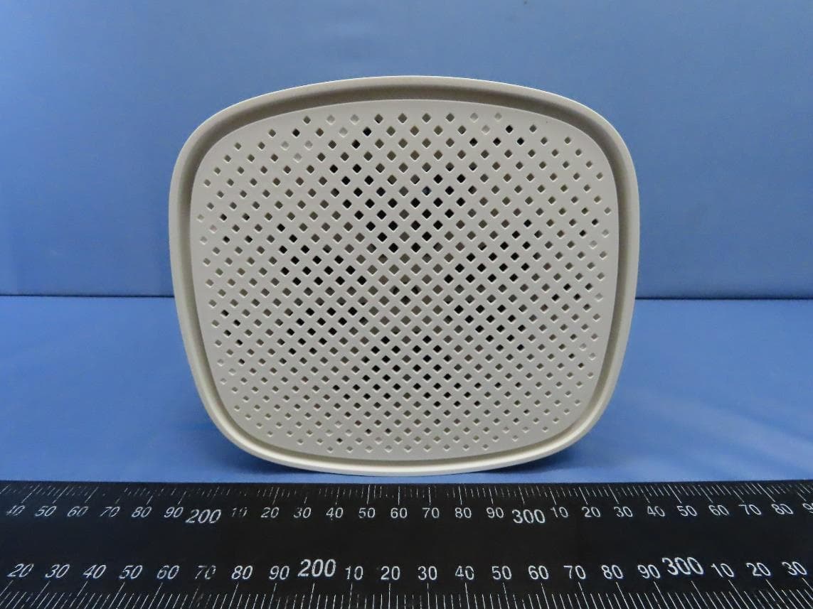
G95EWM322T
Jul 17, 2023Wireless Access Point
Equipment Class
DTS - Digital Transmission System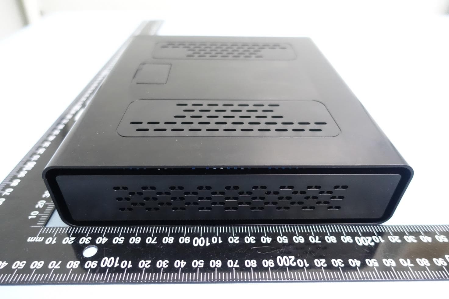
G95-CGA437T
Jan 14, 2023DOCSIS 3.1 Residential Voice Gateway
Equipment Class
NII - Unlicensed National Information Infrastructure TX