G95DCI401GEU2wirelessly controlled converter box
Vantiva USA LLC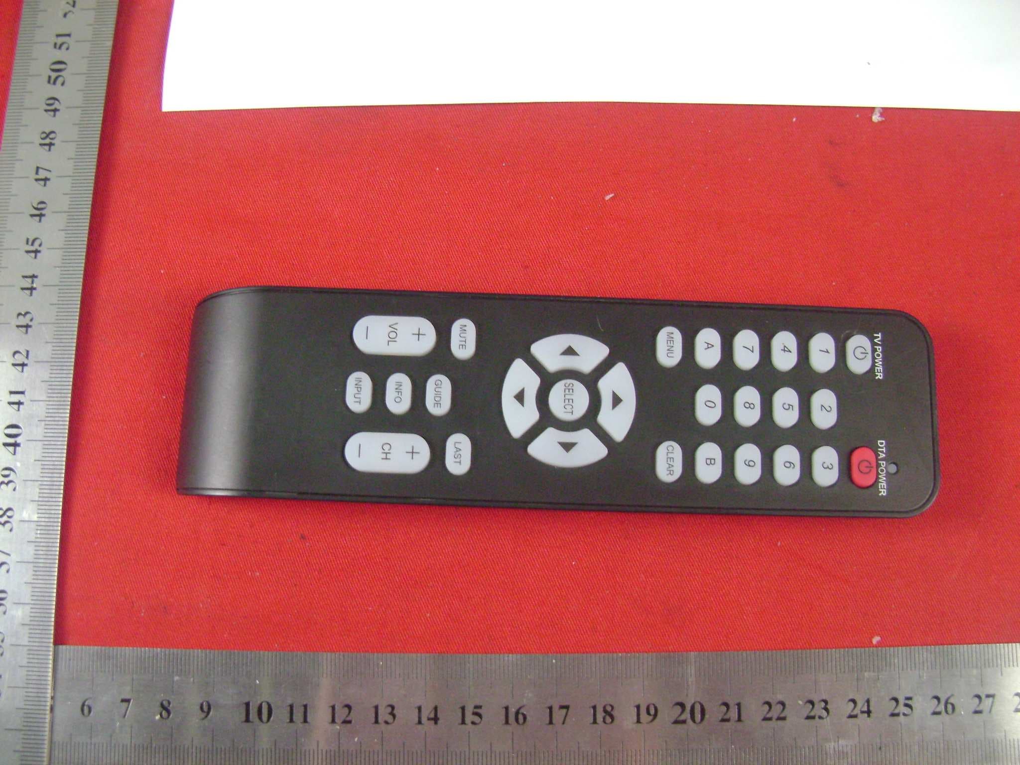
Click to zoom
Application Details
- Equipment Class
- HID - Part 15 TV Interface Device
- Date of Grant
- Jul 19, 2011
- Application Purpose
- Original Equipment
- Date of Application
- Jul 19, 2011
- Equipment Note
- wirelessly controlled converter box
- Frequency Range
- 61.25000000 - 71.75000000
- Company
- Vantiva USA LLC
- Country
- United States
Documents & Files
Document Text
Text extracted from the exhibit documents filed with the FCC. Open a document above to read the original.
Users Manual
HD-DTA Easy Setup Guide Installation • Operation • Troubleshooting C25M75Y50KCYGB5075M25YK25CMYGB7550CGB25M50Y25KCMP75C50MY75K 2 Table of Contents What’s included in this Install Kit? 4 Start Here! 6 Connecting to a TV with HDMI Cable (No VCR) 8 Connecting to a TV+VCR with Coax cable 9 Connecting to a TV with Coax cable (No VCR) 10 Power Up 12 Connecting to the Network and activating your HD-DTA 14 Verify your Services 15 Programming the new remote 16 HD-DTA Operation Guide 20 Using your HD-DTA and VCR 21 Remote Operation Guide 23 RF Remote Pairing Process 26 Troubleshooting Guide 28 DTA Operation Guide (Two remotes) 30 C25M75Y50KCYGB5075M25YK25CMYGB7550CGB25M50Y25KCMP75C50MY75K 3 What you need to know To bring you better service now and in the future your cable operator is upgrading to an All-Digital network – All-Digital for every channel, on every TV set. To continue to receive all the channels you are used to, you will need to make sure that every TV in your home is equipped with one of our HD-DTA or Digital Cable Boxes. What you need to do C25M75Y50KCYGB5075M25YK25CMYGB7550CGB25M50Y25KCMP75C50MY75K 4 What’s included in this Install Kit? HD-DTA Each TV will need to be connected to a HD-DTA or a Digital Cable Box, but not both. HDMI Cable 5 Foot Coax Cable Power Cord Remote Control In order to operate the HD-DTA you must use the remote control included with this kit. Programming instructions for the remote control are included in this guide. 2 AAA Batteries Adhesive Fasteners Use these if you want to stick the HD-DTA to your TV. Note: Please be careful. Technicolor is not responsible for any damage done to any surface you stick these to. C25M75Y50KCYGB5075M25YK25CMYGB7550CGB25M50Y25KCMP75C50MY75K 5 Items that you may also need: Flashlight Power Strip You’ll need a power strip if you already have 2 items plugged into the electrical outlet that you plan to use. Extension Cord You’ll need an extension cord if you already have 2 items plugged into the electrical outlet closest to your TV. C25M75Y50KCYGB5075M25YK25CMYGB7550CGB25M50Y25KCMP75C50MY75K 6 Please refer to the Welcome Letter that was delivered with this kit to identify: Start Here! • The phone number associated with your Cable Operator account • The channel where you can view a video demonstration of these instructions C25M75Y50KCYGB5075M25YK25CMYGB7550CGB25M50Y25KCMP75C50MY75K 7 The last four digits of the serial number of each HD-DTA that you will be activating: Serial Number Location in your home Output Channel Note: The serial number can be found on the bottom of the HD-DTA itself and is also printed on the outside of the HD-DTA package. C25M75Y50KCYGB5075M25YK25CMYGB7550CGB25M50Y25KCMP75C50MY75K 8 A Turn off your TV. B Locate the cable that currently runs from the cable wall outlet to the back of your TV. Leave one end of the cable connected to the wall, but disconnect the other end from the back of your TV. C Reconnect this end of the cable to the “Cable In” input on the back of the HD-DTA. Cable Outlet Wall B TV If you have a VCR, follow the directions on page 9. If you do not have a VCR, follow the directions on this page. Connecting to a TV with HDMI Cable (No VCR) A Find the HDMI cable included in this kit. Connect one end of the cable to the “HDMI” input on the back of the HD-DTA. B Connect the other end to the “HDMI” input on the back of your TV. Connect the HD-DTA to the Cable Outlet Connect the HD-DTA to the TV 1 2 Wall Cable Outlet C A B TV C25M75Y50KCYGB5075M25YK25CMYGB7550CGB25M50Y25KCMP75C50MY75K 9 If you do not have a VCR, follow the directions on page 8. If you have a VCR, follow the directions on this page. Connecting to a TV+VCR with Coax cable A Find the 5-foot coax cable included in this kit. Connect one end of the cable to the “To TV” input on the back of the HD-DTA. B Connect the other end to the “Cable In/ RF In” input on the back of your VCR. A Turn off your TV. B Locate the cable that currently runs from the cable wall outlet to the back of your VCR (or other recording device). Leave one end of the cable connected to the wall, but disconnect the other end from the back of your VCR. C Reconnect this end of the cable to the “Cable In” input on the back of the HD-DTA. Cable Outlet Wall B VCR Connect the HD-DTA to the Cable Outlet Connect the HD-DTA to the VCR 12 Wall Cable Outlet C A B VCR Input C25M75Y50KCYGB5075M25YK25CMYGB7550CGB25M50Y25KCMP75C50MY75K 10 If you have a VCR, follow the directions on this page 9. Connecting to a TV with Coax cable (No VCR) A Find the 5-foot coax cable included in this kit. Connect one end of the cable to the “To TV” input on the back of the HD-DTA. B Connect the other end to the “Cable In/ RF In” input on the back of your TV. A Turn off your TV. B Locate the cable that currently runs from the cable wall outlet to the back of your VCR (or other recording device). Leave one end of the cable connected to the wall, but disconnect the other end from the back of your VCR. C Reconnect this end of the cable to the “Cable In” input on the back of the HD-DTA. Cable Outlet Wall B VCR Wall Cable Outlet C A B Cable IN / RF IN Connect the HD-DTA to the Cable Outlet Connect the HD-DTA to the TV 1 2 C25M75Y50KCYGB5075M25YK25CMYGB7550CGB25M50Y25KCMP75C50MY75K 11 C25M75Y50KCYGB5075M25YK25CMYGB7550CGB25M50Y25KCMP75C50MY75K 12 A If you are connecting the HD-DTA to a television with HDMI, set your TV to choose “HDMI” as the input source. Or Pick which output channel your TV will use and make sure your television is set to that selected channel by setting the switch on the back of the HD-DTA to the proper output channel (Ch 3 or Ch 4). Power Up A B B Find the power cord included in the kit. Plug the end of the power cord into the power input “+ 5V DC In” on the back of the HD-DTA. C25M75Y50KCYGB5075M25YK25CMYGB7550CGB25M50Y25KCMP75C50MY75K 13 C Plug the other end into a working electrical outlet or power strip. Make sure that the outlet is not controlled by a switch that gets turned on and of…
Text truncated - open the document above for the full version.
Users Manual
Important Safety Instructions Read these instructions. Keep these instructions. Heed all warnings. Follow all instructions. Do not use this apparatus near water. Clean only with dry cloth. Do not block any ventilation openings. Install in accordance with the manufacturer’s instructions. Do not install near any heat sources such as radiators, heat registers, stoves, or other apparatus (including amplifiers) that produce heat. Do not defeat the safety purpose of the polarized or grounding-type plug. A polarized plug has two blades with one wider than the other. A grounding type plug has two blades and a third grounding prong. The wide blade or the third prong are provided for your safety. If the provided plug does not fit into your outlet, consult an electrician for replacement of the obsolete outlet. Protect the power cord from being walked on or pinched particularly at plugs, convenience receptacles, and the point where they exit from the apparatus. Only use attachments/accessories specified by the manufacturer. Unplug this apparatus during lightning storms or when unused for long periods of time. Refer all servicing to qualified service personnel. Servicing is required when the apparatus has been damaged in any way, such as power-supply cord or plug is damaged, liquid has been spilled or objects have fallen into the apparatus, the apparatus has been exposed to rain or moisture, does not operate normally, or has been dropped. If an outside antenna or cable system is connected to the product, be sure the antenna or cable system is grounded so as to provide some protection against voltage surges and built-up static charges. To reduce the risk of fire or electric shock, do not expose this apparatus to rain or moisture. Batteries (battery pack or batteries installed) shall not be exposed to excessive heat such as sunshine, fire or the like. Warning: Use only the power supply that came with your unit. If the power supply needs to be replaced, contact your service operator or dealer to obtain an authorized replacement. Changes or modifications not expressly approved by the party responsible for compliance could void the user's authority to operate the equipment. NOTE This equipment has been tested and found to comply with the limits for a Class B digital device, pursuant to part 15 of the FCC Rules. These limits are designed to provide reasonable protection against harmful interference in a residential installation. 2 This equipment generates, uses and can radiate radio frequency energy and, if not installed and used in accordance with the instructions, may cause harmful interference to radio communications. However, there is no guarantee that interference will not occur in a particular installation. If this equipment does cause harmful interference to radio or television reception, which can be determined by turning the equipment off and on, the user is encouraged to try to correct the interference by one or more of the following measures: —Reorient or relocate the receiving antenna. —Increase the separation between the equipment and receiver. —Connect the equipment into an outlet on a circuit different from that to which the receiver is connected. —Consult the dealer or an experienced radio/TV technician for help. Ensuring optimum performance Disconnect the product from the power before you connect the product to (or disconnect it from) any other equipment. Avoid any contact with the power, which can be lethal or cause severe electric shock. Do not insert anything into any opening of the case. Leave the power socket accessible so that you can unplug the set quickly. Leave 2 to 3 inches around the product to ensure proper ventilation to it. To clean the product, use a dry clean soft cloth with no cleaning solvent or abrasive products. Clean the ventilation openings regularly. Environmental information The batteries use some hazardous substances which pollute the environment. Do not dispose of them with other articles. Take care to dispose them at special collecting points. Technical specifications Model type DCI401xxxx Operating voltage 120V AC / 60 Hz / 0.5A Typical Power consumption 5.0W (typical)max 6.0W (max) Weight 0.42 Lb Dimensions (W x H x D) 4.33 x 0.96 x 3.19 Inches Operating temperature range 59 to 104° F / 15 to 40°C Storage temperature range -4 to 158°F / -20 to 70°C Manufactured under license from Dolby Laboratories. 3 ! FCC Compliance Statement This device complies with part 15 of the FCC Rules. Operation is subject to the following two conditions: (1) This device may not cause harmful interference, and (2) this device must accept any interference received, including interference that may cause undesired operation. This device is intended to be attached to a receiver that is not used to receive over-the-air broadcast signals. Connection of this device in any other fashion may cause harmful interference to radio communications and is in violation of the FCC Rules, part 15. FCC & IC Radiation Exposure Statement This equipment complies with FCC radiation exposure limits set forth for an uncontrolled environment and meets the exemption from the routine evaluation limits in section 2.5 of RSS 102. Responsible party (contact for FCC matter only): Technicolor USA, Inc. 101 W. 103rd St. Indianapolis, IN 46290 U.S.A. Tel: 866-670-4844 This device complies with Industry Canada licence-exempt RSS standard(s).Operation is subject to the following two conditions: (1) this device may not cause interference, and (2) this device must accept any interference, including interference that may cause undesired operation of the device. Le présent appareil est conforme aux CNR d'Industrie Canada applicables aux appareils radio exempts de licence. L'exploitation est autorisée aux deux conditions suivantes : (1) l'appareil ne doit pas produire de brouillage, et (2) l'utilisateur de l'appareil doit accepter tout brouillage radioélectrique subi, même …
Text truncated - open the document above for the full version.
External Photos
EXTERNAL POTO DOCUMENTATION 16800650 001,16800650 002 for DCI401GEU2 Technicolor USA, Inc. This documentation consists of 4 pages (excluding this cover page). Photo Documentation Report Number: 16800650 001,1680650 002 Model: DCI401GEU2 - Page 1of 4 - Pic1: Top view of DCI401GEU2 Pic2: Bottom view of DCI401GEU2 Photo Documentation Report Number: 16800650 001,1680650 002 Model: DCI401GEU2 - Page 2of 4 - Pic3: Front view of DCI401GEU2 Pic4: Rear view of DCI401GEU2 Photo Documentation Report Number: 16800650 001,1680650 002 Model: DCI401GEU2 - Page 3of 4 - Pic5: Left of DCI401GEU2 Pic6: Right of DCI401GEU2 Photo Documentation Report Number: 16800650 001,1680650 002 Model: DCI401GEU2 - Page 4of 4 - Pic7: AC adapter of DCI401GEU2 Pic8: Remote control of DCI401GEU2
ID Label/Location Info
For DCI401GEU2: Label size: 23*9mm Label vendor: KK ENTERPRISE (KUNSHAN) CO.,LTD. Label material: White polyester synthetic film Label thickness: 0.05+/- 0.005mm Label adhesive base: ACRYLIC
Internal Photos
INTERNAL POTO DOCUMENTATION 16800650 001,16800650 002 for DCI401GEU2 Technicolor USA, Inc. This documentation consists of 3 pages (excluding this cover page). Photo Documentation Report Number: 16800650 001,16800650 002 Model: DCI401GEU2 - Page 1of 3 - Pic1: Overview (1) of DCI401GEU2 Pic2: Overview (2) of DCI401GEU2 Photo Documentation Report Number: 16800650 001,16800650 002 Model: DCI401GEU2 - Page 2of 3 - Pic3: Shielding component of DCI401GEU2 Pic4: PCB component side (with shielding) of DCI401GEU2 Photo Documentation Report Number: 16800650 001,16800650 002 Model: DCI401GEU2 - Page 3of 3 - Pic5: PCB component side (without shielding) of DCI401GEU2 Pic6: PCB trace side of DCI401GEU2
Test Setup Photos
Photograph 1: Set-up for Conducted Emissions Photograph 2: Set-up for Radiated Emissions, 30MHz-1GHz Photograph 3: Set-up for Radiated Emissions 1GHz – 2GHz
Contact Information
Applicant
Robert Lyall(Principal Certification Engineer)
Technical Contact
TUV Rheinland (China) Ltd.Kai Yang
[email protected]010-65666660
Unit 707, AVIC Bldg. No.10B,Central Road, East 3rd · Beijing · China
Test Firm
The State Radio_Monitoring_Center Testing (SRTC)Junfeng Wang
Technical Specifications
| # | Rule Parts | Frequency Range | Power Output |
|---|---|---|---|
| 1 | 15B | 61.25 MHz - 71.75 MHz | - |
Other Applications from Vantiva USA LLC
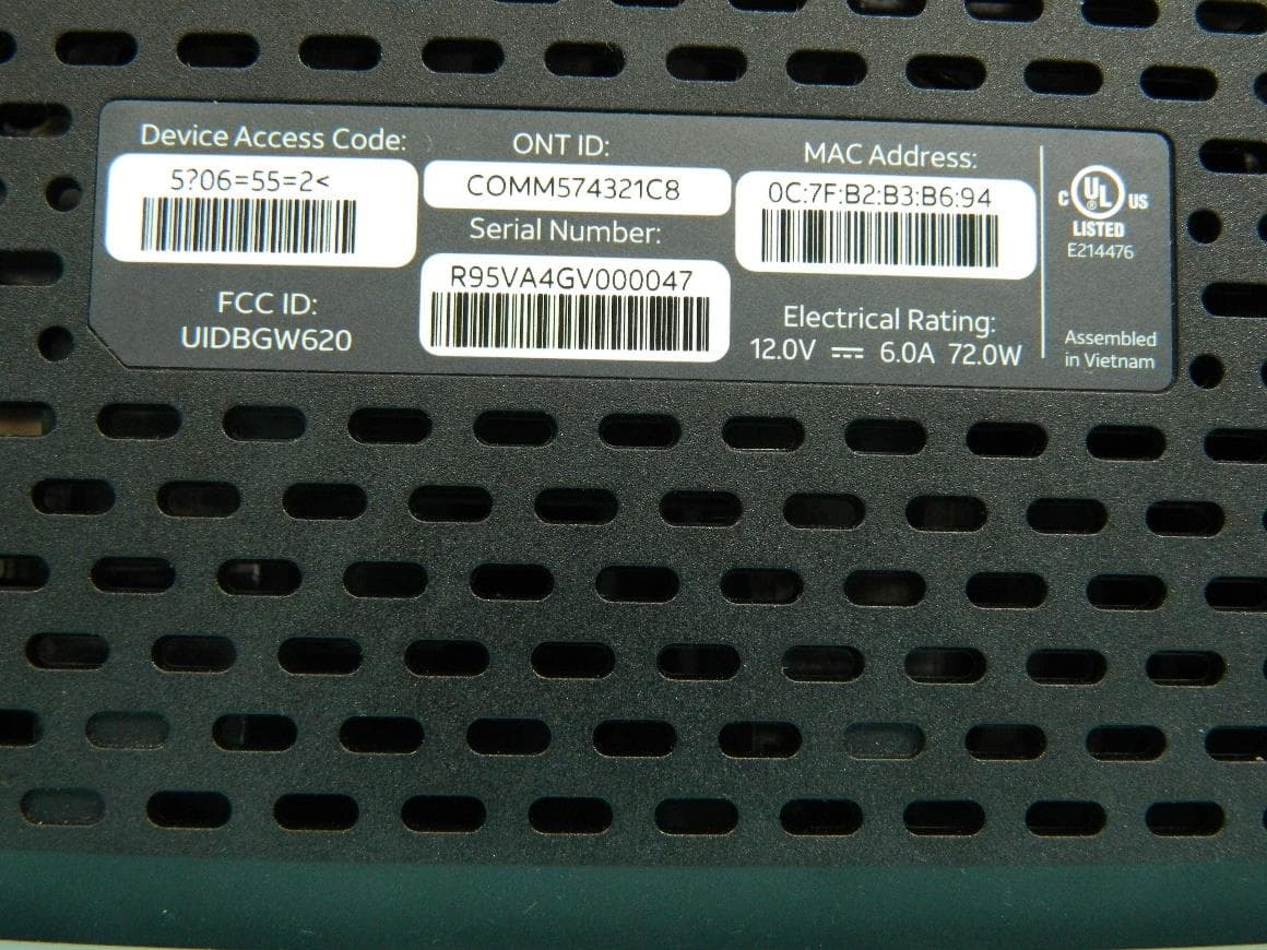
G95BGW620
Aug 26, 2024Wi-Fi 7 XGS-PON Gateway
Equipment Class
NII - Unlicensed National Information Infrastructure TX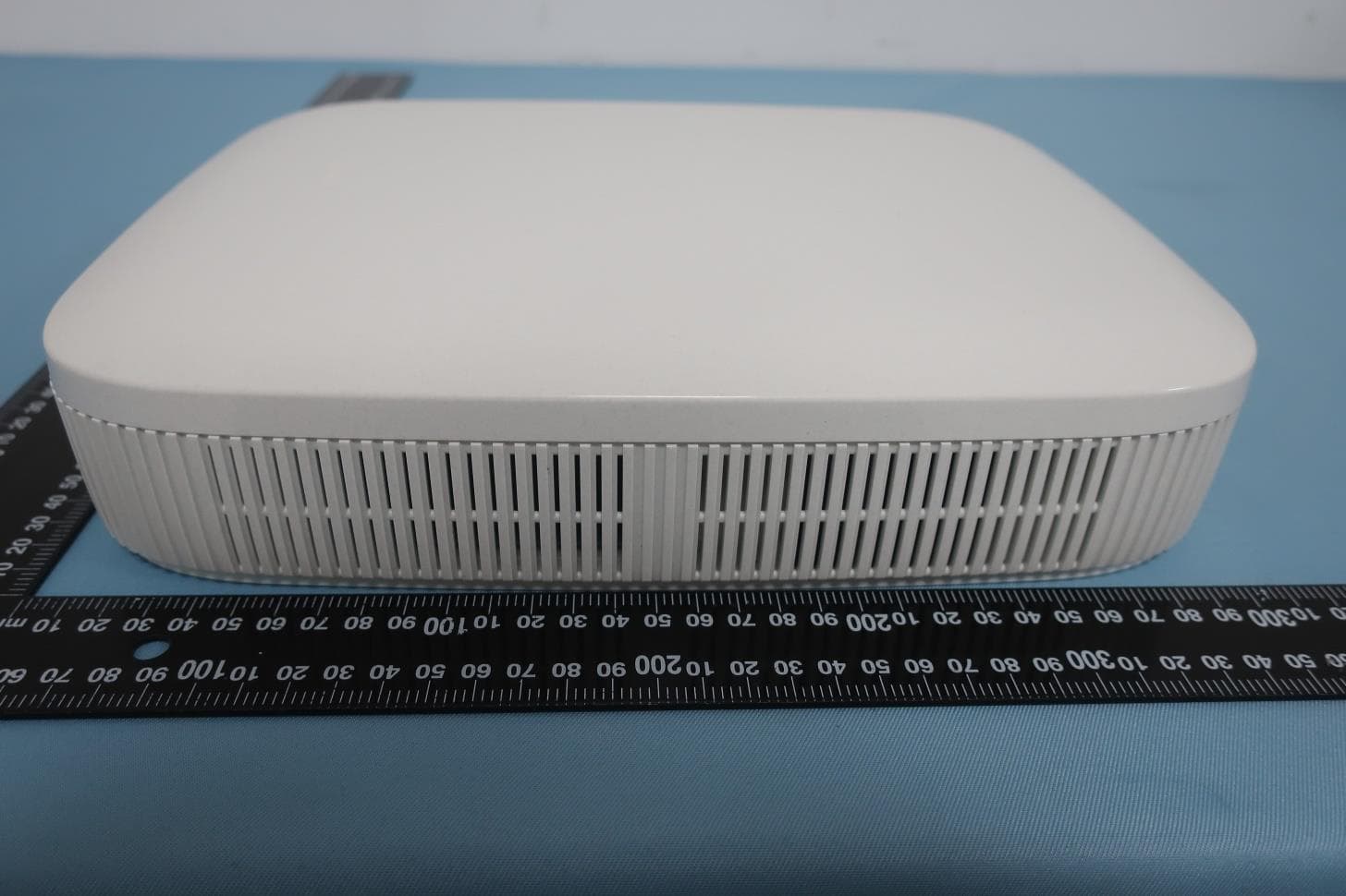
G954981X2
Jan 10, 2024DOCSIS 3.1
Equipment Class
NII - Unlicensed National Information Infrastructure TXG95OWA7111
Jul 20, 2023Wi-Fi 6E Extender
Equipment Class
6PP - 15E 6 GHz Subordinate Indoor Device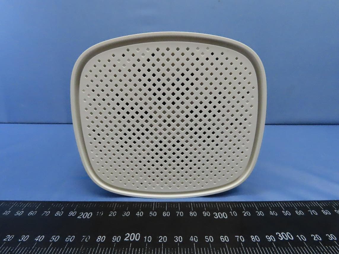
G95EWM322T
Jul 17, 2023Wireless Access Point
Equipment Class
DTS - Digital Transmission System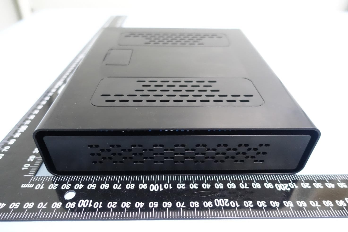
G95-CGA437T
Jan 14, 2023DOCSIS 3.1 Residential Voice Gateway
Equipment Class
NII - Unlicensed National Information Infrastructure TX