G95DCI401MCSAudio Video Apparatus
Vantiva USA LLC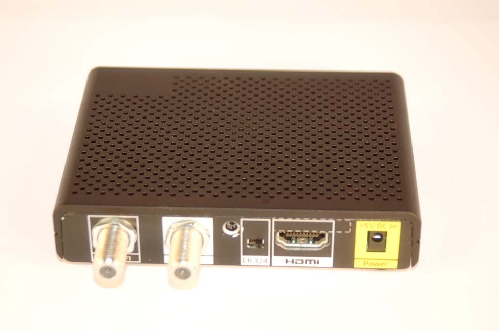
Click to zoom
Application Details
- Equipment Class
- DXX - Part 15 Low Power Communication Device Transmitter
- Date of Grant
- Nov 07, 2012
- Application Purpose
- Original Equipment
- Date of Application
- Nov 07, 2012
- Equipment Note
- Audio Video Apparatus
- Frequency Range
- 2425.00000000 - 2575.00000000
- Company
- Vantiva USA LLC
- Country
- United States
Documents & Files
Document Text
Text extracted from the exhibit documents filed with the FCC. Open a document above to read the original.
Users Manual
Red light location RF Remote Pairing Process: When multiple remotes work in a shared space, interference can result. To avoid this problem, the remote must be paired with the Digital Adapter. Step 1 Turn on your TV using the buttons on the TV or the TV remote. Make sure power is connected to your Digital Adapter and it is plugged into the TV. Note: Your TV must always be set to the proper channel (Ch 3 or Ch 4) or HDMI Input to match the output channel on the back of your Digital Adapter. Step 2 Install the batteries (included in your kit) in your new remote control. Step 3 Make certain no other Digital Adapter remote is in the area. Make sure power is connected to your Digital Adapter. Turn on your TV using the buttons on the TV or the TV remote (not a digital adapter remote in this instance). Setting Up the Remote Control Code appears on the screen. 123 Step 4 Press and hold both DTA POWER and SELECT keys at the same time. Once the red light on the remote turns on, then release both keys. Wait 10 seconds, a 3 digit validation code will display on the TV. Step 5 Enter the 3 digit code using the Digital Adapter remote. When remote is successfully paired with the Digital Adapter, the remote’s red light will blink twice. Proceed to back of this page to setup the Remote Control with your television. Setup Remote to Control the Digital Adapter Blinks twice 3698714A TIS 19/23/11 9:08 AM Step 6 Press and hold both Digit 1 and Digit 3 keys together until the red light turns on. Release both keys. Keep your eyes on the Remote so you can watch the red light. 3698714A Press and hold both buttons at the same time Keep your eyes on the remote so you can watch the red light. Setup Remote to Control the Television If you are not successful the first time, try again. Two Remotes If you were unable to program your remote, you will need to use two remotes to operate your TV: the Digital Adapter Remote and the one that came with your TV. Setting the Remote Volume 1. Use the remote control that came with your TV to adjust the volume to a comfortable level. This should be the last time you’ll use this remote for volume control. 2. Going forward use only your Digital Adapter Remote to adjust volume up or down. Caution: Don’t use your TV remote to change channels. Your TV must always be set to the proper HDMI Input, Ch 3 or Ch 4 or you will see a snowy or blank screen. Step 7 Point the new remote at the TV. Press and hold the TV POWER k e y. The remote will start searching for the right code while you are holding this key. When the TV turns off, release the key within 2 seconds to lock in the code. Step 8 Point the new remote at the TV. Press TV POWER on your Remote to turn on your TV. If your TV responds (turns on), then you have successfully programmed your Remote. The setup of the Remote is now complete. Note: Your TV must always be set to the proper channel (Ch 3 or Ch 4) or HDMI Input to match the output channel on the back of your Digital Adapter. 3698714A TIS 29/23/11 9:08 AM
Users Manual
Imp Read these instructions. ortant Safety Instructions Keep these instructions. Heed all warnings. Follow all instructions. Do not use this apparatus near water. Clean only with dry cloth. Do not block any ventilation openings. Install in accordance with the manufacturer’s instructions. Do not install near any heat sources such as radiators, heat registers, stoves, or other apparatus (including amplifiers) that produce heat. Do not defeat the safety purpose of the polarized or grounding-type plug. A polarized plug has two blades with one wider than the other. A grounding type plug has two blades and a third grounding prong. The wide blade or the third prong are provided for your safety. If the provided plug does not fit into your outlet, consult an electrician for replacement of the obsolete outlet. Protect the power cord from being walked on or pinched particularly at plugs, convenience receptacles, and the point where they exit from the apparatus. Only use attachments/accessories specified by the manufacturer. Unplug this apparatus during lightning storms or when unused for long periods of time. Refer all servicing to qualified service personnel. Servicing is required when the apparatus has been damaged in any way, such as power-supply cord or plug is damaged, liquid has been spilled or objects have fallen into the apparatus, the apparatus has been exposed to rain or moisture, does not operate normally, or has been dropped. If an outside antenna or cable system is connected to the product, be sure the antenna or cable system is grounded so as to provide some protection against voltage surges and built-up static charges. To reduce the risk of fire or electric shock, do not expose this apparatus to rain or moisture. Batteries (battery pack or batteries installed) shall not be exposed to excessive heat such as sunshine, fire or the like. Warning: Use only the power supply that came with your unit. If the power supply needs to be replaced, contact your service operator or dealer to obtain an authorized replacement. Changes or modifications not expressly approved by the party responsible for compliance could void the user's authority to operate the equipment. NO This equipment has been tested and found to comply with the limits for a Class B digital device, pursuant to part 15 of the FCC Rules. These limits are designed to provide reasonable protection against harmful interference in a residential installation. TE This equipment generates, uses and can radiate radio frequency energy and, if not installed and used in accordance with the instructions, may cause harmful interference to radio communications. However, there is no guarantee that interference will not occur in a particular installation. If this equipment does cause harmful interference to radio or television reception, which can be determined by turning the equipment off and on, the user is encouraged to try to correct the interference by one or more of the following measures: —Reorient or relocate the receiving antenna. —Increase the separation between the equipment and receiver. —Connect the equipment into an outlet on a circuit different from that to which the receiver is connected. —Consult the dealer or an experienced radio/TV technician for help. Ens Disconnect the product from the power before you connect the product to (or disconnect it from) any other equipment. Avoid any contact with the power, which can be lethal or cause severe electric shock. uring optimum performance Do not insert anything into any opening of the case. Leave the power socket accessible so that you can unplug the set quickly. Leave 2 to 3 inches around the product to ensure proper ventilation to it. To clean the product, use a dry clean soft cloth with no cleaning solvent or abrasive products. Clean the ventilation openings regularly. Environmental information The batteries use some hazardous substances which pollute the environment. Do not dispose of them with other articles. Take care to dispose them at special collecting points. Technical specifications Model type DCI401xxxx Operating voltage 120V AC / 60 Hz / 0.5A Typical Power consumption 5.0W (typical)max 6.0W (max) Weight 0.42 Lb Dimensions (W x H x D) 4.33 x 0.96 x 3.19 Inches Operating temperature range 59 to 104° F / 15 to 40°C Storage temperature range -4 to 158°F / -20 to 70°C Manufactured under license from Dolby Laboratories. FCC Compliance Statement This device complies with part 15 of the FCC Rules. Operation is subject to the following two conditions: (1) This device may not cause harmful interference, and (2) this device must accept any interference received, including interference that may cause undesired operation. This device is intended to be attached to a receiver that is not used to receive over-the-air broadcast signals. Connection of this device in any other fashion may cause harmful interference to radio communications and is in violation of the FCC Rules, part 15. Meaning of symbols This symbol is intended to alert the user to the presence of un-insulated “dangerous voltage” within the product housing that may be of sufficient magnitude to constitute a risk of shock. This symbol is intended to alert the user to the presence of important operating and maintenance (servicing) instructions accompanying the product. !
External Photos
DCI401MCS FCC Certification Application
ID Label/Location Info
NOTES:1) Print with permanent, smudge proof, black ink to be approved by Technicolor Engineering. 2) Serial Numbers. For definition of the Numeric Instrument Serial Number see Specification # 15692080. Code 128 Barcode for Serial Number (14 digit). The Pseudo Code (first 5 Characters of the serial number) is for tracking any instrument changes after the initial productionconfiguration. 4) For Factory FGR and Pilot runs where it is determined that the build will be unsalable. Replace Regulatory Marks and UPCcodes with: FGR SAMPLE or PILOT SAMPLE NOT FOR SALE. NOT FOR SALE. When required, this will be communicated with a Factory Notice. 5) Unit Identifier - The Unit Identifier is a 10 digit decimal number that resides in the SoC of the unit. Each SoC will be programmedwith a unique number. This number is used to identify the deviceby the system head end. 3) All labels which include the UL listing marking shall comply with UL requirements. Note UL logos with less than 0.375" Dia., musthave the "R-ball" symbol (Registration Mark) removed. Create, & Releasedwg 17021420. NewPrint Spec.RKM 05/04/12 1 REVISIONS SHT.:1of 5 R.K. McNeely Technicolor THESE DRAWINGS AND SPECIFICATIONS ARE THE PROPERTY OF TECHNICOLOR AND SHALL NOT BE REPRODUCED, OR COPIED OR USED AS THE BASIS FOR THE MANUFACTURE OR SALE OF APPARATUS OR DEVICES WITHOUT PERMISSION. LABEL SPECIFICATION, DCI401MCS S Safety Critical This Label may require review byProduct Certification and Compliance.See Specification, "Component SafetyRequirements" 15092970 paragraph 5. 17021420 Unit Identifier: 12345 67890 The man readable Unit Identifier will have 5 digits, a blank space, and 5 digits.The barcode will contain the blank space. not < 0.375” >= 0.375” Add Carton ID barcodeto master pack. Roll to1700935ARKM 07/12/12 2 6) Carton ID Logic: AMMPYWWDCXXXX A = OEM Designator. A = Technicolor. (Always “A”) MM = Model Number 01-99 01 = DCI401MCS P = Location where palletized 6 = Foxconn (Shanghai Songjiang) A = Indianapolis Y = Reserved for warehouse re-palletization Y = Year (0 = 2010 , 1 = 2011, etc.) D = Day carton completed (Sunday = 1, Monday = 2, etc.)C = Identifies the barcode as a Carton ID. (Always “C”) XXXX = counter 0001 - 9999 resets back to 0001 each day. WW = Week (01-52) Specification Number: 17009260 REVISIONS SHT.:2of5 R.K. McNeely Technicolor THESE DRAWINGS AND SPECIFICATIONS ARE THE PROPERTY OF TECHNICOLOR AND SHALL NOT BE REPRODUCED, OR COPIED OR USED AS THE BASIS FOR THE MANUFACTURE OR SALE OF APPARATUS OR DEVICES WITHOUT PERMISSION. LABEL SPECIFICATION, DCI401MCS IRD S Safety Critical This Label may require review byProduct Certification and Compliance.See Specification, "Component SafetyRequirements" 15092970 paragraph 5. 17021420 Model: DCI401MCS S/N: PMMMMYWWDPLXXX Unit Identifier: 12345 67890 Rating +5VDC 1.5A Manufactured under license fromDolby Laboratories.Made in China for Technicolor. Audio Video Apparatus6LA7 E229301 FCC ID: G95DCI401MCS Note: All graphics Arial Narrow Bold 6pt. Numeric Serial NumberCode 128Unit IdentifierInterleave dI2of5 Pseudo Code Plant 161 DCI401MCS De scription CONFIG A 60001 Initial Startup Configuration CONFIG B Instrument label Model: DCI401MCS S/N: PMMMMYWWDPLXXX Unit Identifier: 12345 67890 Rating +5VDC 1.5AManufactured under license fromDolby Laboratories.Made in China for Technicolor. Audio Video Apparatus6LA7 E229301 FCC ID: G95DCI401XXXX Specification Number: 17008050 REVISIONS SHT.:3of5 R.K. McNeely Technicolor THESE DRAWINGS AND SPECIFICATIONS ARE THE PROPERTY OF TECHNICOLOR AND SHALL NOT BE REPRODUCED, OR COPIED OR USED AS THE BASIS FOR THE MANUFACTURE OR SALE OF APPARATUS OR DEVICES WITHOUT PERMISSION. LABEL SPECIFICATION, DCI401MCS Carton S Safety Critical This Label may require review byProduct Certification and Compliance.See Specification, "Component SafetyRequirements" 15092970 paragraph 5. 17021420 Gift carton label Model: DCI401MCS Technicolor USA, Inc.101 West 103rd StreetIndianapolis, IN 46290-1024 S/N: PMMMMYWWDPLXXXUnit Identifier: 12345 67890 Part: 17010680 Numeric Serial NumberCode 128Unit IdentifierInterleave dI2of5 Place on gift cartonwithin target area. Specification Number: 1700935A REVISIONS SHT.:4of5 R.K. McNeely Technicolor THESE DRAWINGS AND SPECIFICATIONS ARE THE PROPERTY OF TECHNICOLOR AND SHALL NOT BE REPRODUCED, OR COPIED OR USED AS THE BASIS FOR THE MANUFACTURE OR SALE OF APPARATUS OR DEVICES WITHOUT PERMISSION. LABEL SPECIFICATION, DCI401MCS Carton S Safety Critical This Label may require review byProduct Certification and Compliance.See Specification, "Component SafetyRequirements" 15092970 paragraph 5. 17021420 Multi-pack carton label Technicolor USA, Inc. 101 West 103rd Street Indianapolis, IN 46290-1024 Model: DCI401MCSContains ten (10) DCI401MCS S/N: PMMMMYWWDPLXXX S/N: PMMMMYWWDPLXXXS/N: PMMMMYWWDPLXXXS/N: PMMMMYWWDPLXXXS/N: PMMMMYWWDPLXXX S/N: PMMMMYWWDPLXXX S/N: PMMMMYWWDPLXXXS/N: PMMMMYWWDPLXXX S/N: PMMMMYWWDPLXXX S/N: PMMMMYWWDPLXXX Numeric Serial NumberCode 128 Technicolor USA, Inc.101 West 103rd Street Indianapolis, IN 46290-1024 M o d e l : D C I 4 0 1 M C S C o n t a i n s t e n ( 1 0 ) D C I 4 0 1 M C S S / N : P M M M M Y W W D P L X X X S / N : P M M M M Y W W D P L X X X S / N : P M M M M Y W W D P L X X X S / N : P M M M M Y W W D P L X X X S / N : P M M M M Y W W D P L X X X S / N : P M M M M Y W W D P L X X X S / N : P M M M M Y W W D P L X X X S / N : P M M M M Y W W D P L X X X S / N : P M M M M Y W W D P L X X X S / N : P M M M M Y W W D P L X X X Place on Master Pack Cartonwithin target area. Carton ID: AMMPYWWDCXXXX Carton ID Code 128See Note 6. Specification Number: 17022270 REVISIONS SHT.:5of5 R.K. McNeely Technicolor THESE DRAWINGS AND SPECIFICATIONS ARE THE PROPERTY OF TECHNICOLOR AND SHALL NOT BE REPRODUCED, OR COPIED OR USED AS THE BASIS FOR THE MANUFACTURE OR SALE OF APPARATUS OR DEVICES WITHOUT PERMISSION. LABEL SPECIFICATION, DCI401MCS PCB S Safety Critical This Label may require review byProduct Certification and Compl…
Text truncated - open the document above for the full version.
ID Label/Location Info
Part Number: 17027280 1 REVISIONS SHT.:1of1 R.K. McNeely Technicolor THESE DRAWINGS AND SPECIFICATIONS ARE THE PROPERTY OF TECHNICOLOR AND SHALL NOT BE REPRODUCED, OR COPIED OR USED AS THE BASIS FOR THE MANUFACTURE OR SALE OF APPARATUS OR DEVICES WITHOUT PERMISSION. PREPRINTED LABEL SPECIFICATION, DCI401MCS IRD S Safety Critical This Label may require review byProduct Certification and Compliance.See Specification, "Component SafetyRequirements" 15092970 paragraph 5. Label Feed Direction 17027280 Dimensions: Inches 1) Labels must be suitable for use in a Thermal Printer. Reference Material Fasson 12906. (Contact User Plants for printer models)2) Blank face stock and adhesive to meet the following requirements. A.) Peel Test: 1lb/in Applied @ 180 degree angle. B.) This label must pass environmental durability test spec 1533282% for permanent labels.C.) This label must comply with the test for permanence described in “Marking and Instructions” UI6500. 3) Preprinted graphics to be black printing.4) Labels to be supplied on rolls with 3 inch I.D. Core and not to exceed 8 inch O.D.5) Die cut labels to have trim removed.6) Samples to be supplied to Technicolor R&D Department for Approval.7) All parts on this document/drawing must comply with the requirements and procedures specified in the Technicolor green (RoHS) supplier handbook 36033050. Create & Release17027280.R.K.M 06/07/12 1.2” 1.2” Rating +5VDC 1.5A Manufactured under license fromDolby Laboratories.Made in China for Technicolor. Audio Video Apparatus6LA7 E229301 FCC ID: G95DCI401MCS Perf in liner between labels. Note: Arial Narrow 6pt font .
Internal Photos
Cable Tuner 3 / 4 Modulator RF4CE Antennae Green Peak RF4CE Xcvr
Test Report
Engineering Test Report No. 1202569-01 Measurement of RF Emissions from a DCI401MCS Data Terminal Adaptor For Technicolor USA Inc. 101 W 103rd St Indianapolis, IN 46290 P.O. Number 1010129956 Date Tested July 30 through August 1, 2012 Test Personnel Richard E. King Test Specification FCC "Code of Federal Regulations” Title 47 Part15, Subpart C Industry Canada RSS-GEN Industry Canada RSS-210 Test Report By: Richard E. King EMC Engineer Requested By: Rejimon Varghese Technicolor USA Inc. Approved By: Raymond J. Klouda Registered Professional Engineer of Illinois - 44894 Elite Electronic Engineering, Inc. 1516 Centre Circle Downers Grove, IL 60515 Tel : (630) 495-9770 Fax: (630) 495-9785 www.elitetest.com Engineering Test Report No. 1202569-01 TABLE OF CONTENTS PARAGRAPH DESCRIPTION OF CONTENTS PAGE NO. THIS REPORT SHALL NOT BE REPRODUCED, EXCEPT IN FULL, WITHOUT THE WRITTEN APPROVAL OF ELITE ELECTRONIC ENGINEERING INCORPORATED. Page 2 of 52 1. Introduction ................................................................................................................................................... 4 1.1. Scope of Tests ..................................................................................................................................... 4 1.2. Purpose ............................................................................................................................................... 4 1.3. Deviations, Additions and Exclusions .................................................................................................. 4 1.4. EMC Laboratory Identification ............................................................................................................. 4 1.5. Laboratory Conditions.......................................................................................................................... 4 2. Applicable Documents .................................................................................................................................. 4 3. EUT Setup and Operation ............................................................................................................................ 4 3.1. General Description ............................................................................................................................. 4 3.1.1. Power Input ................................................................................................................................. 5 3.1.2. Peripheral Equipment ................................................................................................................. 5 3.1.3. Signal Input/Output Leads .......................................................................................................... 5 3.1.4. Grounding ................................................................................................................................... 5 3.2. Operational Mode ................................................................................................................................ 5 3.3. EUT Modifications ................................................................................................................................ 5 4. Test Facility and Test Instrumentation ......................................................................................................... 5 4.1. Shielded Enclosure .............................................................................................................................. 5 4.2. Test Instrumentation ............................................................................................................................ 5 4.3. Calibration Traceability ........................................................................................................................ 5 4.4. Measurement Uncertainty ................................................................................................................... 5 5. Test Procedures ........................................................................................................................................... 6 5.1. Powerline Conducted Emissions ......................................................................................................... 6 5.1.1. Requirements .............................................................................................................................. 6 5.1.2. Procedures .................................................................................................................................. 6 5.1.3. Results ........................................................................................................................................ 7 5.2. Duty Cycle Factor Measurements ....................................................................................................... 7 5.2.1. Procedures .................................................................................................................................. 7 5.2.2. Results ........................................................................................................................................ 7 5.3. Radiated Measurements ..................................................................................................................... 7 5.3.1. Requirements .............................................................................................................................. 7 5.3.2. Procedures .................................................................................................................................. 7 5.3.3. Results ........................................................................................................................................ 8 5.4. Bandedge Compliance ........................................................................................................................ 8 5.4.1. Requirement......................................…
Text truncated - open the document above for the full version.
Test Setup Photos
Engineering Test Report No. 1202569-01 Page 13 of 52 Figure 2 Test Setup for Radiated Emissions, 30MHz to 1GHz – Horizontal Polarization Test Setup for Radiated Emissions, 30MHz to 1GHz – Vertical Polarization Engineering Test Report No. 1202569-01 Page 14 of 52 Figure 4 Test Setup for Radiated Emissions, above 1GHz – Horizontal Polarization Test Setup for Radiated Emissions, above 1GHz – Vertical Polarization
Contact Information
Applicant
Robert Lyall(Principal Certification Engineer)
Test Firm
Elite Electronic Engineering Inc.Kevin Halpin
Technical Specifications
| # | Rule Parts | Frequency Range | Power Output |
|---|---|---|---|
| 1 | 15C | 2.42 GHz - 2.58 GHz | - |
Other Applications from Vantiva USA LLC
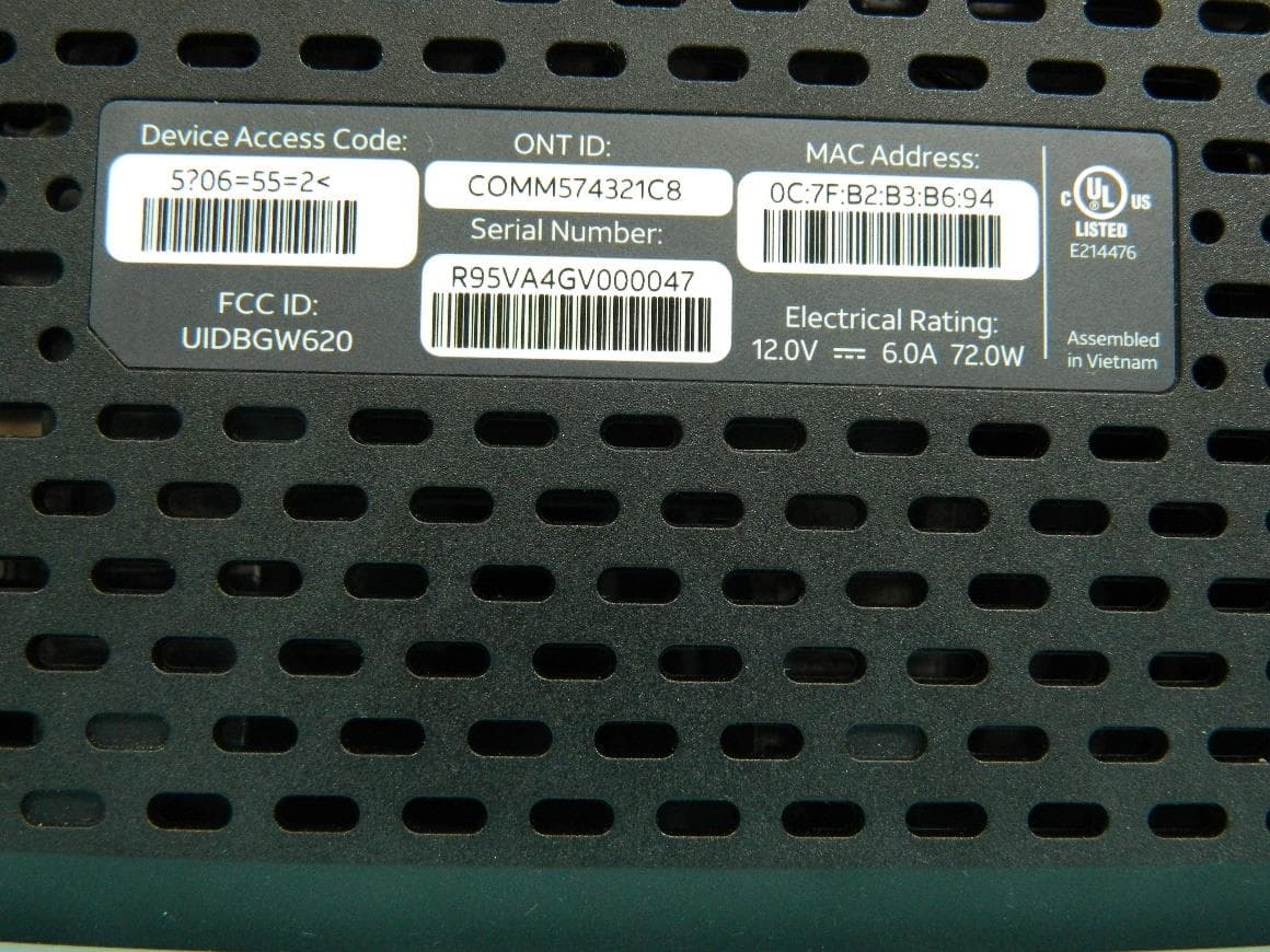
G95BGW620
Aug 26, 2024Wi-Fi 7 XGS-PON Gateway
Equipment Class
NII - Unlicensed National Information Infrastructure TX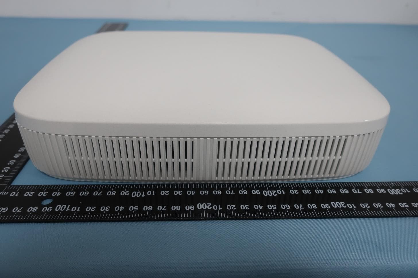
G954981X2
Jan 10, 2024DOCSIS 3.1
Equipment Class
NII - Unlicensed National Information Infrastructure TXG95OWA7111
Jul 20, 2023Wi-Fi 6E Extender
Equipment Class
6PP - 15E 6 GHz Subordinate Indoor Device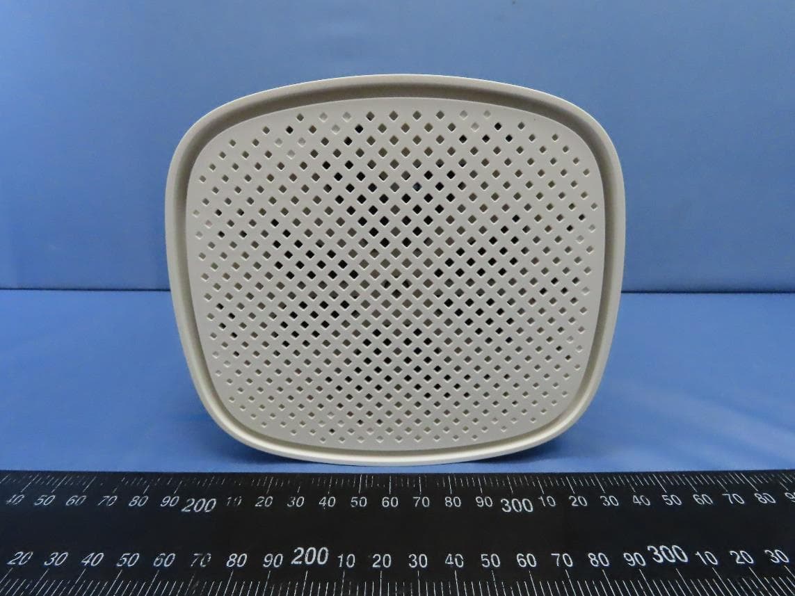
G95EWM322T
Jul 17, 2023Wireless Access Point
Equipment Class
DTS - Digital Transmission System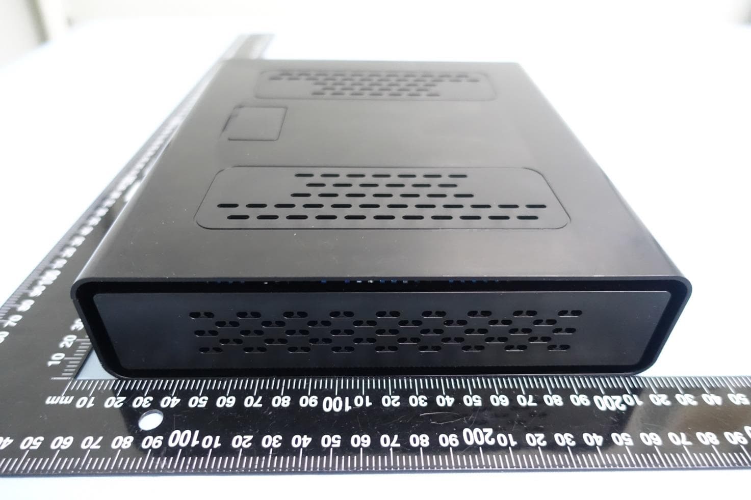
G95-CGA437T
Jan 14, 2023DOCSIS 3.1 Residential Voice Gateway
Equipment Class
NII - Unlicensed National Information Infrastructure TX