G95REM002RF Remote Control for Satellite Receiver
Vantiva USA LLC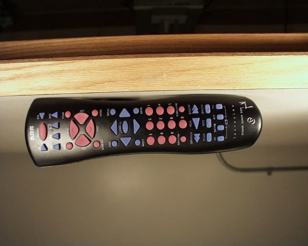
Click to zoom
Application Details
- Equipment Class
- DXX - Part 15 Low Power Communication Device Transmitter
- Date of Grant
- Nov 22, 1998
- Application Purpose
- Original Equipment
- Date of Application
- Oct 26, 1998
- Equipment Note
- RF Remote Control for Satellite Receiver
- Frequency Range
- 308.50000000 - 308.50000000
- Company
- Vantiva USA LLC
- Country
- United States
Documents & Files
Document Text
Text extracted from the exhibit documents filed with the FCC. Open a document above to read the original.
Users Manual
COMMUNICATION CERTIFICATION LABORATORYTEST REPORT: 73-6665 FCC ID: G95REM002 Exhibit 8 Page 30 of 36 Exhibit 8: User’s Manual The user’s manual was sent as two pdf files. One file contains the first half and the second file contains the second half of the user’s manual. The compliance statement for the CRK 76 is enclosed on page 2 of the manual.
Users Manual
The Menu System 39 ã Setup and Connections What ’s a Menu? The on-screen menu is a list of choices, just like a menu in a restaurant. And, just as a restaurant menu is divided into sections such as appetizers, entrees, and desserts, the on- screen menus are also separated into sections to help you find the information you need. Don’t Forget Point and Select As with all of the on-screen displays, you use Point and Select to navigate. 1 ãã Troubleshooting 5 Using the Remote ã 2 The Menu System The Menu System 4 Program Guides 3 The Menu System 40 Using the Menu System To bring up the Main menu, press MENU on the remote. Use point and select to choose an item from the Main menu. To use the menu system, you need to know the Point and Select rule. Use the arrows on the remote to point to an item on the screen, and then press OK to select it. Back and Help There are Back and Help buttons at the top of most screens. Point to Back and press OK to leave that screen. Point to Help to see more information about that screen. Exiting a Screen There are three ways to exit a menu: •Point to Back and press OK. •Press the CLEAR button on the remote control. The on-screen displays clear from the screen and you return to TV viewing. •Press the GO BACK button on the remote. You return to the previous on-screen display or normal programming. Using Help All menus have a Help button. For example, selecting the Help button from the Main menu shows you information about using the Main menu screen. The rest of the Help buttons in the menu system bring up helpful information explaining one aspect of that menu. Use the MENU button to bring up the Main menu, and then use Point and Select to choose a menu option. Context-Sensitive Help Most of the screens contain information to help you decide what to do next. If you get stuck, look for the help text. If the Main menu doesn’t appear when you press MENU, the remote might not be in DSS ® mode. Try pressing the DSS button on the remote, and then OK. The Menu System 41 Menu Descriptions This section briefly describes each of the available Main menu options. More information about each menu and its features is included later in this chapter. Program Guide Shows the on-screen programming schedules. Mailbox Use to read mail messages from your program providers. Purchases Use to review or cancel upcoming purchases, and to review past purchases. Timers Allows you to schedule the digital satellite system to tune to a specific channel at a specific time. Profiles Allows you to set ratings limits, spending limits, and viewing hours, as well as create favorite channel lists. Options Allows you to find out more about the receiver and remote, change how your system looks, run the system test and install a new access card. Dish Pointing Use to find your dish pointing coordinates, and to access the on-screen signal strength meter. Home Control With the proper equipment, this feature lets you control certain devices and appliances in your house. Don’t Be Afraid to Explore Once you’ve learned the basics, feel free to poke around the menu system because exploring is the best way to learn. The context-sensitive help at the bottom of the screen provides instructions for getting through any particular menu or control panel. Remember, press CLEAR at any time to leave the menu system and return to regular system viewing. Don’t Forget About the CLEAR Button Press the CLEAR button on the remote to remove the on-screen menus and return to normal viewing. The Menu System 42 The Program Guide Selecting Program Guide brings up your default program guide: the Detail Guide, the Grid Guide or SurfGuide. Anatomy of a Program Guide The following diagram shows you the kind of information you will see in the Detail Guide and Grid Guide. Bringing Up the Program Guides Besides selecting Program Guide in the Main menu, you can press the GUIDE button on the remote. Displays more sorting options “Family” is one of five selectable Profiles Program titles and information Returns you to previous screen Help gives you more information Sort the guide by: Topics, Movies, or Sports Sorts the current guide alphabetically by title Searches guide for specific information Takes you to the Main menu Scrolls through the guide Shows all available programs Indicates current time Want More Information? Read the section in this book called Program Guides for all the details. The Menu System 43 The Mailbox The mailbox shows you messages that are sent—or “mailed”—from your program providers. For example, you may receive a message calling your attention to a new service. How to Tell When you Have Mail There are two ways to tell if you have mail, depending on whether the receiver is turned on or off. •If the receiver is turned on, the mail icon in the channel banner is highlighted. •If the receiver is turned off, the power light on the front panel of the receiver flashes. Checking Your Mail Select Mailbox on the Main menu or channel banner to view your mail. 1.Point to a message and press OK. The message is opened for you to read. Mail provides the latest information from program providers. 2.Press OK again to close the letter. After you read a message and want to erase it, point to Erase Message and press OK. When you exit the display screen, messages not erased are saved in memory. The Menu System 44 Pay-Per-View Programs Pay-per-view programs (PPV) are programs that you purchase—like a movie ticket—on an event-by-event basis. For instance, there might be a specific channel that runs nothing but previews for movies. After previewing the movie, you can purchase it or find out more details about it. PPV programs can also be found in the program guide. Purchasing and Previewing There are several ways to purchase and preview PPV movies and events: •Tune to a PPV program’s channel. Program providers may offer on- screen purchase instructions, usually as the PPV program begins. •Choose a PPV program from the program guide. •Preview a…
Text truncated - open the document above for the full version.
Users Manual
SATELLITE RECEIVER USER'S GUIDE Safety Information WARNING TO REDUCE THE RISK OF ELECTRIC SHOCK, DO NOT REMOVE COVER (OR BACK). NO USER SERVICEABLE PARTS INSIDE. REFER SERVICING TO QUALIFIED SERVICE PERSONNEL. This symbol indicates “dangerous voltage” inside the product that presents a risk of electric shock or personal injury. This symbol indicates important instructions accompanying the product. RISK OF ELECTRIC SHOCK DO NOT OPEN WARNING To reduce risk of fire or shock hazard, do not expose this receiver to rain or moisture. Cautions Do not stack electronic components or other objects on top of the Receiver. The slots on top of the receiver must be left uncovered to allow proper airflow to the unit. Blocking the airflow to the unit could impair performance or damage your receiver and other components. Do not stack the receiver on top of a “hot component” such as an audio power amplifier. FCC Regulations state that unauthorized changes or modifications to this equipment may void the user’s authority to operate it. The RF remote control complies with part 15 of the FCC Rules. Operation is subject to the following two conditions: 1) The RF remote control may not cause harmful interference and; 2) The RF remote control must accept any interference received, including interference that may cause undesired operation. Note to Cable TV Installer:This reminder is provided to call your attention to Article 820-40 of the National Electrical Code (Section 54 of the Canadian Electrical Code, Part 1) which provides guidelines for proper grounding and, in particular, specifies that the cable ground shall be connected to the grounding system of the building as close to the point of cable entry as practical. Note to Satellite Dish Installer:This reminder is provided to call your attention to Article 810 and in particular article 810-15 of the National Electrical Code which covers proper installation and grounding of television receiving equipment as well as to article 820-40 of the National Electrical Code which specifies that the satellite dish cable ground shall be connected to the grounding system of the building as close to the point of cable entry as practical. IMPORTANT NOTICE:This device incorporates an anticopy process technology that is protected by U.S. patents and other intellectual property rights. The anticopy process is licensed for non-commercial, home use only. Reverse engineering or disassembly is prohibited. Care and Cleaning:Use a soft cloth or dusting attachment of your vacuum cleaner to dust your receiver. Remove dust from the ventilation holes on the top and bottom. Plastic surfaces are easily scratched and can be marred by alcohol and various solvents. Avoid excessive use of oil-based furniture polishes since the materials used in the cabinet will accumulate more dust. A non-abrasive, anti-static cleaner/polisher is recommended. Table of Contents 1 Setup and Connections ........................................ 3 Step 1: Unpack the DSS® System ................................................... 4 Step 2: Connect Your Receiver to Your TV and Other Devices ..... 4 Things to Know Before Connecting Components .................. 4 Jacks and Cables ........................................................................ 5 Back of the Receiver ................................................................. 6 Basic Connection ....................................................................... 7 Advanced Connection .............................................................. 8 Step 3: Connect the VCR Controller ............................................... 9 Locating the VCR’s Infrared Remote Control Sensor .............. 9 Selecting a VCR Type ................................................................ 9 Step 4: Find the Video Input Channel on Your TV ...................... 11 Step 5: Interactive Setup ............................................................... 12 Step 6: Place Batteries in the Remote Control ............................ 12 STEP 7: Plug in and Turn on the System ....................................... 12 Step 8: Order DSS ® Programming ................................................. 13 Using the Remote ............................................... 15 Remote Control Buttons ............................................................... 16 The Point and Select Method ....................................................... 18 Programming the Remote Control .............................................. 19 TV Codes .................................................................................. 21 VCR Codes ............................................................................... 22 Cable Box Codes ...................................................................... 23 Program Guides .................................................. 25 Bringing Up the Program Guides ........................................... 26 Anatomy of a Program Guide ...................................................... 26 The Channel Banner ...................................................................... 27 Using the GUIDE Button ......................................................... 28 Getting Around in the Guides ............................................... 28 Tuning to a Program ............................................................... 29 Additional Program Guides .................................................... 30 Sorting the Guides ................................................................. 32 The Menu System ............................................... 39 Using the Menu System ................................................................ 40 Back and Help ......................................................................... 40 Menu Descriptions .................................................................. 41 The Program Guide ....................................................................... 42 The Mailbox .........…
Text truncated - open the document above for the full version.
Block Diagram
COMMUNICATION CERTIFICATION LABORATORYTEST REPORT: 73-6665 FCC ID: G95REM002 Exhibit 4 Page 6 of 36 Exhibit 4: Block Diagrams BATTERY +V - V KEYPAD MICRO - PROCESSOR 8 MHZ CERAMIC +V IR XMITTER RF XMITTER 308.5 MHZ SAW +V CONTROL DATA
Cover Letter(s)
COMMUNICATION CERTIFICATION LABORATORYTEST REPORT: 73-6665 FCC ID: G95REM002 Exhibit 13 Page 36 of 36 Exhibit 13: Cover Letters October 26, 1998 FEDERAL COMMUNICATIONS COMMISSION Equipment Authorization Division 7435 Oakland Mills Road Columbia, MD 21046 To Whom It May Concern: Enclosed is a FCC Part 15, Subpart C, Section 15.231 Certification application for the Thomson Consumer Electronics, Inc. Model CRK 76, FCC ID: G95REM002. Please let me know if I can be of further assistance. Sincerely yours, COMMUNICATION CERTIFICATION LABORATORY Joseph W. Jackson V.P. Marketing
External Photos
COMMUNICATION CERTIFICATION LABORATORYTEST REPORT: 73-6665 FCC ID: G95REM002 Exhibit 3 Page 4 of 36 Exhibit 3: Photographs of Overall Appearance Front View of the CRK 76 COMMUNICATION CERTIFICATION LABORATORYTEST REPORT: 73-6665 FCC ID: G95REM002 Exhibit 3 Page 5 of 36 Back View of the CRK 76
ID Label/Location Info
COMMUNICATION CERTIFICATION LABORATORYTEST REPORT: 73-6665 FCC ID: G95REM002 Exhibit 1 Page 1 of 36 Exhibit 1: FCC ID Label Equipment Identification Label In accordance with the requirements of Sections 15.19 (a), 2.925 and 2.926 of the FCC Rules, the following information will be permanently affixed to the Thomson Consumer Electronics, Inc. Model CRK 76 as shown in the photograph below. Due to the size of the equipment, the label contains only the FCC ID only, and the compliance statement is provided in the User’s manual. The compliance statement for the CRK 76 is enclosed on page 2 of the manual. Photograph of the back exterior view showing the label placement. COMMUNICATION CERTIFICATION LABORATORYTEST REPORT: 73-6665 FCC ID: G95REM002 Exhibit 1 Page 2 of 36 Photograph of the back exterior view.
Internal Photos
COMMUNICATION CERTIFICATION LABORATORYTEST REPORT: 73-6665 FCC ID: G95REM002 Exhibit 9 Page 31 of 36 Exhibit 9: Internal Photographs Component Side of the CRK 76 COMMUNICATION CERTIFICATION LABORATORYTEST REPORT: 73-6665 FCC ID: G95REM002 Exhibit 9 Page 32 of 36 Solder Side of the CRK 76
Internal Photos
COMMUNICATION CERTIFICATION LABORATORYTEST REPORT: 73-6665 FCC ID: G95REM002 Exhibit 9 Page 31 of 36 Exhibit 9: Internal Photographs Solder Side of the CRK 76 COMMUNICATION CERTIFICATION LABORATORYTEST REPORT: 73-6665 FCC ID: G95REM002 Exhibit 9 Page 32 of 36 Component Side of the CRK 76
Schematics
COMMUNICATION CERTIFICATION LABORATORYTEST REPORT: 73-6665 FCC ID: G95REM002 Exhibit 5 Page 7 of 36 Exhibit 5: Schematic Diagrams
Schematics
VDD B B 077-060 CR2 JC2 JW2 JW1 01-02-98 MAR 18,1998 SSDXX15252_96ES01PIL_0_SLH_R01 CRK7686 1 02 15252940 3-24-1998_12:48 C104 2% 20 R102 2% 3300 22K R103 2% 120 R104 050-510 Q5 CR3 046-300 043-240 CR1 16V 10UF C2 ANT PAUSE DIG5 CNTL DIG0 FF DIG3 DIG4 DIG9 DIG1 CH+ DIG7 LFT REV AUX GB RGT SKIP VOL+ DIG2 DIG8 SWAP VOL- DN PWR PIP REC STOP PLAY Q102 946-660 UPOK A A B B A A A A B A Q101 070-660 8 C103 CR202 115-810 CR203 115-810 CR204 115-810 115-810 CR205 CR206 115-810 TV VCRSAT MUTE GUIDE MENU CLEARLITE R60 330 331-140 Y1 WHO HOME DVD RESET INFOSOUND 25V C1 100NF R20 R21 R22 R23 DIG6 CH- U1 * POS NEG 22K R101 R201 1K 050-510 Q201 B 10 R202 XX15179-29A Y101 C105 470 A JC3 258-470 L101 FIRST MADE FOR: USED ON: DOC_ID:DIST. CODE 109 SHEET NO. 12 345678 876543 21 A B C D E F G HH G F E D C B A TCE SUB NO. BOM EFF: M. INDICATES A HIERARCHICAL SIGNAL FLOW DIRECTION NOT NECESSARILY CURRENT FLOW. A. INDICATES SEE BOM FOR CHASSIS VARIATIONS. J. INDICATES A SURFACE MOUNTED (0805 TYPE) DEVICE I. INDICATES A SURFACE MOUNTED (1206 TYPE) DEVICE H. INDICATES CONNECTION POINT VIA HEADER OR HARD WIRE. C. FOR TOLERANCE INFORMATION LOOK ON THE DRAWING BILL OF MATERIAL C. INDICATES COLD GROUND. B. INDICATES SERVICES TEST POINT. AXXXX TPXXXX B. VALUES BELOW 1.0 ARE IN uf, UNLESS OTHERWISE SPECIFIED. A. INDICATES ATE TEST POINT. 3. SYMBOLS 2. CAPACITORS LIST. UNLESS OTHERWISE SPECIFIED. D. INDICATES HOT GROUND. E. INDICATES CONNECTION POINT VIA INSULATION DISPLACEMENT TYPE PLUGGABLE CABLE ASSEMBLY. F. INDICATES CONNECTION POINT VIA HIGH CURRENT TYPE PLUGGABLE CABLE ASSEMBLY. G. INDICATES CONNECTION POINT VIA WIRE-WRAP STAKE. K. INDICATES A PART THAT IS CLASSIFIED AS SAFETY CRITICAL, (S) OR SAFETY RELATED, (R) ON THE DRAWING LIST. ITEMS CLASSIFIED "S" HAVE SPECIAL SAFETY CHARACTERISTICS WHILE THOSE ITEMS CLASSIFIED "R" ARE RESTRICTED BECAUSE OF THE ARE PERMITTED EXCEPT BY SPECIAL DIRECTIVE OF RCA DESIGN ENGINEERING. L. "3" INDICATES CLOCKWISE END. 3 2 1 M. INDICATES SIGNAL FLOW DIRECTION NOT NECESSARILY CURRENT FLOW. 4. CHASSIS VARIATIONS B. SURFACE MOUNTED (0805 SIZE) ARE 1/10W, 5% TOLERANCE. A. SURFACE MOUNTED (1206 SIZE) ARE 1/8W, 5% TOLERANCE. 1. RESISTORS D. VALUES ARE IN OHMS, K=X1000, M=X1,000,000. GENERAL NOTES: A. VALUES 1.0 AND ABOVE ARE IN pf, UNLESS OTHERWISE SPECIFIED. H NOTE, UNLESS OTHERWISE SPECIFIED: I. INDICATES A HIERARCHICAL COLD GROUND. H APPLICATION. NO SUBSTITUTIONS FOR THESE PARTS C. AXIAL LEADED ARE 1/4W, 5% TOLERANCE. N. INDICATES A SAFETY NODE ~W~ 9 OSCIN 10 OSCOUT P00 19 P01 20 P0221 P03 23 P04 4 P05 5 6 P06 26 P22 P23 27 28 P24 1 P25 P26 2 3 P27 11 P31 P32 12 13 P33 P34 14 P36 17 18 PREF1 22 VSS24 P21 25 P20 8 VDD 7 P07 16 P37 15 P35 15 25 7 24 13 16 11 12 22 18 14 17 109 3 27 2 26 1 28 6 5 4 23 21 20 19 8 12 1 21 3 +3V CRK7686 REMOTE TRANSMITTER KEY MATRIX SAME AS CRK76TA1,REV 2 8MZ 307.3MHZ * * * *
Test Report
COMMUNICATION CERTIFICATION LABORATORYTEST REPORT: 73-6665 FCC ID: G95REM002 Exhibit 6 Page 8 of 36 Exhibit 6: Test Report TEST REPORT FROM: COMMUNICATION CERTIFICATION LABORATORY 1940 W. Alexander Street Salt Lake City, Utah 84119-2039 Type of Report: Certification TEST OF: CRK 76 FCC ID: G95REM002 To FCC PART 15, Subpart C Section 15.231 Test Report Serial No: 73-6665 Applicant: Thomson Consumer Electronics, Inc. 10330 North Meridian Street Indianapolis, IN 46290 Date(s) of Test: October 19 – 20, 1998 Issue Date: October 26, 1998 Equipment Receipt Date: October 19, 1998 COMMUNICATION CERTIFICATION LABORATORYTEST REPORT: 73-6665 FCC ID: G95REM002 Exhibit 6 Page 9 of 36 CERTIFICATION OF ENGINEERING REPORT This report has been prepared by Communication Certification Laboratory to determine compliance of the device described below with the notification requirements of FCC Part 15, Subpart C Section 15.231. This report may be reproduced in full, partial reproduction may only be made with the written consent of the laboratory. The results in this report apply only to the sample tested. -Applicant:Thomson Consumer Electronics, Inc. - Manufacturer:Thomson Consumer Electronics, Inc. -Brand Name:RCA -Model Number:CRK 76 -FCC ID:G95REM002 On this 26 th day of October 1998, I, individually, and for Communication Certification Laboratory, certify that the statements made in this engineering report are true, complete, and correct to the best of my knowledge, and are made in good faith. Although NVLAP has recognized that the Communication Certification Laboratory EMC testing facilities are in good standing, NVLAP does not endorse the product described in this report. COMMUNICATION CERTIFICATION LABORATORY Checked by: Roger J. Midgley EMC Engineering Manager Tested by: Jeffrey L. Draney EMC Technician COMMUNICATION CERTIFICATION LABORATORYTEST REPORT: 73-6665 FCC ID: G95REM002 Exhibit 6 Page 10 of 36 SECTION 1.0 CLIENT INFORMATION 1.1 Client Information: Company Name: Thomson Consumer Electronics, Inc. 10330 North Meridian Street Indianapolis, IN 46290 Contact Name:Eugene E. Janson Title:Compliance Manager COMMUNICATION CERTIFICATION LABORATORYTEST REPORT: 73-6665 FCC ID: G95REM002 Exhibit 6 Page 11 of 36 SECTION 2.0 EQUIPMENT UNDER TEST (EUT) 2.1 Identification of EUT: Trade Name:RCA Model Name or Number:CRK 76 Serial Number:N/A Options Fitted:N/A Country of Manufacture:Mexico 2.2 Description of EUT: The CRK 76 is a hand-held universal UHF remote control transmitter. The CRK 76 transmits a 308.5 MHz signal to the satellite receiver (FCC ID: G95DSS98B) for control purposes. The CRK 76 receives its power from two 1.5 VDC Alkaline or similar batteries. 2.3 Modification Incorporated/Special Accessories on EUT: There were no modifications or special accessories required to comply with the specification. COMMUNICATION CERTIFICATION LABORATORYTEST REPORT: 73-6665 FCC ID: G95REM002 Exhibit 6 Page 12 of 36 SECTION 3.0 TEST SPECIFICATION, METHODS & PROCEDURES 3.1 Test Specification: Title:FCC PART 15, Subpart C (47 CFR 15). Section 15.231 Periodic operation in the band 40.66-40.70 MHz and above 70 MHz. Purpose of Test: The tests were performed to demonstrate Initial compliance. 3.2 Methods & Procedures: 3.2.1 '' 15.231 (a) The provision of this section are restricted to periodic operation within the band 40.66-40.70 MHz and above 70 MHz. Except as chow in paragraph (e) of this section, the intentional radiator is restricted to the transmission of a control signal such as those used with alarm systems, door openers, remote switches, etc. Radio control of toys in not permitted. Continuous transmissions, such as voice or video, and data transmissions are not permitted. The prohibition against data transmissions does not preclude the use of recognition codes. Those codes are used to identify the sensor that is activated or to identify the particular component as being part of the system. The following conditions shall be met to comply with the provisions for this periodic operation: (1) A manually operated transmitter shall employ a switch that will automatically deactivate the transmitter within not more than 5 seconds of being released. (2) A transmitter activated automatically shall cease transmission within 5 seconds after activation. (3) Periodic transmissions at regular predetermined intervals are not permitted. However, polling or supervision transmission to determine system integrity of transmitters used in security or safety applications are allowed if the periodic rate of transmission does not exceed one transmission of not more than one second duration per hour for each transmitter. (4) Intentional radiators which are employed for radio control COMMUNICATION CERTIFICATION LABORATORYTEST REPORT: 73-6665 FCC ID: G95REM002 Exhibit 6 Page 13 of 36 purposes during emergencies involving fire, security, and safety of life, when activated to signal an alarm, may operated during the pendency of the alarm condition. (b) In addition to the provisions of ' 15.205, the field strength of emission from intentional radiators operated under this section shall not exceed the following: Fundamental frequency (MHz) Field strength of fundamental (microvolts/meter) Field strength of spurious emissions (microvolts/meter) 40.66 - 40.702,250225 70 -1301,250125 130 - 1741,250 to 3,750 **125 to 375 ** 174 - 2603,750375 260 - 4703,750 to 12,500 **375 to 1,250 ** Above 47012,5001,250 ** Linear interpolations (1) the above field strength limits are specified at a distance of 3 meters. The tighter limits apply at the band edges. (2) Intentional radiators operating under the provisions of this section shall demonstrate compliance with the limits on the field strength of emissions, as shown in the above table, based on the average value of the measured emissions. As an alternative, compliance with the limits in the above table may be based on the use of measurement instrumentation with a CISPR quasi-peak detector. The specific method o…
Text truncated - open the document above for the full version.
Test Setup Photos
COMMUNICATION CERTIFICATION LABORATORYTEST REPORT: 73-6665 FCC ID: G95REM002 Exhibit 7 Page 29 of 36 Exhibit 7: Test Set-Up Photographs Front view of worst case radiated emissions
Contact Information
Applicant
Robert Lyall(Principal Certification Engineer)
Technical Contact
Communication Certification LaboratoryRoger J Midgley
[email protected](801) 972-6146
1940 W. Alexander Street · Salt Lake City, Utah · United States
Test Firm
Nemko-CCL, IncThomas Jackson
Technical Specifications
| # | Rule Parts | Frequency Range | Power Output |
|---|---|---|---|
| 1 | 15C | 308.5 MHz - 308.5 MHz | - |
Other Applications from Vantiva USA LLC
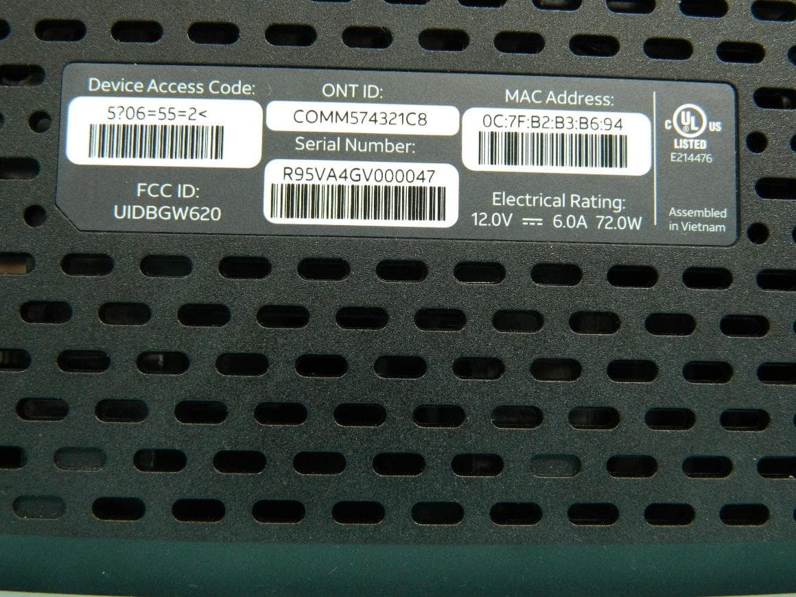
G95BGW620
Aug 26, 2024Wi-Fi 7 XGS-PON Gateway
Equipment Class
NII - Unlicensed National Information Infrastructure TX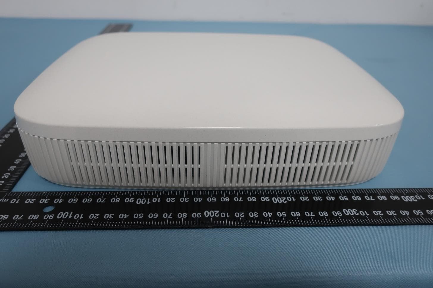
G954981X2
Jan 10, 2024DOCSIS 3.1
Equipment Class
NII - Unlicensed National Information Infrastructure TXG95OWA7111
Jul 20, 2023Wi-Fi 6E Extender
Equipment Class
6PP - 15E 6 GHz Subordinate Indoor Device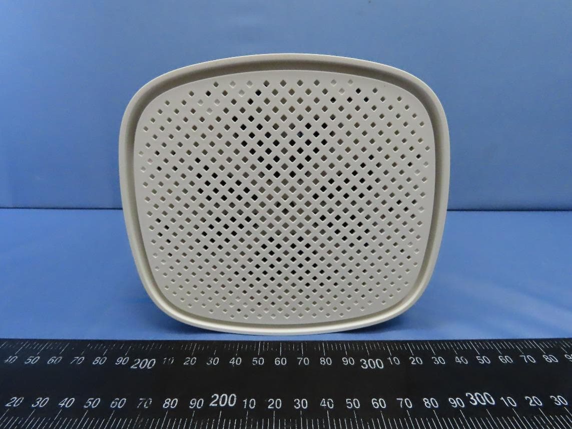
G95EWM322T
Jul 17, 2023Wireless Access Point
Equipment Class
DTS - Digital Transmission System
G95-CGA437T
Jan 14, 2023DOCSIS 3.1 Residential Voice Gateway
Equipment Class
NII - Unlicensed National Information Infrastructure TX