G95TCA200Touch Screen Alarm Panel
Vantiva USA LLC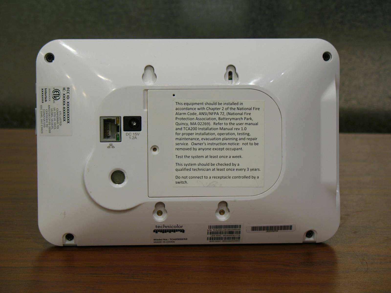
Click to zoom
Application Details
- Equipment Class
- PCB - PCS Licensed Transmitter
- Date of Grant
- Oct 26, 2011
- Application Purpose
- Original Equipment
- Date of Application
- Oct 26, 2011
- Equipment Note
- Touch Screen Alarm Panel
- Frequency Range
- 1850.00000000 - 1910.00000000
- Company
- Vantiva USA LLC
- Country
- United States
Documents & Files
Document Text
Text extracted from the exhibit documents filed with the FCC. Open a document above to read the original.
Users Manual
HomeSystemInstallation Guide TechnicolorTCA200 Release3.8GrenadaSU1 2 Copyright©2011iControlNetworksAllrightsreserved. Noreproductioninwholeorinpartwithoutpriorwrittenapproval.iControlNetworks,iControl,and iControllogodesignarependingtrademarksofiControlNetworks.Allothertrademarksaretheproperty oftheirrespectiveowners.Informationcontainedhereinissubjecttochangewithoutnotice.Theonly warrantiesforiControlproductsandservicesaresetforthintheexpresswarrantystatements accompanyingsuchproductsandservices.Nothinghereinshouldbeconstruedasconstitutingan additionalwarranty.iControlNetworksshallnotbeliablefortechnicaloreditorialerrorsoromissions containedherein.Allrightsreserved. Audience ThisguideisintendedforpeoplewhowanttousetheSubscriberPortal>toaccesstheirTouchScreen settingsandmonitortheirlocation. TypographicConventions Thisdocumentusesthefollowingtypographicconventionstohelpyoulocateandidentifyinformation: ItalictextIdentifiesnewterms,emphasis,andbooktitles BoldtextIdentifiesbuttonnamesandotheritemsthatyoucanclickortouchinthegraphical userinterfaceorpressonacomputerkeyboard Note:Notesprovideextrainformationaboutatopicthatisgoodtoknowbutnotessentialtothe process. CAUTION:Cautionsdrawyourattentiontoactionsthatcouldcompromisethesecurityofyoursystem orresultinthelossofdata. HomeSystemInstallationGuide Overview 3 Overview Tosetupthesecuritysysteminacustomerpremises: 1.CompleteaHomeSecuritySurvey(HSS)forthecustomer. 2.EnsurethecustomerpremisehasaccesstotheInternet. 3.ActivatetheTouchScreen(seeInstallingtheSecuritySystemonpage5). TheTouchScreencanconnecttothemanagedrouter/modemeitherwirelesslyorbyEthernetcable.The TouchScreencommunicateswithsensorsbyradiofrequency.Optionalcamerascommunicatewiththe securitynetworkrouterwirelessly.TheTouchScreenmaintainscommunicationwiththesystemservers throughtheInternetandbyCellular. ThesecuritynetworkrouterMUSTbeinstalled“infront”ofallotherhomenetworksrelativetothe Internet.Connectthecustomer’shomenetworktotheInternetthroughthesecuritynetworkrouterby Ethernetcableasdescribedonpages14and16).Thecustomercaninstallaretailrouterbehindthe securitynetworkrouterandaccesstheInternet.Thecustomercanchoosetoexposetheirretailrouterto theInternetthroughtheDMZofthesecuritynetworkrouterasdescribedintheTouchScreenUser Guide. AMAXIMUMofsixIPcamerasand31ZigBeedevicesaresupportedforthesystem.ZigBeedevices consistofanythingthatcommunicatewiththeTouchScreenoverRadioFrequency,suchas Door/Windowsensorsandsmokedetectors. Figure1:HomeSecurityConfiguration 4 InstallationTools Thefollowingarethetoolsrequiredtoinstallthesecuritysystem: Digitalmulti-meter Rubbingalcoholwithcontainerto dilutewithwater Papertowels Dropclothforworkarea Ladder6’ Compressedairandsoft-bristled Assortedscrewdrivers Soundsensortesterfortestingglass breaksensors Aerosolsmoketester Double-sidedstickytape Alternativedouble-sidedstickytape Tapemeasure Pocketlevel Multi-purposescissors Flashlight Shoecovers Ethernetcableofsufficientlength (usedtoconfigurethecameraor iftheTouchScreenwillnotconnecttothe router/modemwirelessly) HomeSystemInstallationGuide InstallingtheSecuritySystem 5 InstallingtheSecuritySystem Installingthesecuritysysteminthecustomer’shomeconsistsofthefollowinggeneralprocesses.These processesaredetailedinthefollowingpagesofthissection: A.Settingupthe Router(page6) B.InstallingtheTouchScreen(page7) C.EnsureyourTouchScreenConfigurationInformationisCorrect(page11) D.ActivatingtheSystem(page13) E.AddingSensors(page22) F.TestingtheAlarmFunctionalityoftheSecuritySystem(page30) G.SettingandValidatingtheSecurityInformation(page34) H.MountingtheSensors(page38) I.ActivatingtheSubscriberPortal(page38) J.ConfiguringtheTouchScreen(page39) 6 StepA:SettinguptheRouter 1.EnsurethecustomerpremiseshaveaccesstotheInternet. 2.Resetthehomenetworkrouter. Note:Dothis,also,ifyouarerestartingtheinstallationprocessafterhavingestablishedthe connectionbetweentheTouchScreenandtherouter. HomeSystemInstallationGuide InstallingtheSecuritySystem 7 StepB:InstallingtheTechnicolorTouchScreen Note:TomounttheTouchScreenonawall,performtheproceduredescribedonpage79. 1.RemovetheTouchScreenfromitspackaging. 2.UseaP1Phillipsscrewdrivertoremovethe(1) screwfromthebatterycoveroftheTouch- Screen,anddetachthecover. The4.0voltlithiumpolymerbatteryis wrappedandunconnectedinthebattery compartmentoftheTouchScreen. 3.Unwrapthebatteryfromitspackagingandinstallitinthebatterycompartment. 4.Positionthebatteryandcablesinsidethebatterycom- partmentsothecablesliealongthetopofthebattery. 5.Alignandconnectthebattery’spinstothebatterycon- nectorsothatthewireorderis(left-to-right)RED, WHITE,BLACK. 6.Replacethebatterycoverandthescrew. 7.PlacetheDCpowercableintotheclampoftheTouchScreenstand. 8 8.ConnecttheDCadaptercableto thebackoftheTouchScreen. 9.ConnectthestandtothebackoftheTouchScreen.InsertthelongestpegintotheTamperSwitch hole,whichisthetoprightholeonthebackoftheTouchScreen. HomeSystemInstallationGuide InstallingtheSecuritySystem 9 10.PositiontheTouchScreennearanun-switchedwalloutlet(notcontrolledbyalightswitch). 10.IftheinstallationplandoesnotinvolvetheTouchScreenconnectingtothecustomer’snetwork wirelessly,thenconnectanEthernetcabletotheTouchScreenandtheiControl-dedicatedrouter. 11.InserttheA/Cadapterintothebracketas shown. Table1:A/CPowerSupplyRatings RatingValue Voltage100-240V Current0.5A Power Frequency50/60Hz 10 12.Removethecenterscrewfromthewalloutlet. 13.PlugtheTouchScreen’sA/CadapterintotheTOPplugofthe walloutlet,andreplacethecenterscrewthroughthebracket hole. Note:IftheTouchScreendoesnotdisplaytheInstallationWelcomescreen,youmustresetitto factorydefault(seepage51). Afterafewseconds,theInstallationWelcomescreenisdisplayedontheTouchScreen. Figure2:Activation:InstallationWelcomeScreen Note:IftheTouchScreendoesnotdisplaytheInstallationWelcomescreen,youmustresetitto factorydefault(seepage51). HomeSystemInstallationGuide InstallingtheSecuritySystem 11 StepC:EnsureYourTouchScreenConfigurationInformationIsCorrect 1.EnsureyouhavethefollowinginformationfromCustomerCar…
Text truncated - open the document above for the full version.
Users Manual
TouchScreenQuickStartGuide TechnicolorTCA200 Release3.8Grenada Rev3.8GrenadaSU1 August27,2011 ©2006,2007,2008,2009,2010,2011iControlNetworks,Inc.,theiControllogo,uControl,Inc.theuControllogo,OpenHome, andConvergeandallotheruControlproductsandtechnologynamesaretrademarksorregisteredtrademarksofiControl Networks,Inc.Allotherproductsorservicesmentionedhereinaretrademarksoftheirrespectivecompanies. 2 Compliances FCCNotice Thisdevicehasbeendesigned,constructed,andtestedforcompliancewithFCCRulesthatregulateintentionaland unintentionalradiators.Astheuserofthisdevice,youarenotpermittedtomakeanyalterationsormodificationstothis equipmentortouseitinanywaythatisinconsistentwiththeinformationdescribedinthisguide,withouttheexpresswritten permissionofTechnicolor.Doingsowillvoidyourauthoritytooperatethisequipment. ThisdevicecomplieswithFCCRulesPart15andIndustryCanadaRSS-210.Operationissubjecttothefollowingtwoconditions: 1.Thisdevicemaynotcauseharmfulinterference 2.Thisdevicemustacceptanyinterference,includinginterferencethatmaycauseundesiredoperationofthedevice CetappareilestconforméauxFDDrègleslapartie15etRSS-210d’IndustrieCanadaapplicablesauxappareilsradioexempts delicence.L’exploitationestautoriséauxdeuxconditionssuivantes: 1.L’appareilnedoitpasproduiredebrouillage,et 2.L’appareildoitacceptertoutbrouillageradioélectriquesubi,mêmesilebrouillageestsusceptibled’encompromettre lefonctionnement. ThisClassBdigitalapparatuscomplieswithCanadianICES-003. CetappareilnumériquedelaclasseBestconformeàlanormeNMB-003duCanada. RFExposureinformation:Thisdeviseisonlyauthorizedforuseinamobileorfixedapplication.Atleast20cm(8inches)of separationdistancebetweenthetouchscreenandtheuser’sbodymustbemaintainedatalltimestoensurecompliancewith theFCCandIndustryCanadaRFExposureRequirements. Informationsd'expositionauxRF:Cetappareilestuniquementpouruneutilisationdansuneapplicationmobileoufixe.Au moins20centimètresdedistancedeséparationentrel’écrantactileetlecorpsdel’utilisateurdoitêtremaintenueentout tempspourassurerlaconformitéaveclesexigencesdelaFCCetIndustrieCanada,l’exposition. DevicePurpose Fire/AlarmCentralPanel ULandULCNotices ThisdevicecomplieswithUL985,UL1023,UL1635,ULCS545,ULCC1023. LimitationsofSecurityProducts Securityproductsandalarmsystemsdonotofferguaranteedprotectionagainstburglary,fire,orotheremergencies.Theymay failtowarnfordiversereasons,including(butnotlimitedto):powerfailure,deadbatteries,improperinstallation,coverage, coverageareasoverlookedduringinstallation,defeatbytechnicallysophisticatedintruders,componentfailure,orinadequate maintenance.Alarmsystemsshouldbecheckedweeklytoensurethatalldevicesareworkingproperly. ANALARMSYSTEMISNOTASUBSTITUTEFORINSURANCE. TouchScreenQuickStartGuide UsingtheTouchScreen 3 UsingtheTouchScreen TheTechnicolorTCA200TouchScreenisthecenterofyourhomesecuritysystem.ThisAndroid-powered deviceallowsyoutoperformactionssucharminganddisarmingyoursecuritysystem,monitoringthe statusofyoursecuritysensors,andsendingemergencyalarms. Note:ThisQuickStartGuideprovidesanoverviewoftheTouchScreenanditsbasicoperation.This guideassumestheTouchScreenhasbeenactivatedandyouhavebeenassignedasecurity code.Formoreinformation,seetheTouchScreenUser'sGuideandtheHome System InstallationGuide.Thelatestversionscanbefoundat http://www.icontrol.com/support/manuals/technicolor/3_8_Grenada_TouchScreen_User_ Guide_Technicolor.pdfandhttp://www.icontrol.com/support/manuals/technicolor/3_8_ Grenada_Home_Installation_Technicolor.pdf FordetailedinformationaboutoperatinganAndroiddevice,refertotheAndroid documentationprovidedbyGoogle. Warning:TherechargeablebatterythatcamewithyourTouchScreenisonlyavailablethroughyour serviceoperator.Ifyourbatteryneedstobereplaced,contactyourserviceoperatortoarrangefor replacement. ThefollowingdiagramshowsthemajorcomponentsoftheTouchScreen: 4 Eachbuttonisdescribedinthefollowingtable: ButtonDescription Homebutton.PressthisbuttontogototheHome(main)screenintheTouchScreenscreen. Androidmenubutton.PressthisbuttontodisplaytheAndroidconfigurationmenu. Backbutton.Pressthisbuttontoreturntothepreviousscreen. EmergencyAlarmbutton.Pressthisbuttontomanuallyandimmediatelysendanalarmto theappropriatecallcenter.Thebuttonislocatedatthebottomrightinfrontofthedevice. WhenA/Cpowerisavailable,thisbuttonislit.Seepage10formoreinformation. UnderstandingtheScreen TheTouchScreencommunicateswithyoursecuritysystem.Itcombinessecurityandhomecontrolsona graphicalinterface,providing: Areal-timeviewofthesystemstatuses Toolstomanageyoursecuritysystem Additionaloptionalapplicationssuchasnewsandweather ThefirstscreendisplayedistheHomescreen.Itisfromthisscreenthatyounavigatethroughmenusby tappingbuttonstoaccessthefunctionyoudesire.Ifthescreenisblack(showingnothing)thisisbecause thesystemisnotreceivingA/Cpowerorthedisplayispoweredofftoconservebatterylife. Thescreenisdividedintothefollowingoperationalsections: SecurityStatusHeader System&ZoneTroubleHeader ContentArea SecurityStatusHeader TheSecurityStatusheaderdisplaysintheupperlefthandoftheTouchScreen.Ittellsyouwhetherthe systemisarmedordisarmedandotherinformation.Tapthisheadertoarmordisarmthesystem. Also,duringtroublesthatwouldpreventarming(suchasamonitoreddoororwindowbeingopened)an announcementreplacestheArm/Disarmstatus. TouchScreenQuickStartGuide UsingtheTouchScreen 5 DuringtheExitDelay,theheaderchangestoannouncethenumberofsecondsuntilthesystemisarmed. DuringtheEntryDelay,theheaderchangestoannouncethenumberofsecondsbeforethealarm sounds. System&ZoneTroubleHeader TheSystem&ZoneTroubleheaderdisplaysintheupperrighthandoftheTouchScreen.Itonlydisplays whenthereisaconnectivity(cellular,broadband,etc.)orpowerproblemwiththeTouchScreen,whena sensorgoesdown(suchasduetoabatteryfailure),orasensorisbeingtamperedwith(suchasthecover beingopened). Whenthesystemreportsatrouble,itsoundsanaudiblealertregularlytoensurethatyouareawareof theproblem. WhenaSystem&Zoneheaderisdisplayed,tapittoshowtheTroubleslistwhichdisplaysallthecurrent troubleswiththeTouchScreenandsensors. ContentArea TheContentar…
Text truncated - open the document above for the full version.
Users Manual
TouchScreenUser'sGuide TechnicolorTCA200 Release3.8Grenada PN:631-00008-01Rev3.8GrenadaSU1 August4,2011 2 ©2006,2007,2008,2009,2010,2011iControlNetworks,Inc.,theiControllogo,uControl,Inc.the uControllogo,OpenHome,andConvergeandallotheruControlproductsandtechnologynamesare trademarksorregisteredtrademarksofiControlNetworks,Inc.Allotherproductsorservicesmentioned hereinaretrademarksoftheirrespectivecompanies. Compliances FCCNotice Thisdevicehasbeendesigned,constructed,andtestedforcompliancewithFCCRulesthatregulate intentionalandunintentionalradiators.Astheuserofthisdevice,youarenotpermittedtomakeany alterationsormodificationstothisequipmentortouseitinanywaythatisinconsistentwiththe informationdescribedinthisguide,withouttheexpresswrittenpermissionofTechnicolor.Doingsowill voidyourauthoritytooperatethisequipment. ThisdevicecomplieswithPart15oftheFCCrules.Operationofthisdeviceissubjecttothefollowingtwo conditions: 1.Thisdevicemaynotcauseharmfulinterference,and 2.Thisdevicemustacceptanyinterferencereceived,includinginterferencethatmaycauseunde- siredoperation. The“IC”designationprecedingtheradiocertificationnumberindicatesthatthisdevicecomplieswiththe IndustryofCanadaspecifications. DevicePurpose Fire/AlarmCentralPanel UL1023Notice ThisdevicecomplieswithUL1023. UL985Notice ThisdevicecomplieswithUL985. TouchScreenUser'sGuide 3 UL1635Notice ThisdevicecomplieswithUL1635. ULCS545Notice ThisdevicecomplieswithULCS545. ULCC1023Notice ThisdevicecomplieswithULCC1023. ETLNotice ThisdevicecomplieswithallETLandETLCsafetyrequirements. InsertcopyofETLstickerwhenavailable LimitationsofSecurityProducts Securityproductsandalarmsystemsdonotofferguaranteedprotectionagainstburglary,fire,orother emergencies.Theymayfailtowarnfordiversereasons,including(butnotlimitedto):powerfailure,dead batteries,improperinstallation,coverage,coverageareasoverlookedduringinstallation,defeatby technicallysophisticatedintruders,componentfailure,orinadequatemaintenance.Alarmsystems shouldbecheckedweeklytoensurethatalldevicesareworkingproperly. ANALARMSYSTEMISNOTASUBSTITUTEFORINSURANCE. 4 Contents Compliances2 DevicePurpose2 UL1023Notice2 UL985Notice2 UL1635Notice3 ULCS545Notice3 ULCC1023Notice3 ETLNotice3 LimitationsofSecurityProducts3 WelcometotheTouchScreen6 UnderstandingSecurityNetworkComponents7 UnderstandingtheSecurityZoneTypes8 UnderstandingAlarms9 ConfiguringtheTouchScreen9 SubscriberPortal10 UsingtheTouchScreen11 UnderstandingtheTouchScreenControls11 UnderstandingtheScreen12 SecurityStatusHeader12 System&ZoneTroubleHeader13 ContentArea18 LowPowerMode19 ManagingYourSystemSecurity21 UnderstandingArmingModes21 ArmAwayMode21 ArmStayMode22 ArmNightMode23 UnderstandingYourProtectionAgainstSmash&GrabAttacks23 ArmingandDisarmingtheSystem23 DisarmingtheSystem&UnderstandingWhatHappensDuringanAlarm23 TodisarmthesystemfromtheTouchScreen:25 ArmingtheSystem26 SendinganEmergencyAlarm28 ManagingSensors29 DisableaSensor30 ViewingYourZoneEventHistory30 ChangingtheOrderthatSecurityZonesareListedintheTouchScreen31 TestingYourAlarms32 ManagingConnectivityBetweentheTouchScreenandtheCentralMonitoringStations35 ViewingSignalStrength35 TestingYourConnectivity.36 ManagingthePasscodesinyourSecuritySystem36 ManagingyourKeypadCodes37 ManagingYourSecretWord39 ViewYourSecurityAccountInformation39 Maintaining&ConfiguringtheTouchScreenDevice40 TouchScreenUser'sGuide 5 ReboottheTouchScreen40 UnderstandingandConfiguringScreenBrightness&ScreenDimming40 ConfiguringtheScreensaver44 ConfiguringtheTonesandVolumeLevels45 CleaningtheTouchScreenScreen46 ViewingTechnicalSpecificationsofYourTouchScreen47 Appendix1:TouchScreenInstallationandMaintenance48 InstallingtheTechnicolorTouchScreen48 BatteryRequirements52 ReplacingtheBattery52 RecommendationsforSensorInstallationandPlacement54 SystemLimitations56 EmergencyPreparations57 AppendixD:QuickReferenceTables59 6 WelcometotheTouchScreen ThepurposeofthisdocumentistoexplainthefollowingintheOpenHomeConvergesystem: UnderstandandoperatetheTouchScreendevice Armanddisarmyoursecuritysystem Sendapanicalarm Viewsystemstatusandarm/disarmthesystem ManageconnectivitybetweentheTouchScreenandtheCentralMonitoringStations Managepasscodes Managesecurityzones Manageemergencydispatchcontactinformation Viewhistorylogs Viewaccountinformation Figure1:SecurityNetwork TouchScreenUser'sGuide WelcometotheTouchScreen 7 UnderstandingSecurityNetworkComponents SecurityNetworkComponentsdescribestheequipmentincludedwithyoursecuritysystem. Table1:SecurityNetworkComponents ComponentDescription TouchScreenThedeviceusedtointerfacewithyoursecuritysystem. SensorsDoorway/windowMonitorstheopeningandclosingofpotentialentryandexit points. Motion(indoor)Monitorsmovementwithinthepremises SecurityNet- workRouter Thehubofyoursecuritynetwork.Thisdeviceisinstalledbetweenyourbroadband modemandyourhomenetworkrouter. SmokeDetectorThisdevicesoundsanalarmwhensmokeisdetected. 8 UnderstandingtheSecurityZoneTypes Securityzonesarethesensorsthatdetectmovementandtheopeningandclosingofdoorsand windows.ThesensorscommunicatewirelesslywithyourTouchScreen.Securityzonesareaddedtothe systemandconfiguredbyyourinstaller.Youcanenableanddisableeachsecurityzoneusingthe Securitywidget. Security Zone Function DescriptionSensorTypes Entry/exitFordoorwaysthatareusedtoenterthepremises. Whenthesystemisarmed,faultingthistypeofsensorstartsanEntry Delaycountdownratherthansendinganimmediatealarm. DuringExitDelay,thiszonecanberepeatedlyfaulted.Doorwayscanbe configuredtobeentry/exitornon-entry/exit. Note:FormoreinformationonEntry/Exitdelays,see"Managing YourSystemSecurity"onpage21 Door/Window PerimeterIffaultedwhenthesystemisarmedorduringanEntry/Exitdelay,an alarmistripped. Door/Window sensor Motion detector Glassbreak detector Interior Follower Monitorstheinternallivingspacesofthepremisesandtriggersan immediatealarmifthesystemisarmedinAwaymode. NotarmedwhenthesystemisinArmedStaymode. Motiondetec- tor 24-Hour Inform Whenthissecurityzoneistripped,thereisneveranalarm.However, aneventisrecordedinthehistory,…
Text truncated - open the document above for the full version.
ID Label/Location Info
Model: TCA200GEN Date: label base Notes:1.Surface material: 25#M YLAR, thickness 0.025mm 2.Background co lor: white. 3.Adhesive thickn ess 0.025+/-0.002mm. 4.Liner: Glassine5.printing color: black6.The material must be RoHS compliant7. The label supplier MUST assu re that labels meet UL requirements (ETI ‐ 01 IN PGDQ2.MH45260 for supplier of ETI) 2011.07.18 Label Spec - Safety label Model: TCA200GEN Date: 2011.07.18 Label Spec - UL985 required label Notes:1.Surface material: 50#MY LAR, thickness 0.05+/ ‐ 0.005mm 2.Background color: white.3.Adhesive thickness 0.025+/ ‐ 0.002mm. 4.Liner: Glassine5.printing color: black6.The material must be RoSH compliant 7. The label supplier MUST assure that labels meet UL requirements ( ETI ‐ 01 in PGDQ2.MH45260 for supplier of ETI) label base Model: TCA200GEN Date: 1.SN detail defineSN Format : S/N: MMMVVVYWWCCHFXXXXXXMMM: product model (TCA)VVV: Product version (200)Y: production yearWW: production weekCC: customer ID (00:GEN black version)H: HW versionF: production facility (1: Foxconn)XXXXXX: sequential code,from 000000 ‐ 999999 Remark: Sequential code Will be continuous andnever be reset unless out of range.SN barcode type: code 128SN barcode height: 3mmSN font type : Calibri , 1.3mmThere must be a blank after":" 3:MADE IN CHINAfont: Calibri,1.5mm4. MODEL:TCA200GEN font: calibri bold,1.5mm 2.LAN MAC and WIFI MAC detail defineLAN MAC: XXXXXXXXXXXXXXWIFI MAC: XXXXXXXXXXXXMac Range get from TechnicolorGCD MAC address rangeMAC barcode type: code 128MAC barcode height: 3mmMAC font: Calibri, 1.3mmThere must be a blank after":" 2011.07.18 Label Spec - Product label Notes:1.Surface material: 25#M YLAR, thickness 0.025mm 2.Background color: white.3.Adhesive thickness 0.025+/-0.002mm.4.Liner: Glassine5.printing color: black6.The material must be RoHS compliant 7. The label supplier MUST assure that labels meet UL requirements (ETI ‐ 01 IN PGDQ2.MH45260 for supplier of ETI) Model: TCA200GEN Date: Housing labels location 2011.07.18 Model: TCA200GEN Date: Label Spec - Gift box label 1.SN detail defineSN Format : S/N: MMMVVVYWWCCHFXXXXXXMMM: product model (TCA)VVV: Product version (200)Y: production yearWW: production weekCC: customer ID (00:GEN black version)H: HW versionF: production facility (1: Foxconn)XXXXXX: sequential code,from 000000 ‐ 999999 Remark: Sequential code Will be continuous andnever be reset unless out of range.SN barcode type: code 128SN barcode height: 4mmSN font type : Calibri , 1.5mmThere must be a blank after":" 3:MADE IN CHINAfont: Calibri,1.5mm4. MODEL:TCA200GEN font: calibri bold,1.5mm 2.LAN MAC and WIFI MAC detail defineLAN MAC: XXXXXXXXXXXXXXWIFI MAC: XXXXXXXXXXXXMAC Range is provide by TechnicolorMAC barcode type: code 128MAC barcode height: 4mmMAC font: Calibri, 1.5mmThere must be a blank after":" 2011.07.18 Model: TCA200GEN Date: Label Spec - Carton label 2011.07.18
Internal Photos
PHOTOS: External front and back, PCB both sides with and without shields
RF Exposure Info
731 Enterprise Drive Lexington, KY 40510 Telephone: 859-226-1000 Facsimile: 859-226-1040 www.intertek-etlsemko.com MPE Calculation § 1.1310: The criteria listed in table 1 shall be used to evaluate the environmental impact of human exposure to radiofrequency (RF) radiation as specified in §1.1307(b), except in the case of portable devices which shall be evaluated according to the provisions of §2.1093 of this chapter. Part 1.1310 Limits for Maximum Permissible Exposure (MPE) 1.1 Test Procedure An MPE evaluation for was performed in order to show that the device was compliant with §2.1091. The maximum power density was calculated for each transmitter at a separation distance of 20cm. For each transmitter the maximum RF exposure at a 20 cm distance using the formula: 10/)( 10 dBmowerConductedP mW PowerConducted= 2 )20(4 . cm mW GainAntPowerConducted tyPowerDensi × × = π 731 Enterprise Drive Lexington, KY 40510 Telephone: 859-226-1000 Facsimile: 859-226-1040 www.intertek-etlsemko.com 1.2 Results: The device contains Cellular, Zigbee, and 802.11 transmitters which can transmit simultaneously. The following calculations show that the total power density from each transmitter at 20cm is less than the limit for general population / un-controlled exposure. With the Cellular, 802.11, and Zigbee modules transmitting simultaneously, the worse case MPE calculations are less than 20% of the applicable limit. The device meets the RF exposure limit at a 20cm separation distance as required by part 2.1091 of the FCC rules with all modules transmitting simultaneously. Burst Average Conducted Output Power of Cellular Module BandChannel Frequency (MHz) GSM GPRS - 1 Tx Slot GPRS - 2 Tx Slots GPRS - 3 Tx Slots GPRS - 4 Tx Slots EDGE - 1 Tx Slot EDGE - 2 Tx Slots EDGE - 3 Tx Slots EDGE - 4 Tx Slots 128824.232.85 33 31.3429.5727.4527.6625.523.621.6 190836.632.7532.8931.2629.4727.3627.6225.4523.6121.57 251848.832.6132.731.1329.3627.2427.4925.3623.4121.49 5121850.229.23 29.3 27.2425.4423.6225.223.4121.619.77 661188029.0329.1727.0725.2723.4724.9923.2221.4319.59 8101909.828.828.926.9425.0423.2224.8123.0221.2219.33 GSM 850 GSM 1900 Time Average Conducted Output Power of Cellular Module (Duty Cycle (10*Log(Tx Slots/8) Included) BandChannel Frequency (MHz) GSM GPRS - 1 Tx Slot GPRS - 2 Tx Slots GPRS - 3 Tx Slots GPRS - 4 Tx Slots EDGE - 1 Tx Slot EDGE - 2 Tx Slots EDGE - 3 Tx Slots EDGE - 4 Tx Slots 128824.223.8223.97 25.32 25.3124.4418.6319.4819.3418.59 190836.623.7223.8625.2425.2124.3518.5919.4319.3518.56 251848.823.5823.6725.1125.1024.2318.4619.3419.1518.48 5121850.220.2020.27 21.22 21.1820.6116.1717.3917.3416.76 661188020.0020.1421.0521.0120.4615.9617.2017.1716.58 8101909.819.7719.8720.9220.7820.2115.7817.0016.9616.32 GSM 850 GSM 1900 Test Summary GSM 850 Band Transmitter: Frequency 824.2 MHz Limit 0.549 mW/cm^2 Distance 20 cm Power 25.32 dBm TX Ant Gain -0.12 dBi EIRP 25.2 331.1311 mW Power Density 0.0659 mW/cm^2 at 20cm % of MPE Limit 11.99 GSM 1900 Band Transmitter: Frequency 1850.2 MHz Limit 1.000 mW/cm^2 Distance 20 cm Power 21.22 dBm TX Ant Gain 2.09 dBi EIRP 23.31 214.2891 mW Power Density 0.0426 mW/cm^2 at 20cm % of MPE Limit 4.26 802.11 Frequency 2412 MHz Limit 1.000 mW/cm^2 Distance 20 cm Power 17.71 dBm TX Ant Gain 1.87 dBi EIRP 19.58 90.78205 mW Power Density 0.0181 mW/cm^2 at 20cm % of MPE Limit 1.81 Zigbee Transmitter Frequency 2450 MHz Limit 1.000 mW/cm^2 Distance 20 cm Power 18.87 dBm TX Ant Gain 1.92 dBi EIRP 20.79 119.9499 mW Power Density 0.0239 mW/cm^2 at 20cm % of MPE Limit 2.39
Test Report
This report is for the exclusive use of Intertek's Client and is provided pursuant to the agreement between Intertek and its Client. Intertek's responsibility and liability are limited to the terms and conditions of the agreement. Intertek assumes no liability to any party, other than to the Client in accordance with the agreement, for any loss, expense or damage occasioned by the use of this report. Only the Client is authorized to permit copying or distribution of this report and then only in its entirety. Any use of the Intertek name or one of its marks for the sale or advertisement of the tested material, product or service must first be approved in writing by Intertek. The observations and test results in this report are relevant only to the sample tested. This report by itself does not imply that the material, product, or service is or has ever been under an Intertek certification program. EMC Report for Technicolor USA, Inc. on the Wireless Control Tablet Page 1 of 48 731 Enterprise Drive Lexington, KY 40510 Telephone: 859-226-1000 Facsimile: 859-226-1040 www.intertek-etlsemko.com TEST REPORT Report Number: 100350432LEX-001 Project Number: G100350432 Report Issue Date: 9/12/2011 Product Name: Wireless Control Tablet Model Number: TCA200 FCCID: G95TCA200 ICID: 431C-TCA200 FCC Standards: FCC Part 22 Subpart H FCC Part 24 Subpart E Industry Canada Standards: RSS-132 Issue 2 RSS-133 Issue 5 Tested by: Client: Intertek Testing Services NA, Inc. 731 Enterprise Drive Lexington, KY 40510 Technicolor USA, Inc. 101 W 103rd Street Indianapolis, IN 46290 Report prepared by Report reviewed by Jason Centers, Senior Project Engineer Yuriy Litvinov, EMC Business Manager Intertek Report Number: 100350432LEX-001 Issued: 9/12/2011 EMC Report for Technicolor USA, Inc. on the Wireless Control Tablet FCCID:G95TCA200 Page 2 of 48 TABLE OF CONTENTS 1 Introduction and Conclusion .............................................................................................................. 3 2 Test Summary ...................................................................................................................................... 3 3 Description of Equipment Under Test ............................................................................................... 4 4 Conducted Output Power.................................................................................................................... 7 5 Occupied Bandwidth ......................................................................................................................... 10 6 Conducted Spurious Emissions at Antenna Terminals ................................................................. 13 7 Radiated Output Power ..................................................................................................................... 35 8 Radiated Spurious Emissions (Transmitter) ................................................................................... 36 9 Frequency Stability ............................................................................................................................ 42 10 Measurement Uncertainty.............................................................................................................. 47 11 Revision History ............................................................................................................................. 48 Intertek Report Number: 100350432LEX-001 Issued: 9/12/2011 EMC Report for Technicolor USA, Inc. on the Wireless Control Tablet FCCID:G95TCA200 Page 3 of 48 1 Introduction and Conclusion The tests indicated in section 2 were performed on the product constructed as described in section 3. The remaining test sections are the verbatim text from the actual data sheets used during the investigation. These test sections include the test name, the specified test method, a list of the actual test equipment used, documentation photos, results and raw data. No additions, deviations, or exclusions have been made from the standard(s) unless specifically noted. Based on the results of our investigation, we have concluded the product tested complied with the requirements of the standard(s) indicated. The results obtained in this test report pertain only to the item(s) tested. The INTERTEK-Lexington is located at 731 Enterprise Drive, Lexington Kentucky, 40510. The radiated emission test site is a 10-meter semi-anechoic chamber. The chamber meets the characteristics of CISPR 16-1 and ANSI C63.4. For measurements, a remotely controlled flush-mount metal-top turntable is used to rotate the EUT a full 360 degrees. A remote controlled non-conductive antenna mast is used to scan the antenna height from one to four meters. The test site is listed with the FCC under registration number 485103. 2 Test Summary Page Test full name FCC Reference Industry Canada Result 7 Conducted Output Power §2.1046 §24.232(d) RSS-132 (4.4), RSS-133 (4.1), RSS-133 (6.4) Pass 10 Occupied Bandwidth §2.1049, §22.917(b)(d), and §24.238(a) RSS-GEN (4.6.1), RSS-133 (2.3) Pass 13 Conducted Spurious Emissions §2.1049, §2.1051, §22.917(a)(b), and § 24.238(a)(b) RSS-132 (4.5), RSS-133 (6.5.1) Pass 35 Radiated Output Power § 22.913(a) and § 24.232(c) RSS-132 (4.4), RSS-133 (6.4) Pass 35 Radiated Spurious Emissions (Transmitter) §2.1053, §22.917(a)(b), and §24.238(a)(b) RSS-132 (4.5), RSS-133 (6.5) Pass 42 Frequency Stability §2.1055, §22.355, and §24.235 RSS-132 (4.3), RSS-133 (6.3) Pass 45 Radiated Spurious Emis…
Text truncated - open the document above for the full version.
Contact Information
Applicant
Robert Lyall(Principal Certification Engineer)
Technical Contact
TechnicolorPaul Whereatt
101 West 103rd Street · Indianapolis, Indiana · United States
Test Firm
Intertek Testing Services NAJames Sudduth
Technical Specifications
| # | Rule Parts | Frequency Range | Power Output | Emission | Tolerance |
|---|---|---|---|---|---|
| 4 | 24E | 1.85 GHz - 1.91 GHz | 340.00 mW | 238KG7W | 2 ppm |
Other Applications from Vantiva USA LLC
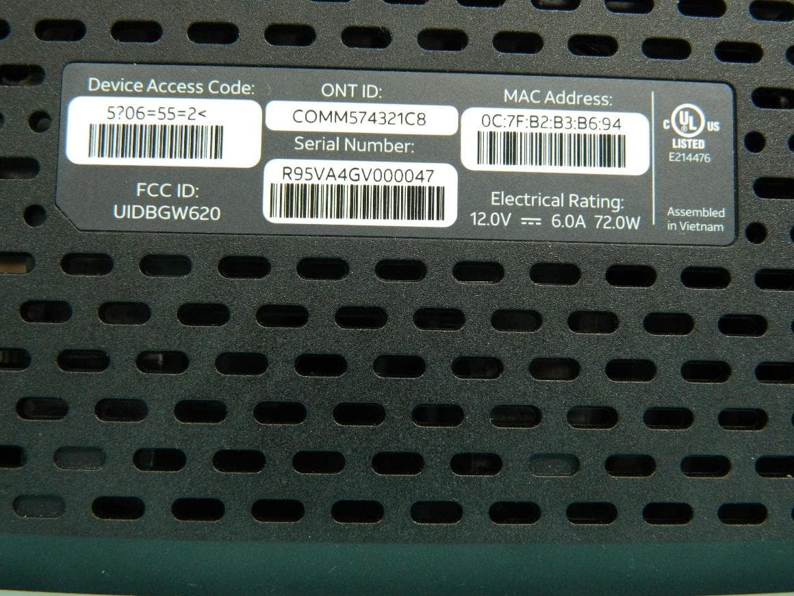
G95BGW620
Aug 26, 2024Wi-Fi 7 XGS-PON Gateway
Equipment Class
NII - Unlicensed National Information Infrastructure TX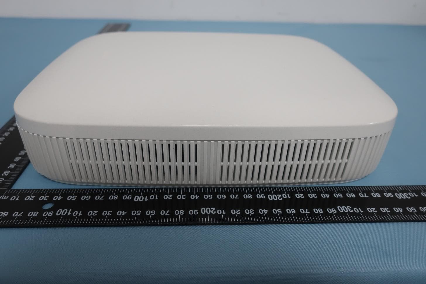
G954981X2
Jan 10, 2024DOCSIS 3.1
Equipment Class
NII - Unlicensed National Information Infrastructure TXG95OWA7111
Jul 20, 2023Wi-Fi 6E Extender
Equipment Class
6PP - 15E 6 GHz Subordinate Indoor Device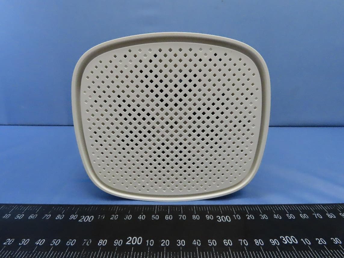
G95EWM322T
Jul 17, 2023Wireless Access Point
Equipment Class
DTS - Digital Transmission System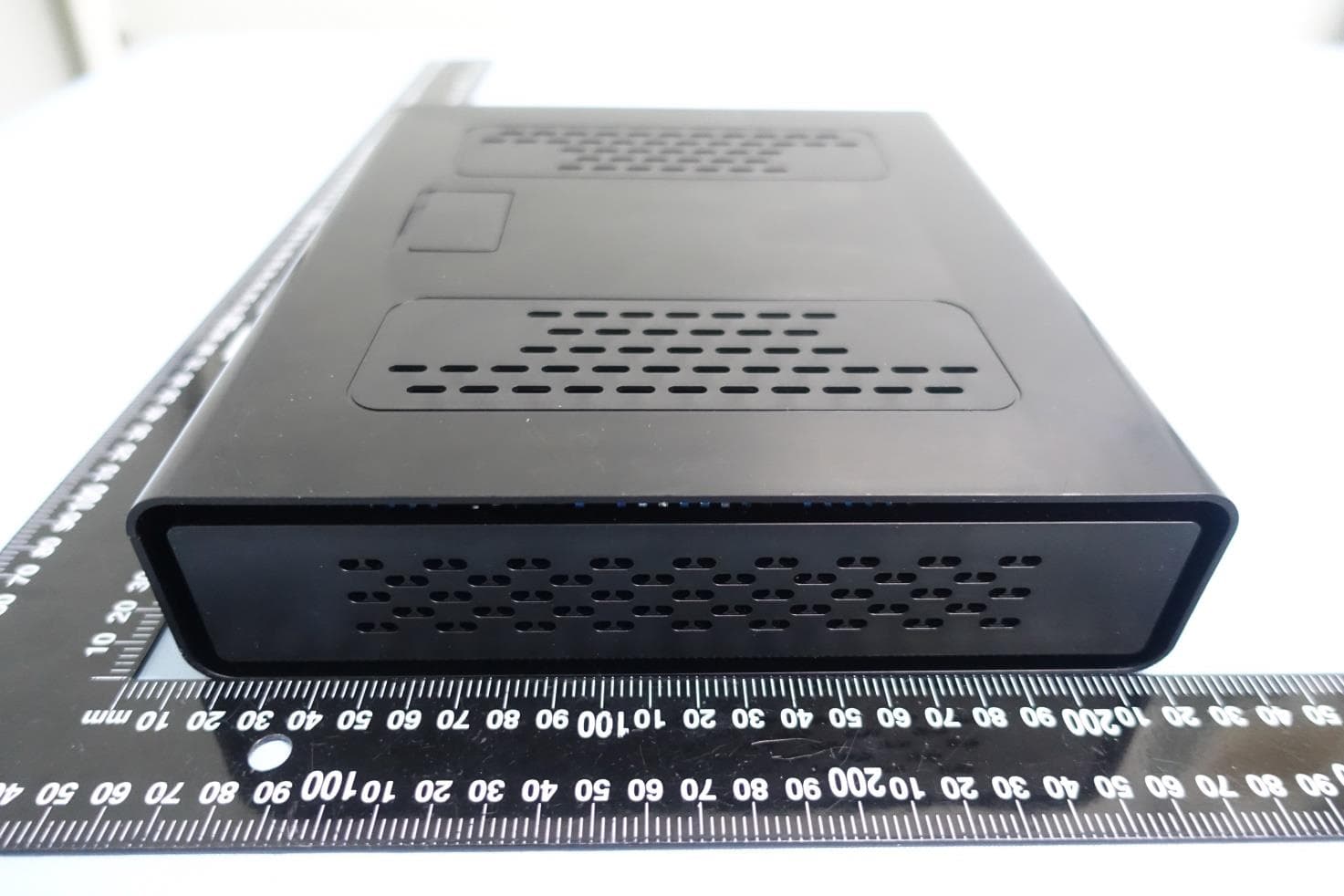
G95-CGA437T
Jan 14, 2023DOCSIS 3.1 Residential Voice Gateway
Equipment Class
NII - Unlicensed National Information Infrastructure TX