G95WMJ900900 MHz wireless modem, model WMJ900
Vantiva USA LLC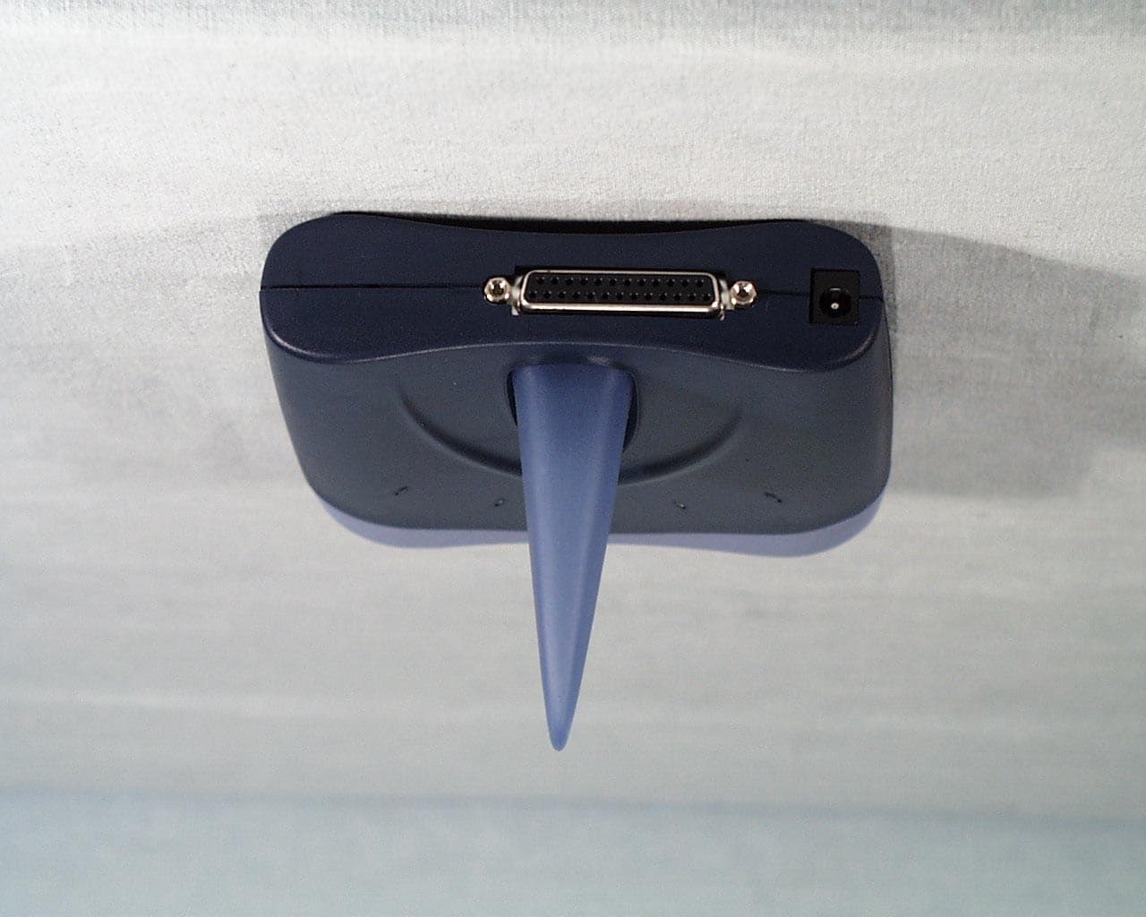
Click to zoom
Application Details
- Equipment Class
- DSS - Part 15 Spread Spectrum Transmitter
- Date of Grant
- May 17, 2001
- Application Purpose
- Original Equipment
- Date of Application
- May 17, 2001
- Equipment Note
- 900 MHz wireless modem, model WMJ900
- Frequency Range
- 905.72800000 - 924.16000000
- Company
- Vantiva USA LLC
- Country
- United States
Documents & Files
Document Text
Text extracted from the exhibit documents filed with the FCC. Open a document above to read the original.
Cover Letter(s)
COMMUNICATION CERTIFICATION LABORATORY TEST REPORT: 73-7464 FCC ID: G95WMJ900 Page 1 Exhibit 13 Exhibit 13 - Request for Confidentiality Letter
External Photos
COMMUNICATION CERTIFICATION LABORATORY TEST REPORT: 73-7464 FCC ID: G95WMJ900 Page 1 Exhibit 3 Exhibit 3: Photographs of Overall Appearance Front View of the Base Unit COMMUNICATION CERTIFICATION LABORATORY TEST REPORT: 73-7464 FCC ID: G95WMJ900 Page 2 Exhibit 3 Back view of the Base Unit COMMUNICATION CERTIFICATION LABORATORY TEST REPORT: 73-7464 FCC ID: G95WMJ900 Page 3 Exhibit 3 Front View of The Extension Unit COMMUNICATION CERTIFICATION LABORATORY TEST REPORT: 73-7464 FCC ID: G95WMJ900 Page 4 Exhibit 3 Back View of the Extension Unit
ID Label/Location Info
COMMUNICATION CERTIFICATION LABORATORY TEST REPORT: 73-7464 FCC ID: G95WMJ900 Page 1 Exhibit 1 Exhibit 1: FCC ID Label Equipment Identification Label In accordance with the requirements of Sections 15.19 (a), 2.925 and 2.926 of the FCC Rules, the following information will be permanently affixed to the Thomson Multimedia Inc. Model WMJ900 as shown in the photograph below. The FCC ID number and the compliance statement are located on both the Base Unit(BU) and the Extension Unit(EU). COMMUNICATION CERTIFICATION LABORATORY TEST REPORT: 73-7464 FCC ID: G95WMJ900 Page 2 Exhibit 1 COMMUNICATION CERTIFICATION LABORATORY TEST REPORT: 73-7464 FCC ID: G95WMJ900 Page 3 Exhibit 1
RF Exposure Info
COMMUNICATION CERTIFICATION LABORATORY TEST REPORT: 73-7464 FCC ID: G95WMJ900 Page 1 Exhibit 11 Exhibit 11 RF Exposure/Environmental Evaluation COMMUNICATION CERTIFICATION LABORATORY TEST REPORT: 73-7464 FCC ID: G95WMJ900 Page 2 Exhibit 11 EIRP = G * Pw EIRP = 1.58 * 0.12 = 0.189 Antenna Gain = 2dBi G = 1.58 Pw = 0.12 watts
Test Report
COMMUNICATION CERTIFICATION LABORATORY TEST REPORT: 73-7464 FCC ID: G95WMJ900 Page 1 Exhibit 6 Exhibit 6: Test Report TEST REPORT FROM: COMMUNICATION CERTIFICATION LABORATORY 1940 W. Alexander Street Salt Lake City, Utah 84119-2039 Type of Report: Certification TEST OF: WMJ900 FCC ID: G95WMJ900 To FCC PART 15.247, Subpart C Test Report Serial No: 73-7464 Applicant: Thomson Multimedia Inc. 10330 North Meridian Street Indianapolis, IN 46290-1024 Date of Test: February 12 & 14, 2001 Issue Date: March 12, 2001 Equipment Receipt Date: February 12, 2001 COMMUNICATION CERTIFICATION LABORATORY TEST REPORT: 73-7464 FCC ID: G95WMJ900 Page 2 Exhibit 6 CERTIFICATION OF ENGINEERING REPORT This report has been prepared by Communication Certification Laboratory to determine compliance of the device described below with the requirements of FCC PART 15.247, Subpart C. This report may be reproduced in full, partial reproduction may only be made with the written consent of the laboratory. The results in this report apply only to the sample tested. - Applicant: Thomson Multimedia Inc. - Manufacturer: Siam United Hitech Ltd. - Brand Name: RCA - Model Number: WMJ900 - FCC ID: G95WMJ900 On this 14 th day of May 2001, I, individually, and for Communication Certification Laboratory, certify that the statements made in this engineering report are true, complete, and correct to the best of my knowledge, and are made in good faith. COMMUNICATION CERTIFICATION LABORATORY Checked by: Anh T. Wride Vice President Tested by: Kirk P. Thomas Project Engineer COMMUNICATION CERTIFICATION LABORATORY TEST REPORT: 73-7464 FCC ID: G95WMJ900 Page 3 Exhibit 6 SECTION 1. CLIENT INFORMATION AND RESPONSIBLE PARTY: 1.1 Client Information: Company Name: Thomson Multimedia Inc. 10330 North Meridian Street Indianapolis, IN 46290-1024 Contact Name: Paul Tinaphong Title: Engineering & QC Manager COMMUNICATION CERTIFICATION LABORATORY TEST REPORT: 73-7464 FCC ID: G95WMJ900 Page 4 Exhibit 6 SECTION 2. EQUIPMENT UNDER TEST (EUT) 2.1 Identification of EUT: Trade Name: RCA Model Name or Number: WMJ900 Serial Number: N/A Options Fitted: None Country of Manufacture: Thailand 2.2 Description of EUT: The WMJ900 is a 900 MHz wireless modem. The WMJ900 consists of a base unit and an extension unit. The base unit provides two telephone ports (1-line, 1-telephone) and an RS232 port. The RS- 232 port is not supported and will be removed in future production models. The Extension unit provides an RS-232 port for connecting to the host computer. In general, the base unit and extension unit are identical except for additional modem function on the base unit. Therefore, the base unit test data is supplied in this report representative of both units. See theory of operation (Exhibit 12). This report covers the transmitter only. The receiver and the digital circuitry are covered under a separate verification report. 2.3 Modification Incorporated/Special Accessories on EUT: There were no modifications or special accessories required to comply with the specification. 2.4 EUT and Support Equipment: The FCC ID numbers for all the EUT and support equipment used during the test (including inserted cards) are listed below: Brand Name Model Number Serial No. FCC ID Number Description Name of Interface Ports/Interface Cables BN: RCA MN: WMJ900 SN: N/A G95WMJ900 Base Unit and Extension Unit (EUT’s) RS232 / 25 pin to 9 pin serial cable RJ11 / 4 conductor phone cable COMMUNICATION CERTIFICATION LABORATORY TEST REPORT: 73-7464 FCC ID: G95WMJ900 Page 5 Exhibit 6 2.5 List of Channels: Channel Number Channel Frequency (MHz) 1 905.728 2 907.776 3 909.824 4 911.872 5 913.920 6 915.968 7 918.016 8 920.064 9 922.112 10 924.160 COMMUNICATION CERTIFICATION LABORATORY TEST REPORT: 73-7464 FCC ID: G95WMJ900 Page 6 Exhibit 6 SECTION 3. TEST SPECIFICATION, METHODS & PROCEDURES 3.1 Test Specification: Title: FCC PART 15.247, Subpart C (47 CFR 15). Limits and methods of measurement of radio interference characteristics of radio frequency devices. Operation within the bands 902-928 MHz, 2400-2483.5 MHz and 5725-5850 MHz. Purpose of Test: The tests were performed to demonstrate Initial compliance. 3.2 Methods & Procedures: 3.2.1 15.247 (a) Operation under the provisions of this section is limited to frequency hopping and direct sequence spread spectrum intentional radiators that comply with the following provisions: (1) Frequency hoping systems shall have hopping channel carrier frequencies separated by a minimum of 25 kHz or the 20 dB bandwidth of the hopping channel, whichever is greater. The system shall hop to channel frequencies that are selected at the system-hopping rate from a pseudorandomly ordered list of hopping frequencies. Each frequency must be used equally on the average by each transmitter. The system receivers shall have input bandwidths that match the hopping channel bandwidths of their corresponding transmitters and shall shift frequencies in synchronization with the transmitting signals. (i) Frequency hopping systems operating in the 902 - 928 MHz band shall use at least 50 hopping frequencies. The maximum allowed 20 dB bandwidth of the hopping channel is 500 kHz. The average time of occupancy on any frequency shall not be greater than 0.4 seconds within a 20 second period. (ii) Frequency hopping systems operating in the 2400 – 2483.5 MHz and the 5725 – 5850 MHz bands shall use at least 75 hopping frequencies. The maximum allowed 20 dB bandwidth of the hopping channel is 1 MHz. The average time of occupancy on any frequency shall not be greater than 0.4 seconds within a 30 second period. COMMUNICATION CERTIFICATION LABORATORY TEST REPORT: 73-7464 FCC ID: G95WMJ900 Page 7 Exhibit 6 (2) For direct sequence systems, the minimum 6 dB bandwidth shall be at least 500 kHz. (b) The maximum peak output power of the transmitter shall not exceed 1 watt. If transmitting antennas of directional gain greater than 6 dBi are used, the power shall be reduced by the amount in dB that…
Text truncated - open the document above for the full version.
Test Setup Photos
COMMUNICATION CERTIFICATION LABORATORY TEST REPORT: 73-7464 FCC ID: G95WMJ900 Page 1 Exhibit 7 Exhibit 7: Test Set-Up Photographs Front View of Worst Case Radiated and Line Conducted Emissions Test Set-up COMMUNICATION CERTIFICATION LABORATORY TEST REPORT: 73-7464 FCC ID: G95WMJ900 Page 2 Exhibit 7 Back View of Worst Case Radiated and Line Conducted Emissions Test Set-up
Contact Information
Applicant
Robert Lyall(Principal Certification Engineer)
Technical Contact
Communication Certification LaborattoryKirk Thomas
[email protected]801.972.6146
1940 West Alexander Street · Salt Lake City, Utah · United States
Non-Technical Contact
Thomson multimedia Inc.Lisa Shui
[email protected]856-853-2338
Test Firm
Communication Certification Lab.Scott Earl
Technical Specifications
| # | Rule Parts | Frequency Range | Power Output |
|---|---|---|---|
| 1 | 15C | 905.728 MHz - 924.16 MHz | 120.00 mW |
Other Applications from Vantiva USA LLC
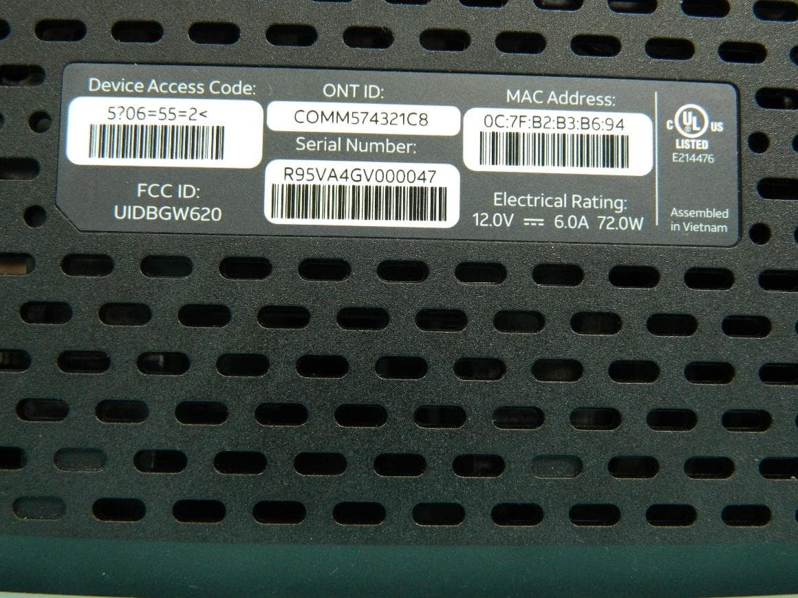
G95BGW620
Aug 26, 2024Wi-Fi 7 XGS-PON Gateway
Equipment Class
NII - Unlicensed National Information Infrastructure TX
G954981X2
Jan 10, 2024DOCSIS 3.1
Equipment Class
NII - Unlicensed National Information Infrastructure TXG95OWA7111
Jul 20, 2023Wi-Fi 6E Extender
Equipment Class
6PP - 15E 6 GHz Subordinate Indoor Device
G95EWM322T
Jul 17, 2023Wireless Access Point
Equipment Class
DTS - Digital Transmission System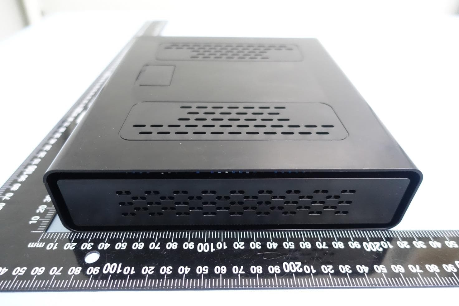
G95-CGA437T
Jan 14, 2023DOCSIS 3.1 Residential Voice Gateway
Equipment Class
NII - Unlicensed National Information Infrastructure TX