GCDAYXX0Reader
Rosslare Enterprises Ltd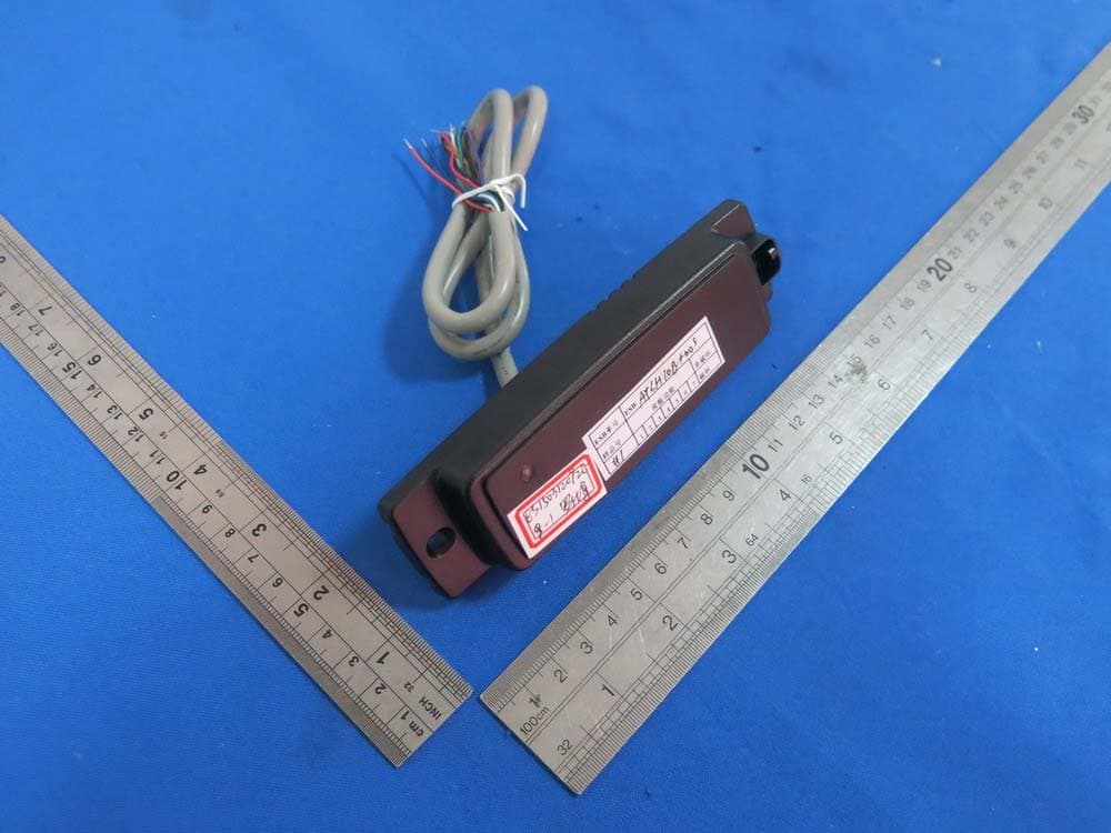
Click to zoom
Application Details
- Equipment Class
- DCD - Part 15 Low Power Transmitter Below 1705 kHz
- Date of Grant
- Sep 20, 2015
- Application Purpose
- Original Equipment
- Date of Application
- Sep 20, 2015
- Equipment Note
- Reader
- Frequency Range
- 0.12500000 - 0.12500000
- Company
- Rosslare Enterprises Ltd
- Country
- Hong Kong
Documents & Files
Document Text
Text extracted from the exhibit documents filed with the FCC. Open a document above to read the original.
Users Manual
AY-x20 Family Multi-format Proximity Readers Installation Manual 1 1. Introduction The AY-x20 is a family of RFID proximity card readers to be installed for use with access control systems. The AY-x20 family reads the proximity card and transmits its data to the access control system, using common multi-format Wiegand outputs. 1.1 Key Features Selectable Wiegand 26-Bit, Clock & Data Reads 26-Bit EM or Rosslare format cards Waterproof Green LED control line Red LED control line Buzzer control line Hold control line Optical tamper sensor Tamper output line UV-protected polycarbonate housing Figure 1: AY-x20 Family 2. Technical Specifications 2.1 Electrical Characteristics Specification AY-M20 AY-J20 AY-H20 AY-L20 AY-K20 AY-Q20 Power Supply Type Linear type (recommended) Operating Voltage Range* 5–16 VDC Absolute Maximum (non- operating) 18 VDC Current @ 12V Standby: 85 mA Maximum: 100 mA Read Range** 10 cm (3.9 in.) 8 cm (3.2 in.) 4 cm (1.6 in.) LED Control Input Dry Contact, N.O. Tamper Output Open collector, active low, max. sink current 16 mA Maximum Cable Distance to Controller 150 m (500 ft) RF Modulation ASK, 125 KHz Bit Rate 106 KHz * All input voltages should be limited to 1 A maximum. For VAC, the voltage range is peak-to-peak. ** Measured using a Rosslare proximity card or equivalent. Range also depends on electrical environment and proximity to metal. 2.2 7BEnvironmental Characteristics Specification AY-M20 AY-J20 AY-H20 AY-L20 AY-K20 AY-Q20 Operating Temp. Range -31°C to 63°C (-25°F to 145°F) Operating Humidity Range 0 to 95% (non-condensing) 2.3 8BPhysical Characteristics Model Dimensions (H x W x D) Weight AY-M20 88.9 x 88.9 x 15 mm (3.5 x 3.5 x 0.6 in.) 109 g (3.9 oz.) AY-J20 120.0 x 42.0 x 14 mm (4.7 x 1.7 x 0.6 in.) 88.5 g (3.1 oz.) AY-H20 109.9 x 74.9 x 15 mm (4.3 x 3.0 x 0.6 in.) 100 g (3.5 oz) AY-L20 144.9 x 42.9 x 20 mm (5.7 x 1.7 x 0.8 in.) 116 g (4.1 oz) AY-K20 79.9 x 39.9 x 12.8 mm (3. 2 x 1.6 x 0.5 in.) 70.5 g (2.5 oz) AY-Q20 120 x 76 x 20 mm (4.7 x 3.0 x 0.8 in.) 480 g (17.0 oz) AY-M20 AY-H20 AY-L20 AY-J20 AY-K20 AY-Q20 2 3. Installation 3.1 Installation Kit The installation kit consists of the following items to be used during the installation procedure: One mounting template Two pan head screws and wall plugs One L-shaped security screw tool One security screw 3.2 Mounting the AY-x20 Reader Before mounting, you should determine the best location for the reader. To mount the reader: 1. Peel off the back of the self-adhesive mounting label template and place it at the required mounting location. 2. Using the template as a guide, drill two holes (sizes indicated on the template) used for mounting the reader onto the surface. 3. Insert a suitable wall plug into each hole. 4. Drill a 10-mm (7/16”) hole for the cable. If mounting on metal, place a grommet or electrical tape around the edge of the hole. 5. Wire the reader to the controller as described in Section 4. A linear type power supply is recommended. 6. Remove the reader's snap-off front cover to reveal the two screw holes (see Figure 2 ). Figure 2: Removing the Top Cover 7. Align the two holes of the reader with those drilled in the wall and firmly attach the reader to the wall with two screws, whose size is indicated on the template. 8. Relocate the front cover onto the reader. The reader can also be mounted using strong epoxy glue. After application, the reader should be firmly held in place until the glue dries. Card readers are to be used with control panels whose power supply is UL Listed Class 2 or equivalent. 4. Wiring The AY-x20 is supplied with a 10-conductor 18” pigtail. To connect the reader to the controller: 1. Prepare the reader cable by cutting its jacket back about 3 cm (1¼") and strip the insulation from the wires about 1.2 cm (½"). 2. Prepare the controller cable by cutting its jacket back 3 cm (1¼") and strip the insulation from the wires about 1.2 cm (½"). 3. Splice the reader’s pigtail wires to the corresponding controller wires (as indicated in Table 1) and cover each joint with insulating tape. 4. If the tamper output is being utilized, connect the purple wire to the correct input on the controller. 5. Trim and cover all unused conductors. • The individual wires from the reader are color-coded according the Wiegand standard. • When using a separate power supply for the reader, this supply and that of the controller must have a common ground. • The reader’s cable shield wire should be preferably attached to an earth ground, or a signal ground connection at the panel, or power supply end of the cable. This configuration is best for shielding the reader cable from external interference. Table 1: Wiring Wire Color Wiegand 26-Bit Output Mode Clock & Data Output Mode Red +DC +DC Black Ground Ground Green Data 0 Data White Data 1 Clock Orange Green LED Green LED Brown Red LED Red LED Yellow Buzzer Buzzer Blue Hold Hold Purple Tamper Tamper Grey Open Input Connected to GND 3 5. Operation Instructions 5.1 Testing Once the reader is wired to a power supply and to the controller, you should test the reader. To test the reader: 1. Power up the reader. The LED and beeper activate one time. This indicates that the reader is working properly. 2. Present the appropriate type of proximity card to the reader. The LED momentarily flashes green and a short beep is emitted indicating that the card was read properly by the reader. After the card data is processed by the controller, the controller can then turn the LED green. Refer to the controller description of the LED operation if the reader LED is controlled by the controller. 5.2 Output Selection For Wiegand 26-bit operation, the grey wire should be held not connected. For Clock & Data operation, the grey wire should be connected to the ground 5.3 LED Control If the LED control wires (orange and brown) are not used (open), the reader LED remains red continuously, and flashes green momentarily when successfully reading a ca…
Text truncated - open the document above for the full version.
Cover Letter(s)
Rosslare Enterprises Limited Office of Engineering Technology Federal Communications Commission 7435 Oakland Mills Road Columbia, MD 21046 Date: 2015-09-15 Subject; Request for Confidentiality FCC ID: GCDAYXX0 To Whom It May Concern, Pursuant to the provisions of Sections 0.457 and 0.459 of Commission's rules (47CFR0.457, 0.459), we are requesting the Commission to withhold the following attachment(s) as confidential document from public disclosure indefinitely. • Schematic Diagram • Block Diagram • Part List • Operational Description • Tune-up Procedure Above mentioned document contains detailed system and equipment description are considered as proprietary information in operation of the equipment. The public disclosure of above documents might be harmful to our company and would give competitor an unfair advantage in the market. In additional to above mentioned documents, pursuant to Public Notice DA 04-1705 of the Commission' s policy, in order to comply with the marketing regulations in 47 CFT §2.803 and the importation rules in 47 CFR §2.1204, while ensuring that business sensitive information remains confidential until the actual marketing of newly authorized devices. We are requesting the commission to grant shot-term confidentiality request on the following attachment(s) for 180 days after the grant as outlined in Public Notice DA 04-1705. • External Photos • Internal Photos • Test Setup Photos • User Manual It is our understanding that all measurement test reports, FCC ID label format and correspondent during certification review process cannot be granted as confidential documents and those information will be available for public review once the grant of equipment authorization is issued. Sincerely, Signature: Name: Joe LeKostaj Title: Engineering Manager
Cover Letter(s)
Rosslare Enterprises Limited Letter of Authorization Company: Rosslare Enterprises Limited Address: Flat 12,9/F., Wing Fat lnd. Bldg.,12 Wang Tai Road , Kowloon Bay, Kowloon, Hong Kong Product Name: Reader Model Number: AY-K20, AY-L20, AY-H20, AY-M20, AY-J20 FCC Identifier: GCDAYXX0 We authorize MiCOM Labs Inc, 575 Boulder Court, Pleasanton, California 94566, USA, to act on our behalf on all matters concerning the above named equipment. Any individual within MiCOM Labs is authorized to act on our behalf and take action on the application. We declare that MiCOM Labs Inc, 575 Boulder Court, Pleasanton, California 94566, USA, is allowed to forward all information related to the approval project to the Federal Communication Commission and to discuss any issues concerning the approval application. Any and all acts carried out by MiCOM Labs on our behalf shall have the same effect as acts of our own. Name: Joe LeKostaj Date: 2015-09-15 Title: Engineering Manager Signature of applicant:
External Photos
General Appearance of the EUT
ID Label/Location Info
Label Location on EUT
Test Report
TRF No. FCC 15.209/A Page 1 of 21 Report No.: ES150312086E Ver.1.0 ELECTROMAGNETIC EMISSIONS COMPLIANCE REPORT INTENTIONAL RADIATOR CERTIFICATION TO FCC PART 15 SUBPART C REQUIREMENT OF Reader Model No.: AY-K20, AY-L20, AY-H20, AY-M20, AY-J20 FCC ID: GCDAYXX0 Trademark: Rosslare Report No.:ES150312086E Issue Date: September 17, 2015 Prepared for Rosslare Enterprises Limited Flat 12,9/F., Wing Fat lnd. Bldg.,12 Wang Tai Road , Kowloon Bay, Kowloon, Hong Kong Prepared by SHENZHEN EMTEK CO., LTD. Bldg 69, Majialong Industry Zone, Nanshan District, Shenzhen, Guangdong, China TEL: 86-755-26954280 FAX: 86-755-26954282 TRF No. FCC 15.209/A Page 2 of 21 Report No.: ES150312086E Ver.1.0 VERIFICATION OF COMPLIANCE Applicant: Rosslare Enterprises Limited Flat 12,9/F., Wing Fat lnd. Bldg.,12 Wang Tai Road , Kowloon Bay, Kowloon, Hong Kong Manufacturer: Rosslare Enterprises Limited Flat 12,9/F., Wing Fat lnd. Bldg.,12 Wang Tai Road , Kowloon Bay, Kowloon, Hong Kong Product Description: Reader Model Number: AY-K20, AY-L20, AY-H20, AY-M20, AY-J20 (Note: The samples are the same except appearance and model number. So AY-K20 was selected for full test.) Trademark: Rosslare We hereby certify that: The above equipment was tested by SHENZHEN EMTEK CO., LTD. The test data, data evaluation, test procedures, and equipment configurations shown in this report were made in accordance with the procedures given in ANSI C63.4 (2014) and the energy emitted by the sample EUT tested as described in this report is in compliance with conducted and radiated emission limits of FCC Rules Part 15.209(2014). The test results of this report relate only to the tested sample identified in this report. Date of Test : March 12, 2015 to April 11, 2015 Prepared by : Joe Xia/Editor Reviewer : Jack Li/Supervisor Approved & Authorized Signer : Lisa Wang/Manager TRF No. FCC 15.209/A Page 3 of 21 Report No.: ES150312086E Ver.1.0 Modified Information Version Summary Revision Date Report No. Ver.1.0 Original Report / ES150312086E TRF No. FCC 15.209/A Page 4 of 21 Report No.: ES150312086E Ver.1.0 Table of Contents 1 GENERAL INFORMATION .......................................................................................................................... 5 1.1 PRODUCT DESCRIPTION ............................................................................................................................ 5 1.2 TEST SYSTEM UNCERTAINTY ............................................................................................................ 6 1.3 TEST FACILITY .......................................................................................................................................... 6 2. SYSTEM TEST CONFIGURATION ............................................................................................................. 7 2.1 EUT CONFIGURATION ............................................................................................................................... 7 2.2 EUT EXERCISE ......................................................................................................................................... 7 2.3 TEST PROCEDURE .................................................................................................................................... 7 2.4 CONFIGURATION OF TESTED SYSTEM ........................................................................................................ 8 2 SUMMARY OF TEST RESULTS .................................................................................................................. 9 3 RADIATED EMISSION TEST ..................................................................................................................... 10 3.1 MEASUREMENT PROCEDURE ................................................................................................................... 10 3.2 TEST SET-UP (BLOCK DIAGRAM OF CONFIGURATION) ............................................................................. 10 3.3 MEASUREMENT EQUIPMENT USED ........................................................................................................... 11 3.4 RADIATED EMISSION LIMIT ....................................................................................................................... 11 3.5 MEASUREMENT RESULT .......................................................................................................................... 13 3.6 RADIATED MEASUREMENT PHOTOS: ........................................................................................................ 14 4 ANTENNA REQUIREMENT ....................................................................................................................... 15 4.1 RESULT .................................................................................................................................................. 15 APPENDIX (Photos of EUT) (5 pages) TRF No. FCC 15.209/A Page 5 of 21 Report No.: ES150312086E Ver.1.0 1 General Information 1.1 Product Description Characteristics Description Product Name Reader Model number AY-K20 Power Supply DC 5-16V Modulation ASK Operating Frequency Range 125KHz Number of Channels 1 channel Antenna Type Internal antenna Note: for a more detailed features description, please refer to the manufacturer’s specifications or the User's Manual. TRF No. FCC 15.209/A Page 6 of 21 Report No.: ES150312086E Ver.1.0 1.2 TEST SYSTEM UNCERTAINTY The following measurement uncertainty levels have been estimated for tests performed on the apparatus: Parameter Uncertainty Radio Frequency ±1x10^-5 Maximum Peak Output Power Test ±1.0dB Conducted Emissions Test ±2.0dB Radiated Emission Test ±2.0dB Power Density ±2.0dB Occupied Bandwidth Test ±1.0dB Band Edge Test ±3dB All emission, radiated ±3dB Antenna Port Emission ±3dB Temperature ±0.5°C Humidity ±3% Measurement Uncertainty for a level of Confidence of 95% 1.3 Test Facility Site Description EMC Lab. : Accredited by FCC, June 18, 2014 Th…
Text truncated - open the document above for the full version.
Test Setup Photos
Radiated Emission Setup Photos
Contact Information
Applicant
Ilan Ozer(Director)
Technical Contact
Shenzhen EMTEK Co., LtdLisa Wang
[email protected](86)75526954280
Bldg 69, Majialong Industry Zone · Shenzhen, Guangdong · China
Test Firm
EMTEK (Shenzhen) Co., Ltd.David Lee
Technical Specifications
| # | Rule Parts | Frequency Range | Power Output |
|---|---|---|---|
| 1 | 15C | 0.125 MHz - 0.125 MHz | - |
Other Applications from Rosslare Enterprises Ltd

GCD-AYK35
Aug 01, 2021Multi-Smart Readers
Equipment Class
DTS - Digital Transmission System
GCD-HLX24TH
Jan 27, 2016Advanced Wireless Security Panels
Equipment Class
DSC - Part 15 Security/Remote Control Transmitter
GCD-HLX24TG
Jan 27, 2016Advanced Wireless Security Panels
Equipment Class
DSC - Part 15 Security/Remote Control Transmitter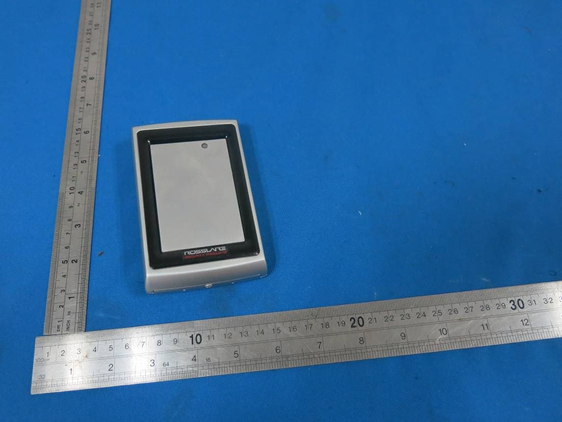
GCDAYQX0
Sep 20, 2015Reader
Equipment Class
DCD - Part 15 Low Power Transmitter Below 1705 kHz
GCD-HLX24G
Apr 28, 2015Wireless Security Panel
Equipment Class
DSR - Part 15 Remote Control/Security Device Transceiver