GKM-XT4820GPS Asset Tracking Device
Xirgo Technologies LLC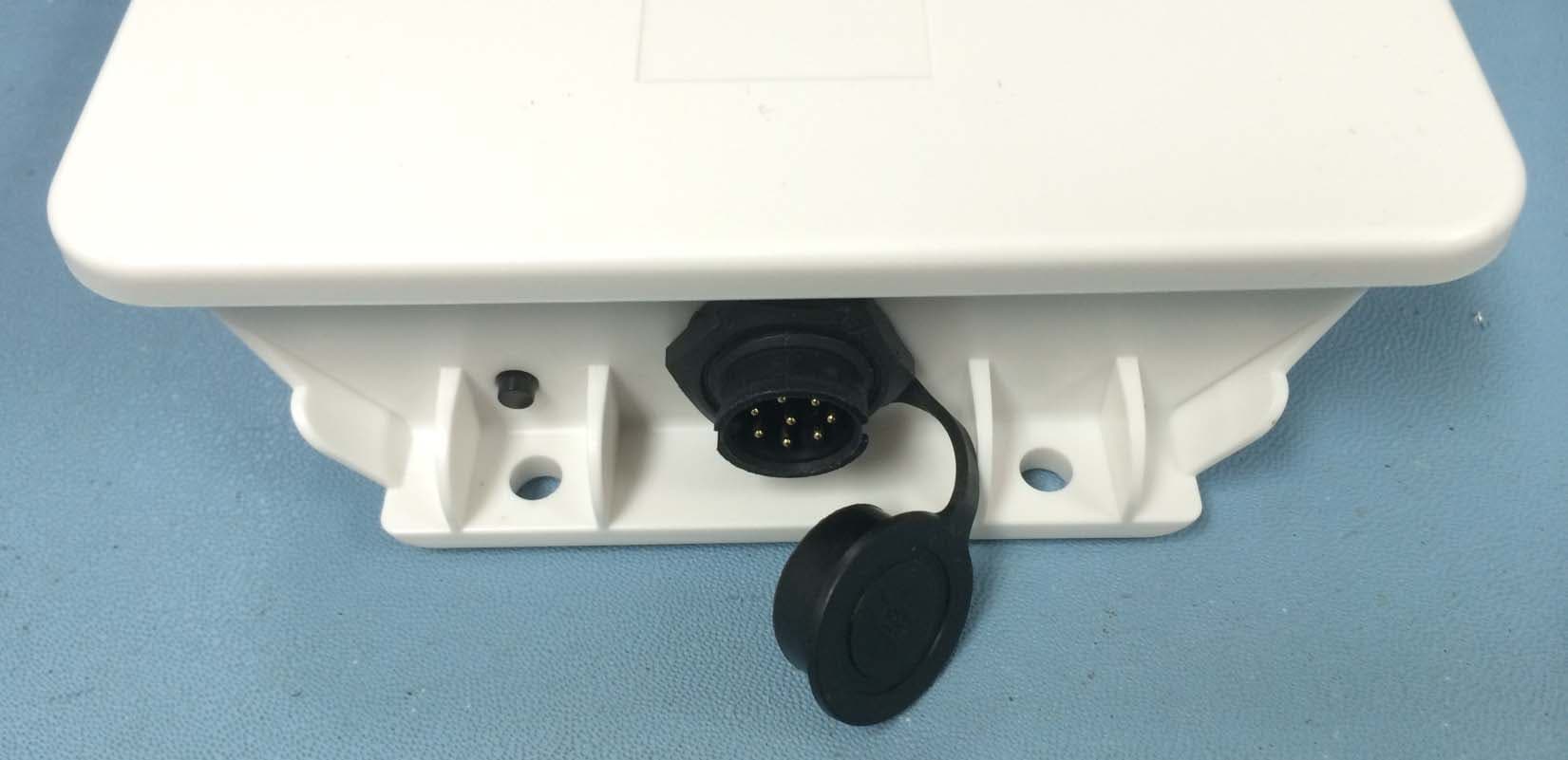
Click to zoom
Application Details
- Equipment Class
- DTS - Digital Transmission System
- Date of Grant
- Oct 15, 2014
- Application Purpose
- Original Equipment
- Date of Application
- Oct 15, 2014
- Equipment Note
- GPS Asset Tracking Device
- Frequency Range
- 2405.00000000 - 2475.00000000
- Company
- Xirgo Technologies LLC
- Country
- United States
Documents & Files
Document Text
Text extracted from the exhibit documents filed with the FCC. Open a document above to read the original.
Users Manual
1 XT-4860G2 User Guide Model: XT-4860G2 FCC ID: GKM-XT4820 IC ID: IC: 10281A-XT4820 Version 1.0 2 3 Table of Contents Document Change History .......................................................................................... 4 1 Introduction ............................................................................................................ 5 1.1 Feature Matrix ................................................................................................................................................................................. 5 2 Hardware Description .............................................................................................. 6 2.1 Hardware Specifications ............................................................................................................................................................. 7 2.2 Cable Harness Description ......................................................................................................................................................... 8 2.3 LED Description .............................................................................................................................................................................. 8 3 Device Mounting Options ........................................................................................ 9 3.1 Screw Mounting .............................................................................................................................................................................. 9 3.2 Magnetic Mounting ........................................................................................................................................................................ 9 3.3 Optional Cradle Mounting ........................................................................................................................................................ 10 4 Quick Start Guide ................................................................................................... 11 4.1 Device Wakeup ............................................................................................................................................................................. 11 4.2 Configuring the Device via SMS .............................................................................................................................................. 12 4 Document Change History Revision Date Author Changes 1.0 10/02/2014 N Barakat Document Initial Release 5 1 Introduction XT-4860G2 is an energy harvesting global multi-band 3G Dual Band platform supporting long term, remote deployments without the need to replace the self-charging battery. This installation guide describes the physical hardware, associated parts, the different mounting options available, and a quick start-up procedure. 1.1 Feature Matrix Feature Description Base Unit Zigbee® Upgrade 3G Communication Module with 2G fallback GPS Receiver for Tracking Applications Supports SMS, TCP, UDP, FTP Over-the-air Configuration and FW Upgrade Location Polling Periodic Reporting Wired or Virtual Ignition On/Off Reporting Direction Change Alerts Speed Threshold Alerts Mileage Threshold Alerts Main Battery Disconnect Alerts Heartbeat and Power-up/Reset Alerts Ignition Idle Alert (wired ignition only) Towing Start/Stop Alerts(wired ignition only) Movement Start/Stop Alerts (wired ignition only) 2 Digital Inputs Park Time Alerts (wired ignition only) Virtual Odometer Motion Sleep/Wake Configuration Settings Geofence (Radial, Rectangular, and Polygonal) Device Diagnostics (Battery voltage, connectivity, etc.) Wireless Sensor Connectivity Inter-device Communication 6 2 Hardware Description Below is a depiction of key interfaces of the XT-4860G2: The Associated Cable Harness that interfaces with the unit is shown below: Solar Panel LED Indicators Device Label Wake-up/ Zigbee Pairing Button Zigb 7-Pin Bayonet Connector 7 2.1 Hardware Specifications Technology 3G UMTS/HSDPA/HSUPA Model XT-4860G2 Frequency Band Dual-band Support Band II – 1900 MHz Band V – 850 MHz GPS Specification Receiver 50 channels 50 channels Receiver tracking Sensitivity -161 dBm Accuracy +/- 2.5m CEP (50% , -130 dBm, > 6 Satellites) Cold Start <33 sec Hot Start < 1 sec Power Requirements D.C. Power 8-24V, 12 V nominal Battery Internal 6600mAh rechargeable Li-Ion Physical Connection Interface Connector 8-pin attached harness Cellular/GPS Antenna Internal SIM Access Internal Programming Serial (UART Logic Level) Mechanical Case Material ABS plastic with weather-proofing for outdoor use Dimension 7.6” X 4.9” X 1.4” Weight < 18 oz. (Estimated) Operating Temperature -30°C to +70°C Certifications Product PTCRB ATT IC IP67 Carrier AT&T 8 2.2 Cable Harness Description Pin # Wire Color Pin Name Functional Description Port Characteristic 1 White IN1 Ignition Sense 8v to 24v, Internally pulled low 2 Yellow IN2 Input port 2.4 to 24V, < 0.2 V Note: Internally pulled high 3 Black Ground Ground 4 Green Out Output Port (Defaulted open circuit) 5 Blue UART-Rx External battery negative terminal 3.3V Logic Interface Com Port Settings: Baud rate: 115200 bps; Flow control: None; 8N1 6 Brown UART-Tx 3.3V Logic Interface Com Port Settings: Baud rate: 115200 bps; Flow control: None;8N1 7 Red VBATT Main battery voltage, DC 8-24 V 8 Orange ADC Analog Input 8-24 V 2.3 LED Description LED Description Status Cellular (Blue) Searching for Cellular Network LED OFF Cellular Carrier Lock Fast Blinking once every 1 second GPS (Green) Searching for satellite Solid GPS Lock Blinking Zigbee (Aurburn) TBD TBD 9 3 Device Mounting Options 3.1 Screw Mounting The XT-4860G2 has two flanges (two holes per) at each end of the housing for screw mounting the device to the mounting surface. 3.2 Magnetic Mounting The XT-4860G2 can also be eq…
Text truncated - open the document above for the full version.
External Photos
Xirgo Technologies XT‐4860G2 FCC ID: GKM‐XT4820 IC: IC: 10281A‐XT4820
ID Label/Location Info
XT-4860G2 Label Specification FCC: GKM-XT4820 IC ID: 10281A-XT4820 Size: 1.5”x1.0” Face Sensor
Internal Photos
Xirgo Technologies XT‐4860G2 FCC ID: GKM‐XT4820 IC: IC: 10281A‐XT4820
Test Report
CETECOM Inc. 6370 Nancy Ridge Drive, Suite 101-102 San Diego, CA 92121 U.S.A. Phone: + 1 (858) 362 2400 Fax: + 1 (858) 587 4809 E-mail: [email protected] http://www.cetecom.com CETECOM Inc. is a Delaware Corporation with Corporation number: 2905571 V1.0 2013-04-24 © Copyright by CETECOM FCC/IC Test Report FOR Xirgo Technologies Model Number: XT-4860G5 Product Description: GPS Asset Tracking Device FCC ID: GKM-XT4800 IC ID: 10281A-XT4800 47 CFR Part 15.247 for DTS Systems IC RSS-210 Issue 8 TEST REPORT #: EMC_XIRGO-080-14001_DTS_rev2 DATE: 08-27-2017 Test Report #: EMC_Xirgo-080-14001_DTS_rev2 FCC ID: GKM-XT4800 Date of Report : 08-27-2014 IC ID: 10281A-XT4800 Page 2 of 48 TABLE OF CONTENTS 1 Assessment ......................................................................................................................................... 4 2 Administrative Data .......................................................................................................................... 5 2.1 Identification of the Testing Laboratory Issuing the Test Report ............................................................. 5 2.2 Identification of the Client ........................................................................................................................ 5 2.3 Identification of the Manufacturer ............................................................................................................ 5 3 Equipment under Test (EUT) .......................................................................................................... 6 3.1 Specification of the Equipment under Test ............................................................................................... 6 3.2 Identification of the Equipment Under Test (EUT) .................................................................................. 7 3.3 Identification of Accessory Equipment ..................................................................................................... 7 3.4 Environmental conditions during Test: ..................................................................................................... 7 3.5 Dates of Testing: ....................................................................................................................................... 7 3.6 Other Testing Notes: ................................................................................................................................. 7 4 Subject of Investigation .................................................................................................................... 8 5 Summary of Measurement Results .................................................................................................. 9 6 Measurements .................................................................................................................................. 10 6.1 Radiated Measurement Procedure ...........................................................................................................10 6.2 Measurement Method: ............................................................................................................................10 6.3 Radiated Measurement Procedure ...........................................................................................................10 6.4 Sample Calculations for Radiated Measurements ...................................................................................12 6.5 Conducted Measurement Procedure .......................................................................................................13 6.6 Maximum Peak Conducted Output Power .............................................................................................14 6.6.1 Limits: .................................................................................................................................................14 6.6.2 Test Conditions: .................................................................................................................................14 6.6.3 Test Procedure: ..................................................................................................................................14 6.6.4 Test Results: ........................................................................................................................................15 6.6.5 Test Data/Plots: ..................................................................................................................................16 6.7 Emission and Occupied Bandwidth ........................................................................................................18 6.7.1 Limits: .................................................................................................................................................18 6.7.2 Test Conditions: .................................................................................................................................18 6.7.3 Test Procedure: ..................................................................................................................................18 6.7.4 Test Results: ........................................................................................................................................18 6.7.5 Test Data/plots: ..................................................................................................................................19 6.8 Maximum Power Spectral Density Level in the Fundamental Emission ................................................22 6.8.1 Limits: .................................................................................................................................................22 6.8.2 Test procedure: ...................................................................................................................................22 6.8.3 Test Conditions: ..............................................................…
Text truncated - open the document above for the full version.
Test Setup Photos
Test Report #: EMC_XIRGO-080-14001_DTS_rev2 FCC ID: GKM-XT4800 Date of Report : 08-27-2014 IC ID: 10281A-XT4800 Page 1 of 6 Model Number: XT-4860G5 Product Description: GPS Asset Tracking Device Manufacturer: Xirgo Technologies, Inc FCC ID: GKM-XT4800 IC ID: 10281A-XT4800 Test Site Information: CETECOM Inc. Miltpitas, CA USA CETECOM Inc. San Diego, CA USA Test Report #: EMC_XIRGO-080-14001_DTS_rev2 FCC ID: GKM-XT4800 Date of Report : 08-27-2014 IC ID: 10281A-XT4800 Page 2 of 6 1 Conducted Setup Test Report #: EMC_XIRGO-080-14001_DTS_rev2 FCC ID: GKM-XT4800 Date of Report : 08-27-2014 IC ID: 10281A-XT4800 Page 3 of 6 2 Radiated Emissions <30 MHz: Test Report #: EMC_XIRGO-080-14001_DTS_rev2 FCC ID: GKM-XT4800 Date of Report : 08-27-2014 IC ID: 10281A-XT4800 Page 4 of 6 3 Radiated Emissions 30 MHz to 1GHz Test Report #: EMC_XIRGO-080-14001_DTS_rev2 FCC ID: GKM-XT4800 Date of Report : 08-27-2014 IC ID: 10281A-XT4800 Page 5 of 6 4 Radited Emissions 1GHz to 18GHz Test Report #: EMC_XIRGO-080-14001_DTS_rev2 FCC ID: GKM-XT4800 Date of Report : 08-27-2014 IC ID: 10281A-XT4800 Page 6 of 6 5 Radiated Emissions >18 GHz
Contact Information
Applicant
Edward Gabrelian(Engineering Manager)
Test Firm
CETECOM Inc.Meinolf Glunz
[email protected]408-586-6301
Technical Specifications
| # | Rule Parts | Frequency Range | Power Output |
|---|---|---|---|
| 1 | 15C | 2.40 GHz - 2.48 GHz | 11.00 mW |
Other Applications from Xirgo Technologies LLC
GKM-XVA-OBDPRO
May 15, 2026XVA-CBL-OBDRO-01
Equipment Class
JAB - Part 15 Class B Digital DeviceGKM-XFV-100
May 08, 2026Asset Tracker
Equipment Class
DTS - Digital Transmission SystemGKM-XVD-302
Apr 30, 2026Video Telematcis
Equipment Class
JAB - Part 15 Class B Digital DeviceGKM-XAB-200
Apr 30, 2026Asset Tracker
Equipment Class
DTS - Digital Transmission System
GKM-XT1040S6
Sep 28, 2023Wireless Door Sensor
Equipment Class
DTS - Digital Transmission System