GKM-XT6000REEFER CONTAINER MONITORING DEVICES
Xirgo Technologies LLC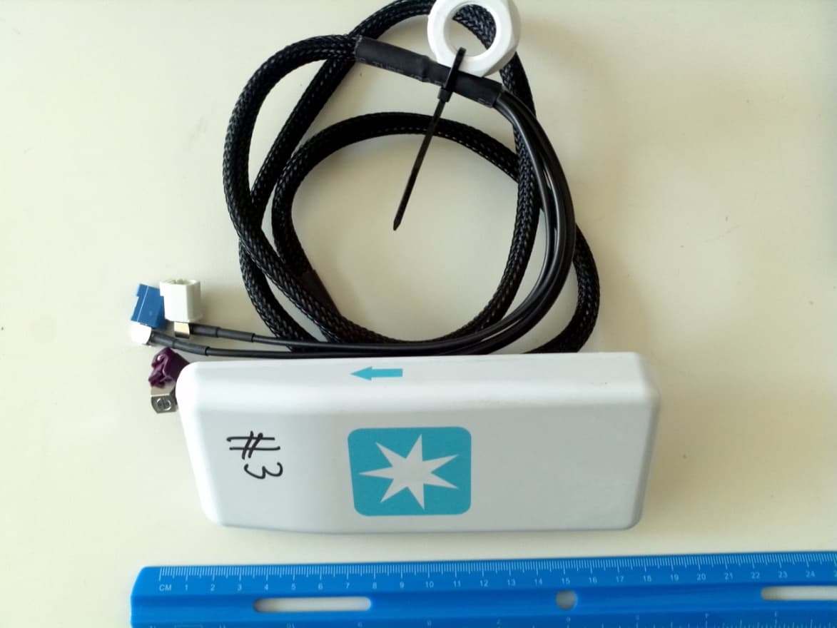
Click to zoom
Application Details
- Equipment Class
- DTS - Digital Transmission System
- Date of Grant
- May 30, 2012
- Application Purpose
- Original Equipment
- Date of Application
- May 30, 2012
- Equipment Note
- REEFER CONTAINER MONITORING DEVICES
- Frequency Range
- 2405.00000000 - 2475.00000000
- Company
- Xirgo Technologies LLC
- Country
- United States
Documents & Files
Document Text
Text extracted from the exhibit documents filed with the FCC. Open a document above to read the original.
Users Manual
XT-6000 User Guide Terminology a) Unit – Xirgo XT-6000 b) Asset – Customer product that the XT-6000 is mounted to. 1. XT-6000 Installation: a) Install unit bracket b) Secure unused high voltage communication connector into unit bracket c) Install unit into bracket Push unit into bracket Secure 2 torx screws Push On/Off Switch d) Connect antenna wires to unit e) Connect 3 and 7 pin connectors to unit f) Bundle the wires by using cable ties and fix to unit g) Connect unit ribbon harness to controller XT-6000 User Guide h) Attach TK bracket to unit i) Fit unit with bracket to TK controller and tighten upper screws j) Connect antenna wires to unit k) Connect Power Cable Harness X1 RED wire to Transformer X1 tap, and X2 BLACK wire (with ground terminal) to Controller Chassis. l) Connect 7 pin from unit ribbon harness to unit m) Connect 3 pin harness to unit n) Bundle the wires by using cable ties and fix to unit XT-6000 User Guide Test: o) Connect power plug to power source p) Put unit into install mode (on/off button) – see section below q) Observe installer LED for green pass – see section below r) If installer LED fail, refer to trouble shooting guide and fix issue s) Take unit out of installer mode t) Close the controller door. u) Installation is complete. LED Operation 1. GPS LED (Green): OFF – GPS OFF Blinking – GPS Lock (position obtained) ON solid – No GPS Lock 2. Asset LED (Red, disabled during install mode): OFF – Asset OFF Slow blink – Asset communications OK Med blink – Physical connect on 7 pin but no asset communications Fast blink – No physical connect on 7 pin ON solid – software upload in progress 3. CELL LED (Blue): OFF – Scanning for network or cell module is off Blinking – Registered on cellular network ON solid – Periods of network data transmission active 4. WLAN LED (Orange, disabled during install mode): OFF - Mesh OFF Slow blink – Mesh Bound Fast blink - Mesh searching for network ON solid - No battery detected 5. “INSTALL” LED To use the “INSTALL” LED, use the following steps: a. Enter Install mode i. Make sure unit is powered on by applying asset AC or by pressing the unit ON/OFF button (the unit is on when the GPS LED is flashing or on solid green). ii. Press and hold ON/OFF button until “INSTALL” LED is blinking blue then release iii. Wait for unit to reboot, indicated by fast blinking green LED b. Observe “INSTALL” LED i. Testing in progress is indicated by fast blinking green LED (approx. 1-6 min) ii. Testing is complete when solid LED is observed: Solid GREEN: All test conditions PASS Solid BLUE: No AC & No asset Communications but all others PASS Solid RED: Any other conditions (fails) XT-6000 User Guide c. Exiting install mode i. Press and hold ON/OFF button for approx. 5 seconds any time after solid LED indication from step 2 above ii. Or wait for timeout of install mode which is 15 minutes from start of solid LED status Important notes about the “INSTALL” LED and install mode: 1. “INSTALL” LED is only operational when the unit is put into the ‘install mode’. It does not provide information during normal operation. 2. The “INSTALL” LED and the install mode do not work during off power reporting periods (periodic, listen, motion start/motion stop). 3. Install mode will disable normal unit communications with the asset and the server and the following conditions will exist: a. No SMS processing. b. No processing of forward commands from the server to the unit. c. No LED status function on the “WLAN” or “ASSET” LEDs during install mode. 4. During the install mode testing, the unit will check for the following: a. AC power is on b. Unit is communicating with asset c. Unit has communicated with server d. Physical connection detected on the 7 pin connector e. Battery is detected f. GPS position obtained g. 2G/3G cellular registration and activation is good General Notes LED Blink Rates: Slow Blink – once per three second period Med Blink – once per second Fast Blink – three times per second ON/OFF Push Button: U OFF and not on AC power o press ON/OFF Push Button to wake unit (1 sec then release) o unit will wake for 15 minutes before shutting down (no AC) Unit ON and not on AC power or Install Mode o press and hold for > 15 seconds to initialize unit ship mode shut down XT-6000 User Guide Regulatory Statements: FCC: This device complies with Part 15 of the FCC Rules. Operation is subject to the following two conditions: (1) this device may not cause harmful interference, and (2) this device must accept any interference received, including interference that may cause undesired operation. Changes or modifications made to this equipment not expressly approved by Xirgo Technology may void the FCC authorization to operate this equipment. Radiofrequency radiation exposure Information: This equipment complies with FCC radiation exposure limits set forth for an uncontrolled environment. This equipment should be installed and operated with minimum distance of 20 cm between the radiator and your body. This transmitter must not be co-located or operating in conjunction with any other antenna or transmitter. IC: This device complies with Industry Canada licence-exempt RSS standard(s). Operation is subject to the following two conditions: (1) this device may not cause interference, and (2) this device must accept any interference, including interference that may cause undesired operation of the device. Le présent appareil est conforme aux CNR d'Industrie Canada applicables aux appareils radio exempts de licence. L'exploitation est autorisée aux deux conditions suivantes : (1) l'appareil ne doit pas produire de brouillage, et (2) l'utilisateur de l'appareil doit accepter tout brouillage radioélectrique subi, même si le brouillage est susceptible d'en compromettre le onctionnement. Under Industry Canada regulations, this radio transmitter may only operate using an antenna of a type and maximum (or lesser) gain approved for the transm…
Text truncated - open the document above for the full version.
Cover Letter(s)
Federal Communication Commission Equipment Authorization Division, Application Processing Branch 7435 Oakland Mills Road Columbia, MD 21048 05/23/2012 Dear FCC Examiner, Pursuant to Paragraphs §0.457 and 0.459 of the Commission’s Rules (47 C.F.R.) and Section §552(b)(4) of the Freedom of Information Act, Xirgo Technologies, Inc., requests permanent confidentiality for the following exhibits FCC ID Number Product Title/Model GKM-XT6000 XT-6000 For the product stated above, we request that the following information be held confidential: 1) Block Diagram 2) Schematics 3) Operational Description The above exhibits contain Xirgo Technologies, Inc.’s trade secrets and proprietary information that could be of benefit to our competitors regarding the design of our device. This material is not customarily available to the general public and we request that it be withheld from public inspection. If you have any questions, please feel free to contact me at the address shown below. Sincerely, Shawn Aleman Vice President of Business Development
External Photos
External Photos: Model: XT‐6000 FCC ID: GKM‐XT6000 IC ID: 10281A‐XT6000 Fig.1: Top View Fig.2: Bottom View Fig. 3: Back View Fig.4 Front View Fig. 5 Side View 1 Fig. 6. Side View 2 Fig. 7. Antenna
ID Label/Location Info
Label ID and Location info: Model: XT‐6000 FCC ID: GKM‐XT6000 IC ID: 10281A‐XT6000 Label Location.
Internal Photos
Internal Photos: Model: XT‐6000 FCC ID: GKM‐XT6000 IC ID: 10281A‐XT6000 Fig.1: Internal View (with cover open) Fig.2: Internal View (Bottom) Fig. 3: Internal View (Top)
RF Exposure Info
RF Exposure Evaluation Report FOR: Model Name: Xirgo 6000 Reefer container monitoring devices FCC ID: GKM-XT6000 IC ID: 10281A-XT6000 References: 1. FCC OET Bulletin 65 Supplement 2. FCC CFR Part 1 (1.1307 &1.1310), Part 2 (2.1091) 3. RSS-102- Radio Frequency Exposure Compliance of Radiocommunication Apparatus Issue 4 March 2010 Test Report #: EMC_ XIRGO_038_12001_MPE FCC ID: GKM-XT6000 Date of Report : 2012-05-09 IC ID: 10281A-XT6000 Feb 2012. Rev 1.0 Page 2 of 10 1 Administrative Data 1.1 Identification of the Testing Laboratory Issuing the Test Report Company Name: CETECOM Inc. Department: Compliance Address: 411 Dixon Landing Road Milpitas, CA 95035 U.S.A. Telephone: +1 (408) 586 6200 Fax: +1 (408) 586 6299 Test Lab Director: Heiko Strehlow Responsible Project Leader: Calvin Lee 1.2 Identification of the Client Applicant’s Name: Xirgo Technologies Street Address: 188 Camino Ruiz City/Zip Code Camarillo, CA 93012 Country USA Contact Person: Shawn Aleman Phone No. 805-426-5243 e-mail: [email protected] 1.3 Identification of the Manufacturer Manufacturer’s Name: Same as above Manufacturers Address: City/Zip Code Country Test Report #: EMC_ XIRGO_038_12001_MPE FCC ID: GKM-XT6000 Date of Report : 2012-05-09 IC ID: 10281A-XT6000 Feb 2012. Rev 1.0 Page 3 of 10 2 Equipment under Test (EUT) 2.1 Specification of the Equipment under Test Model No: XT-6000 Hardware Revision : XT6000-001; Software Revision : XT6000-01; Integrated Module Information: uBlox LISA-U200 HW Ver: 146A00 SW Ver: 21.21 FCC-ID: GKM-XT6000 IC-ID: 10281A-XT6000 Frequency: GSM 850: 824.2-848.8MHz; PCS 1900: 1850.2- 1909.8MHz FDD V: 826.4-846.6MHz; FDD II: 1852.4-1907.6MHz GPS RX 1.575 GHz ZigBee: 2405-2475 MHz Type(s) of Modulation: GSM/UMTS: GMSK; 8-PSK; QPSK; 16QAM Zigbee: OQPSK Number of channels: GSM850: 125 and PCS 1900: 300 FDD II: 278/ FDD V: 103 Zigbee: 15 Antenna Type: Hirschmann HCEL-S2-0125A-01 Tri-Band Antenna: GPS, Cellular and WLAN Antenna Gain @ 2.4 GHz band = 5dBi (As reported by the manufacturer) Co-located Transmitters/ Antennas? Yes No Rated Power supply: 20V – 48V AC (or) 30V DC Rated Operating temperature range: -40°C ~ 70°C Prototype / Production unit: Prototype Device Category: Fixed Installation Mobile Portable Exposure Category: Occupational/ Controlled General Population/ Uncontrolled Test Report #: EMC_ XIRGO_038_12001_MPE FCC ID: GKM-XT6000 Date of Report : 2012-05-09 IC ID: 10281A-XT6000 Feb 2012. Rev 1.0 Page 4 of 10 3 Assessment This report serves as the Technical Information regarding RF Exposure evaluation of the below identified device according to the rules as stipulated in the documents listed under References above. The device meets the RF exposure limits, or - for some of it's radio functions / bands - the conditions for exemption from routine evaluation as defined in the referenced FCC and IC rule parts. Company Description Model # Xirgo Technologies Reefer container monitoring devices XT-6000 2012-05-17 Compliance Calvin Lee (EMC Engineer) Date Section Name Signature Test Report #: EMC_ XIRGO_038_12001_MPE FCC ID: GKM-XT6000 Date of Report : 2012-05-09 IC ID: 10281A-XT6000 Feb 2012. Rev 1.0 Page 5 of 10 4 RF Exposure Evaluation Requirements 4.1 FCC: Calculations can be made to predict RF field strength and power density levels around typical RF sources using the general equations (3) and (4) on page 19 of the following FCC document: “OET Bulletin 65, Edition 97-01 - Evaluating Compliance with FCC Guidelines for Human Exposure to Radio frequency Electromagnetic Fields”. The table below is excerpted from Table 1B of 47 CFR 1.1310 titled Limits for Maximum Permissible Exposure (MPE), Limits for General Population/Uncontrolled Exposure: Frequency Range (MHz) Power density (mW/cm 2 ) Averaging time (minutes) 300 – 1500 f (MHz) /1500 30 1500 – 100.000 1.0 30 Using the equation from page 19 of OET Bulletin 65, Edition 97-01: 2 4R PG S where: S = power density (in appropriate units, e.g. mW/cm 2 ) P = power input to the antenna (in appropriate units, e.g., mW) G = power gain of the antenna in the direction of interest relative to an isotropic radiator R = distance to the center of radiation of the antenna (appropriate units, e.g., cm) Note: 1. This device is to be used only for fixed and mobile applications. 2. The antenna(s) used for this transmitter must be installed to provide a separation distance of at least 20 cm from all the persons and must not be co-located or operating in conjunction with any other antenna or transmitter. Additionally, according to § 2.1091: The limit for <1.5 GHz mobile operations where no routine evaluation is required is: 1.5W ERP The limit for >1.5 GHz mobile operations where no routine evaluation is required is: 3W ERP 4.2 IC: RSS-102 Section 2.5.2 RF exposure evaluation is required if the separation distance between the user and the device's radiating element is greater than 20 cm, except when the device operates as follows: below 1.5 GHz and the maximum EIRP of the device is equal to or less than 2.5 W; at or above 1.5 GHz and the maximum EIRP of the device is equal to or less than 5 W. RSS-102 4.2: RF Field strength limits for devices used by the General Public (Uncontrolled Environment): Power density 300MHz- 1500 MHz= f/150 W/m 2 1500 MHz- 1500000 MHz= 10 W/m 2 Test Report #: EMC_ XIRGO_038_12001_MPE FCC ID: GKM-XT6000 Date of Report : 2012-05-09 IC ID: 10281A-XT6000 Feb 2012. Rev 1.0 Page 6 of 10 5 Measurement procedure: 5.1 Radiated power measurement- ERP/EIRP- 1. Connect the equipment as shown in the above diagram with the EUT’s antenna in center of the turn table. 2. Adjust the settings of the Digital Radio Communication Tester (DRT) to set the EUT to its maximum power at the required channel. 3. Set the spectrum analyzer to the channel frequency. Set the analyzer to measure peak hold with the required settings. 4. Rotate the EUT 360. Record the peak level in dBm (LVL). 5. Replace the EUT with a vertically polarized half wave di…
Text truncated - open the document above for the full version.
Test Setup Photos
Project #: XIRGO-038-12001; Model: XT-6000 FCC ID: GKM-XT6000 Date: 2012-05-15 IC ID: 10281A-XT6000 Page 1 of 4 Measurement Setup Photos: ERP/EIRP Measurements: Fig. 1 EUT Setup Fig. 2 ERP/EIRP Test Setup Project #: XIRGO-038-12001; Model: XT-6000 FCC ID: GKM-XT6000 Date: 2012-05-15 IC ID: 10281A-XT6000 Page 2 of 4 Fig. 3 Radiated Emissions: 30M- 1GHz Fig. 4 Radiated Emissions 1-18GHz Project #: XIRGO-038-12001; Model: XT-6000 FCC ID: GKM-XT6000 Date: 2012-05-15 IC ID: 10281A-XT6000 Page 3 of 4 Fig. 5 Field Strength Measurements <30 MHz Fig. 6 Field Strength Measurements <1GHz Project #: XIRGO-038-12001; Model: XT-6000 FCC ID: GKM-XT6000 Date: 2012-05-15 IC ID: 10281A-XT6000 Page 4 of 4 Fig.7 Radiated Emissions >18GHz
Contact Information
Applicant
Edward Gabrelian(Engineering Manager)
Test Firm
CETECOM Inc.Meinolf Glunz
[email protected]408-586-6301
Technical Specifications
| # | Rule Parts | Frequency Range | Power Output |
|---|---|---|---|
| 1 | 15C | 2.40 GHz - 2.48 GHz | 14.00 mW |
Other Applications from Xirgo Technologies LLC
GKM-XVA-OBDPRO
May 15, 2026XVA-CBL-OBDRO-01
Equipment Class
JAB - Part 15 Class B Digital DeviceGKM-XFV-100
May 08, 2026Asset Tracker
Equipment Class
DTS - Digital Transmission SystemGKM-XVD-302
Apr 30, 2026Video Telematcis
Equipment Class
JAB - Part 15 Class B Digital DeviceGKM-XAB-200
Apr 30, 2026Asset Tracker
Equipment Class
DTS - Digital Transmission System
GKM-XT1040S6
Sep 28, 2023Wireless Door Sensor
Equipment Class
DTS - Digital Transmission System