GPI-M5N001MedSense Base
General Sensing Limited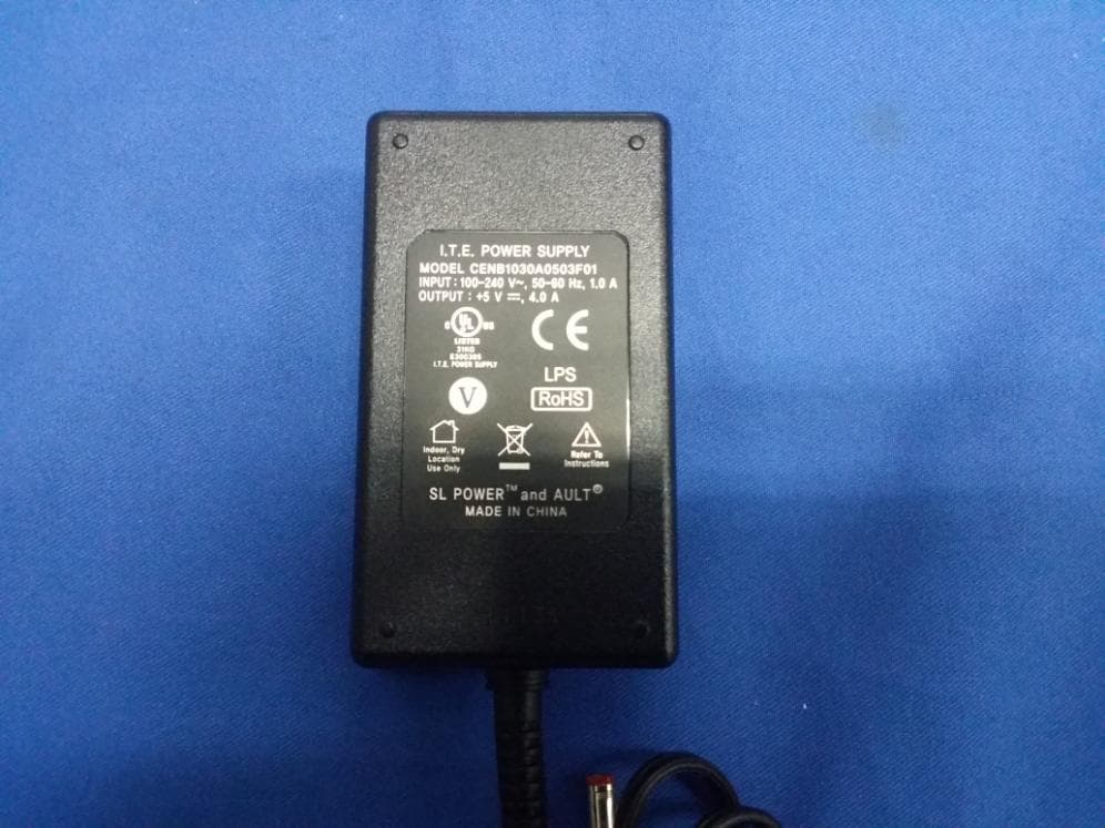
Click to zoom
Application Details
- Equipment Class
- DXX - Part 15 Low Power Communication Device Transmitter
- Date of Grant
- Aug 06, 2014
- Application Purpose
- Original Equipment
- Date of Application
- Aug 06, 2014
- Equipment Note
- MedSense Base
- Frequency Range
- 2402.00000000 - 2480.98000000
- Company
- General Sensing Limited
- Country
- Hong Kong
Documents & Files
Document Text
Text extracted from the exhibit documents filed with the FCC. Open a document above to read the original.
Users Manual
MedSense ™ ® Base M5N001 3 How MedSense Works 4 Setting Up the MedSense Base 6 Using Up the MedSense Base 6 Legal Statements 8 Contents Welcome to MedSense Dear MedSense user, We would like to thank you for using our product and welcome you to the MedSense community. We share your goal of achieving the highest possible level of hygiene in your hospital, and we hope using our product makes your life simpler. Sincerely, The General Sensing Team 45 How MedSense Works MedSense is a combination of four easy-to-use wireless devices that monitor and record compliance performance at point-of-care areas. These devices take advantage of low-power wireless communication and the latest web technologies to offer you a simple, powerful, and accurate hand hygiene compliance monitoring solution. 1.2.3. 4. 1. The MedSense Badge The MedSense Badge, worn like an identity card, collects hand hygiene compliance data as the healthcare worker delivers care around the hospital. 2. The MedSense Beacon The MedSense Beacon is a low-profile, battery-powered device that is placed above a patient bed or other point of care with a semi- permanent adhesive backing. The Beacon establishes a wireless patient zone that allows the Badge to identify hand hygiene opportunities. 3. The MedSense Dispenser Monitor The MedSense Dispenser Monitor acts as a holster for sanitizer bottles. When a healthcare worker uses a sanitizer bottle, the Dispenser Monitor signals the user’s Badge, which in turn records a hand hygiene action. 4. The MedSense Base The MedSense Base functions as a wireless base station through which Badges upload compliance data to MedSense HQ. The Base also functions as a battery charger for the Badge, capable of charging up to sixteen Badge batteries to full capacity in two hours. The MedSense HQ MedSense HQ, General Sensing’s cloud-based web application, is what ties all four devices together. 67 Setting Up the MedSense Base • Locate the Base centrally, such as on a nursing station. Keep the Base away from metal structures, as this may cause connection problems. • The Base can be mounted on either a tabletop or on the wall, using the screws provided. • Connect the Base to the Ethernet port using the Ethernet cable provided. • The Base is connected once the light turns green. MedSense Base Router Internet Ethernet Cable Using the MedSense Base CHARGING BATTERIES The Base can charge up to sixteen Badge batteries to full capacity in two hours. Individual indicator lights on each battery slot indicate charging status. A pulsing blue light means a battery is charging, with a solid blue light indicating a fully charged battery. BASE CONNECTION STATUS Refer to the status LED connected next to the Ethernet port on the side of the Base. 1. 2. Insert battery into base. 4. BLINKING RED Remove battery from badge. BLUE Solid blue light indicates a fully charged battery.Insert charged battery into badge. 3. Base Online .......................................................................................Green, Solid Base Attempting to Connect .......................................................Amber, Solid User Attention Required ..........................................................Green, Blinking Base Station Internal Error .....................................................Amber, Blinking TROUBLESHOOTING LED State: Solid Amber Status: Base Station Attempting to Connect Explanation: Your Base is trying to connect to MedSense HQ. The Base will go through this step during normal operation, but it should transition to Online (solid green) after about 8 seconds. If the solid amber state persists, then there is a problem. 89 Steps to correct: 1. Check to make sure that the router is properly connected to the network. You can do this by checking the status lights on your router or by trying to bring up a web page on a computer connected to the network through the same router. 2. If your router IS NOT properly connected to the Internet, contact the MedSense support team. 3. If your router IS properly connected to the Internet, make sure that your Base is connected as specified in the typical network diagram on p. 7. If you are still experiencing this error after executing the troubleshooting steps above, contact the MedSense support team. LED State: Blinking Green* Status: User Attention Required Explanation: Ethernet cable is plugged in, but Base cannot get an IP address. Steps to correct: 1. Check that router is functioning normally. If your router is functioning normally, reset the Base by disconnecting the power source for 10 seconds and then reconnecting. 2. The Base may need advanced Ethernet configuration to run on your network. Contact the MedSense support team to configure your Base. If you are still experiencing this error after executing the troubleshooting steps above, contact the MedSense support team. LED State: Blinking Amber* Status: Internal error Explanation: An internal error has occurred. Step to correct: 1. Reset your Base by disconnecting the power source. Wait 5 seconds, and then reconnect the power source. If you are still experiencing this error after executing the troubleshooting steps above, contact the MedSense support team. *Your Base will attempt to restart itself after 10 seconds in this state. CARE INSTRUCTIONS Wipe down in place with a damp cloth. POWER The Base should only be used with the included power supply. Please contact the MedSense support team for further information. 1110 Legal Statements FCC Statement This equipment has been tested and found to comply with the limits for a Class B digital device, pursuant to part 15 of the FCC rules. These limits are designed to provide reasonable protection against harmful interference in a residential installation. This equipment generates, uses, and can radiate radio frequency energy and, if not installed and used in accordance with the instructions, may cause harmful interference to radio communications. However, there is no guarantee tha…
Text truncated - open the document above for the full version.
Users Manual
MedSense ™ ® Base M5N001 3 How MedSense Works 4 Setting Up the MedSense Base 6 Using Up the MedSense Base 6 Legal Statements 8 Contents Welcome to MedSense Dear MedSense user, We would like to thank you for using our product and welcome you to the MedSense community. We share your goal of achieving the highest possible level of hygiene in your hospital, and we hope using our product makes your life simpler. Sincerely, The General Sensing Team 45 How MedSense Works MedSense is a combination of four easy-to-use wireless devices that monitor and record compliance performance at point-of-care areas. These devices take advantage of low-power wireless communication and the latest web technologies to offer you a simple, powerful, and accurate hand hygiene compliance monitoring solution. 1.2.3. 4. 1. The MedSense Badge The MedSense Badge, worn like an identity card, collects hand hygiene compliance data as the healthcare worker delivers care around the hospital. 2. The MedSense Beacon The MedSense Beacon is a low-profile, battery-powered device that is placed above a patient bed or other point of care with a semi- permanent adhesive backing. The Beacon establishes a wireless patient zone that allows the Badge to identify hand hygiene opportunities. 3. The MedSense Dispenser Monitor The MedSense Dispenser Monitor acts as a holster for sanitizer bottles. When a healthcare worker uses a sanitizer bottle, the Dispenser Monitor signals the user’s Badge, which in turn records a hand hygiene action. 4. The MedSense Base The MedSense Base functions as a wireless base station through which Badges upload compliance data to MedSense HQ. The Base also functions as a battery charger for the Badge, capable of charging up to sixteen Badge batteries to full capacity in two hours. The MedSense HQ MedSense HQ, General Sensing’s cloud-based web application, is what ties all four devices together. 67 Setting Up the MedSense Base • Locate the Base centrally, such as on a nursing station. Keep the Base away from metal structures, as this may cause connection problems. • The Base can be mounted on either a tabletop or on the wall, using the screws provided. • Connect the Base to the Ethernet port using the Ethernet cable provided. • The Base is connected once the light turns green. MedSense Base Router Internet Ethernet Cable Using the MedSense Base CHARGING BATTERIES The Base can charge up to sixteen Badge batteries to full capacity in two hours. Individual indicator lights on each battery slot indicate charging status. A pulsing blue light means a battery is charging, with a solid blue light indicating a fully charged battery. BASE CONNECTION STATUS Refer to the status LED connected next to the Ethernet port on the side of the Base. 1. 2. Insert battery into base. 4. BLINKING RED Remove battery from badge. BLUE Solid blue light indicates a fully charged battery.Insert charged battery into badge. 3. Base Online .......................................................................................Green, Solid Base Attempting to Connect .......................................................Amber, Solid User Attention Required ..........................................................Green, Blinking Base Station Internal Error .....................................................Amber, Blinking TROUBLESHOOTING LED State: Solid Amber Status: Base Station Attempting to Connect Explanation: Your Base is trying to connect to MedSense HQ. The Base will go through this step during normal operation, but it should transition to Online (solid green) after about 8 seconds. If the solid amber state persists, then there is a problem. 89 Steps to correct: 1. Check to make sure that the router is properly connected to the network. You can do this by checking the status lights on your router or by trying to bring up a web page on a computer connected to the network through the same router. 2. If your router IS NOT properly connected to the Internet, contact the MedSense support team. 3. If your router IS properly connected to the Internet, make sure that your Base is connected as specified in the typical network diagram on p. 7. If you are still experiencing this error after executing the troubleshooting steps above, contact the MedSense support team. LED State: Blinking Green* Status: User Attention Required Explanation: Ethernet cable is plugged in, but Base cannot get an IP address. Steps to correct: 1. Check that router is functioning normally. If your router is functioning normally, reset the Base by disconnecting the power source for 10 seconds and then reconnecting. 2. The Base may need advanced Ethernet configuration to run on your network. Contact the MedSense support team to configure your Base. If you are still experiencing this error after executing the troubleshooting steps above, contact the MedSense support team. LED State: Blinking Amber* Status: Internal error Explanation: An internal error has occurred. Step to correct: 1. Reset your Base by disconnecting the power source. Wait 5 seconds, and then reconnect the power source. If you are still experiencing this error after executing the troubleshooting steps above, contact the MedSense support team. *Your Base will attempt to restart itself after 10 seconds in this state. CARE INSTRUCTIONS Wipe down in place with a damp cloth. POWER The Base should only be used with the included power supply. Please contact the MedSense support team for further information. 1110 Legal Statements FCC Statement This equipment has been tested and found to comply with the limits for a Class B digital device, pursuant to part 15 of the FCC rules. These limits are designed to provide reasonable protection against harmful interference in a residential installation. This equipment generates, uses, and can radiate radio frequency energy and, if not installed and used in accordance with the instructions, may cause harmful interference to radio communications. However, there is no guarantee tha…
Text truncated - open the document above for the full version.
Block Diagram
PWM LED Drive Signal RF DAUGHTER CARD Status LED ARM7 CC2500 2.4GHz Radio (see Chipcon datasheet excerpts) 16-Slot Charging PCB Multiple Status LEDs Power Source Select / Protection 3V Linear Regulator Digital Analog Power RF Source DC Jack Ethernet Port + Protection SPI Interface 26 MHz Crystal 18.432 MHz Crystal External Flash Memory USB Jack USB Interface Ethernet Controller 25 MHz Crystal Network Interface Wire Whip Antenna
Cover Letter(s)
06/26/2014 BABT TCB Balfour House, Churchfield Road, Walton-on-Thames, Surrey, KT12 2TD Dear Sir or Madam, We, General Sensing Limited Unit 716, Cyberport 1, 100 Cyberport Road, Pok Fu Lam, Hong Kong hereby authorize TÜV SÜD Certification and Testing (China) Co., Ltd. Shenzhen Branch Building 12&13, Zhiheng Wisdomland Business Park, Nantou Checkpoint Road 2, Nanshan District, Shenzhen City, 518052, P.R. China Felix Li Phone: +86-755-88286998-3243 e-mail: felix [email protected] to act as our agent in all matters relating to applications for equipment authorization, including the signing of all documents relating to these matters. We also hereby certify that neither we nor any party to this application are subject to denial of U.S Federal benefits, which include FCC benefits, pursuant to section 5301 of Anti-Drug Abuse Act of 1988, U.S.C 862 because of conviction for possession or distribution of controlled substance. This authorization is application to product: Type of equipment: MedSense Base Model name: M5N001 FCC ID: GPI-M5N001 This authorization expires one year from the current date. Sincerely, CTO: Jonathan Gips Telephone Number: +1 617 785 7882 E-mail: [email protected]
Cover Letter(s)
06/26/2014 BABT TCB Balfour House, Churchfield Road, Walton-on-Thames, Surrey, KT12 2TD Confidentiality Request FCC ID: GPI-M5N001 Pursuant to Sections 0.457(d)(1)(ii) and 0.459 of the Commission’s Rules, we General Sensing Limited hereby requests permanent confidential treatment of information accompanying this application as outlined below: Schematics Parts List PCB Layout Block Diagrams Operational Description The above materials contain trade secrets and proprietary information not customarily released to the public. The public disclosure of these matters might be harmful to the Applicant and provide unjustified benefits to its competitors. The Applicant understands that pursuant to Rule 0.457(d)(1)(ii), disclosure of this Application and all accompanying materials will not be made before the date of the Grant for this Application. Yours sincerely, CTO: Jonathan Gips Telephone Number: +1 617 785 7882 E-mail: [email protected]
External Photos
External photos
ID Label/Location Info
WARNING: Use only power adaptor listed in the user manual. This device complies with part 15 of the FCC Rules. Operation is subject to the following two conditions: (1) This device may not cause harmful interference, and (2) this device must accept any interference received, including interference that may cause undesired operation. FCCID: GPI-M5N001 IC: 7310A-M5N001 Manufactured in China CAN ICES-3 (B)/NMB-3(B) MedSenseModel:M5N001 www.generalsensing.com
ID Label/Location Info
Label Location Label location
Internal Photos
Internal Photos Antenna
RF Exposure Info
Jiangsu TÜV Product Service Ltd. – Shenzhen Branch 6 floor, H Hall, Century Craftwork Culture Square, No. 4001, Fuqiang Road, Futian District, Shenzhen 518048, P. R. China, Tel. +86 755 8828 6998, Fax: +86 755 8828 5299 Exemption from Routine Evaluation – SAR Evaluation for M5N001 1. Introduction M5N001 is a Medsense base, which is a 2.4GHz short range device. 2. Limit and Guidelines on Exposure to Electromagnetic Fields According to RSS-102 § (2.5.1), SAR evaluation is required if the separation distance between the user and the device is less than or equal to 20 cm, except when the device operates: above 2.2 GHz up to 3 GHz inclusively and its output power (i.e. the higher of the conducted or radiated (e.i.r.p.) source-based time-averaged output power) is less than, or equal to 20 mW for General Public Use and 100 mW for Controlled Use 3. Calculation method Maximum radiated power of M5N001 is 0.30mW(-5.24dBm), it is below 20mW, Exemption from Routine Evaluation Limits – RF Exposure Evaluation, so SAR evaluation is not necessary. TÜV SÜD Certification and Testing (China) Co., Ltd. Shenzhen Branch Reviewed by: Prepared By: Ken Li/ EMC Project Manager Felix Li/ EMC Project Engineer Date: 2014-03-09 Date: 2014-03-09
Test Report
Report Number: 68.760.12.308.01 Page 1 of 30 TÜV SÜD Certification and Testing (China) Co., Ltd. Shenzhen Branch 6 floor, H Hall, Culture Creative Park, No. 4001, Fuqiang Road, Futian District, Shenzhen 518048, P. R. China, FCC/IC - TEST REPORT Report Number : 68.760.12.308.01 Date of Issue: 04 March, 2014 Model : M5N001 Product Type : MedSense Base Applicant : General Sensing Limited Address : Unit 716, Cyberport 1, 100 Cyberport Road, Pok Fu Lam, Hong Kong Manufacture : General Sensing Limited Address : Unit 716, Cyberport 1, 100 Cyberport Road, Pok Fu Lam, Hong Kong Test Result : Positive Negative Total pages including Appendices : 30 TÜV SÜD Certification and Testing (China) Co., Ltd. Shenzhen Branch is a subcontractor to TÜV SÜD Product Service GmbH according to the principles outlined in ISO 17025. TÜV SÜD Certification and Testing (China) Co., Ltd. Shenzhen Branch reports apply only to the specific samples tested under stated test conditions. Construction of the actual test samples has been documented. It is the manufacturer's responsibility to assure that additional production units of this model are manufactured with identical electrical and mechanical components. The manufacturer/importer is responsible to the Competent Authorities in Europe for any modifications made to the production units which result in non-compliance to the relevant regulations. TÜV SÜD Certification and Testing (China) Co., Ltd. Shenzhen Branch shall have no liability for any deductions, inferences or generalizations drawn by the client or others from TÜV SÜD Certification and Testing (China) Co., Ltd. Shenzhen Branch issued reports. This report is the confidential property of the client. As a mutual protection to our clients, the public and ourselves, extracts from the test report shall not be reproduced except in full without our written approval Report Number: 68.760.12.308.01 Page 2 of 30 TÜV SÜD Certification and Testing (China) Co., Ltd. Shenzhen Branch 6 floor, H Hall, Culture Creative Park, No. 4001, Fuqiang Road, Futian District, Shenzhen 518048, P. R. China, 1 Table of Contents 1 Table of Contents.......................................................................................... 2 2 Details about the Test Laboratory..................................................................... 3 3 Description of the Equipment Under Test............................................................ 4 4 Summary of Test Standards............................................................................. 5 5 Summary of Test Results................................................................................ 6 6 General Remarks.......................................................................................... 7 7 Test setups 8 8 Technical Requirements................................................................................. 9 8.1 Conducted emission AC power port 9 8.2 Field strength of emissions and Restricted bands ....................................... 12 8.3 Out of band emissions .......................................................................... 21 8.4 20dB Bandwidth & 99% bandwidth .......................................................... 26 9 Test equipment list 29 10 System Measurement Uncertainty................................................................... 30 Report Number: 68.760.12.308.01 Page 3 of 30 TÜV SÜD Certification and Testing (China) Co., Ltd. Shenzhen Branch 6 floor, H Hall, Culture Creative Park, No. 4001, Fuqiang Road, Futian District, Shenzhen 518048, P. R. China, 2 Details about the Test Laboratory Details about the Test Laboratory Test site1: Company name: TÜV SÜD Certification and Testing (China) Co., Ltd. Shenzhen Branch 6th Floor, H Hall,Culture Creative Park, No. 4001, Fuqiang Road, Futian District 518048, Shenzhen,P.R.C. Telephone: 86 755 8828 6998 Fax: 86 755 8828 5299 Test site2: Company name: Audix Technology (shenzhen) Co.,Ltd Block Shenzhen, Science & Industry Park, Nantou, Shenzhen, Guangdong, China Telephone: 86 755 2663 9496 Fax: 86 755 2663 2877 Report Number: 68.760.12.308.01 Page 4 of 30 TÜV SÜD Certification and Testing (China) Co., Ltd. Shenzhen Branch 6 floor, H Hall, Culture Creative Park, No. 4001, Fuqiang Road, Futian District, Shenzhen 518048, P. R. China, 3 Description of the Equipment Under Test Description of the Equipment Under Test Product: MedSense Base Model no.: M5N001 Brand Name: MedSense Options and accessories: NIL Rating: Adaptor model: CENB1030A0503F01 input:100-240V~, 50-60Hz, 1.0A output: +5V, 4.0A RF Transmission Frequency: 2402MHz - 2480.980MHz Antenna Gain: 5dBi Description of the EUT: NIL Auxiliary Equipment Used during Test: DESCRIPTION MANUFACTURER MODEL NO.(SHIELD) S/N(LENGTH) --- --- --- --- Report Number: 68.760.12.308.01 Page 5 of 30 TÜV SÜD Certification and Testing (China) Co., Ltd. Shenzhen Branch 6 floor, H Hall, Culture Creative Park, No. 4001, Fuqiang Road, Futian District, Shenzhen 518048, P. R. China, 4 Summary of Test Standards Test Standards FCC Part 15 Subpart C 10-1-2013 Edition PART 15 - RADIO FREQUENCY DEVICES Subpart C - Intentional Radiators RSS-Gen Issue 3 December 2010 General Requirements and Information for the Certification of Radio Apparatus RSS-210 Issue 8 December 2010 RSS-210 — Licence-exempt Radio Apparatus (All Frequency Bands): Category I Equipment Report Number: 68.760.12.308.01 Page 6 of 30 TÜV SÜD Certification and Testing (China) Co., Ltd. Shenzhen Branch 6 floor, H Hall, Culture Creative Park, No. 4001, Fuqiang Road, Futian District, Shenzhen 518048, P. R. China, 5 Summary of Test Results Technical Requirements FCC Part 15 Subpart C, RSS-Gen, RSS-210 Test Condition Pages Test Site Test Result Pass Fail N/A 15.207 & RSS-Gen A7.2.4 Conducted emission AC power port* 9 Site 2 §15.205(a), §15.209(a), §15.249(a), §15.249(c) & RSS-210 A2.9(a), RSS-Gen 7.2.2 Field strength of emissions and Restricted bands 12 Site 2 RSS-GEN 4.10 Receiver Spurious Emissions* -- Site 2 §15.…
Text truncated - open the document above for the full version.
Test Setup Photos
Conducted emission Radiation emission (below 1G) Radiation emission (Above 1G)
Contact Information
Applicant
Jonathan Gips(Chief Technology Officer)
Test Firm
Audix Technology (Shenzhen) Co., Ltd.Smart Tsai
Technical Specifications
| # | Rule Parts | Frequency Range | Power Output |
|---|---|---|---|
| 1 | 15C | 2.40 GHz - 2.48 GHz | - |
Other Applications from General Sensing Limited
GPI-M5K001
Aug 06, 2014MedSense Badge
Equipment Class
DXX - Part 15 Low Power Communication Device Transmitter
GPI-M5M001
Dec 17, 2012Wireless Transmitter
Equipment Class
DXX - Part 15 Low Power Communication Device Transmitter
GPI-M5P001
Oct 24, 2012Wireless hand hygiene monitor
Equipment Class
DXX - Part 15 Low Power Communication Device Transmitter