GU67410Wireless Print Server Transmitter Module
Avery Dennison Retail Information Services, LLC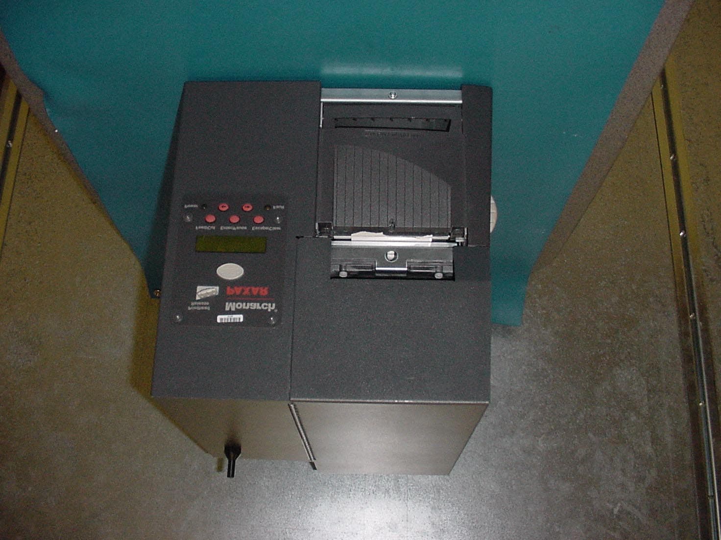
Click to zoom
Application Details
- Equipment Class
- DTS - Digital Transmission System
- Date of Grant
- Oct 14, 2002
- Application Purpose
- Original Equipment
- Date of Application
- Oct 14, 2002
- Equipment Note
- Wireless Print Server Transmitter Module
- Frequency Range
- 2412.00000000 - 2462.00000000
- Country
- United States
Documents & Files
Document Text
Text extracted from the exhibit documents filed with the FCC. Open a document above to read the original.
Users Manual
Rhein Tech Laboratories Report: Modular Approval 360 Herndon Parkway FCC: Part 15.247 Suite 1400 Industry Canada: RSS-210 FCC ID: GU67410 Herndon, VA 20170 http://www.rheintech.com Model: 7410 Wireless Print Server Page 65 of 98 APPENDIX J: MANUAL Please refer to the following pages. TC9850ENOI Rev. AC 9/02 DRAFT 2001 Paxar Corporation. All rights reserved. Paxar Monarch 7410 Print Server Each product and program carries a respective written warranty, the only warranty on which the customer can rely. Paxar reserves the right to make changes in the product, the programs, and their availability at any time and without notice. Although Paxar has made every effort to provide complete and accurate information in this manual, Paxar shall not be liable for any omissions or inaccuracies. Any update will be incorporated in a later edition of this manual. 2001 Paxar Corporation. All rights reserved. No part of this publication may be reproduced, transmitted, stored in a retrieval system, or translated into any language in any form by any means, without the prior written permission of Paxar Corporation. Trademarks MONARCH is a registered trademark of Monarch Marking Systems, Inc. 7410 and 9850 are trademarks of Monarch Marking Systems, Inc. Paxar is a trademark of Paxar Corporation. Paxar Corporation 170 Monarch Lane Miamisburg, OH 45342 Regulatory Compliance Paxar RF products are designed to be compliant with the rules and regulations in the locations into which they are sold and will be labeled as required. The majority of Paxar RF devices are type approved and do not require the user to obtain license or authorization before using the equipment. Any changes or modifications to Paxar equipment not expressly approved by Paxar could void the user authority to operate the equipment. FCC RF Exposure Guidelines To comply with FCC exposure requirements, antennas that are mounted externally at remote locations or operating near users at stand-alone desktop of similar configurations must operate with a minimum separation distance of 20 cm from all persons. Declaration of Conformity for RF Exposure: The radio module has been evaluated under FCC Bulletin OET 65C and found compliant to the requirements as set forth in CFR 47 Sections 2.1091, 2.1093, and 15.247 (b) (4) addressing RF Exposure from radio frequency devices. Radio Frequency Interference Requirements This device has been tested and found to comply with the limits for a Class A digital device pursuant to Part 15 of the Federal Communications Commissions Rules and Regulation. These limits are designed to provide reasonable protection against harmful interference when the equipment is operated in a commercial environment. This equipment generates, uses, and can radiate radio frequency energy and, if not installed and used in accordance with the instruction manual, may cause harmful interference to radio communications. Operation of this equipment in a residential area is likely to cause harmful interference in which case the user will be required to correct the interference at his own expense. However, there is no guarantee that interference will not occur in a particular installation. If the equipment does cause harmful interference to radio or television reception, which can be determined by turning the equipment off and on, the user is encouraged to try to correct the interference by one or more of the following measures: n Re-orient or relocate the receiving antenna. n Increase the separation between the equipment and receiver. n Connect the equipment into an outlet on a circuit different from that which the receiver is connected. n Consult the dealer or an experienced radio/TV technician. CAUTION: The Part 15 radio device operates on a non-interference basis with other devices operating at this frequency when using the listed antenna. Collocation Statement: This device must not be collocated with any other antenna or transmitters. 2 Radio Frequency Interference Requirements - Canada This device complies with RSS 210 of Industry & Science Canada. Operation is subject to the following two conditions: (1) this device may not cause harmful interference and (2) this device must accept any interference received, including interference that may cause undesired operation. This Class A digital apparatus meets the requirements of the Canadian Interference-Causing Equipment Regulations. Cet appareil numérique de la Classe A especte toutes les exigencies du Reglement sur le Materiél Brouilleur du Canada. European Economic Area The European variant is intended for use throughout the European Economic Area, however authorization for use restricted as follows: European standards dictate maximums radiated transmit power of 100 mW EIRP and frequency range 2.400 –2.4835 GHz. France, the equipment is to be restricted to the 2.4465 – 2.4835 GHz frequency range. Belgium outside, the equipment is to be restricted to the 2.460 – 2.4835 GHz frequency range. Operation in Italy requires a user license. i TABLE OF CONTENTS Installing the Print Server Hardware....................................................1-1 System Requirements........................................................................1-1 Network Protocols Supported.............................................................1-2 Checking the Print Server Hardware...................................................1-3 Sample Test Page..........................................................................1-6 Verifying Successful Installation.........................................................1-7 Configuring the 802.11b and IP Settings................................................2-1 Configuring the Print Server...............................................................2-1 Before You Begin..............................................................................2-1 Installing the Software.......................................................................2-2 Management Methods.....…
Text truncated - open the document above for the full version.
Cover Letter(s)
Rhein Tech Laboratories Report: Modular Approval 360 Herndon Parkway FCC: Part 15.247 Suite 1400 Industry Canada: RSS-210 FCC ID: GU67410 Herndon, VA 20170 http://www.rheintech.com Model: 7410 Wireless Print Server Page 56 of 98 APPENDIX C: AGENCY AUTHORIZATION LETTER Please refer to the following page.
Cover Letter(s)
Rhein Tech Laboratories Report: Modular Approval 360 Herndon Parkway FCC: Part 15.247 Suite 1400 Industry Canada: RSS-210 FCC ID: GU67410 Herndon, VA 20170 http://www.rheintech.com Model: 7410 Wireless Print Server Page 57 of 98 APPENDIX D: CONFIDENTIALITY REQUEST LETTER (IF APPLICABLE) Please refer to the following page.
Cover Letter(s)
October 15, 2002 American TCB, Inc. 6371 Whittier Avenue Suite C110 McLean, VA 22101 To Whom It May Concern: In the assembly of the Paxar® 7410 wireless print server for use in Paxar® Thermal Barcode Printers, we will use Loctite® 262 to permanently attach Part # 124558 Right Angle Antenna, or Part # 124559 Stub Antenna, to Part # 124560 Adapter Antenna Cable. This is in compliance with Federal Communications Commission Public Notice DA 00-1087 dated May 22, 2000, which clarifies antenna connector requirements for Part 15 Unlicensed Transmitters. In paragraph one, “A transmitter that utilizes a permanently attached antenna...”. In conjunction with this solution, Paxar will pursue implementation of a reverse-threaded antenna connection system for Part # 124558 and Part # 124559 to Part # 124560 Adapter Antenna Cable. Furthermore, Paxar will ensure that non-standard connections are adhered to between the RF output connector, antenna cable, and the antenna itself in accordance with the commission’s rules. This is in compliance with Federal Communications Commission Public Notice DA 00-1087 dated May 22, 2000, which clarifies antenna connector requirements for Part 15 Unlicensed Transmitters. In paragraph one, “...or a transmitter that uses a unique coupling at the antenna and at any cable connector between the transmitter and the antenna...”. The reverse-threaded antenna for metal covers will be the same antenna used in Part # 124559, the 2.4 GHz ISM Miniature Stud Mount Omni Directional Antenna MMSO2300. This is purchased with the 3” RG-188A/U flying lead and the antenna connector added. The reverse-threaded antenna for plastic covers will be a different part number from the same manufacturer with the same specifications. The antenna used in Part # 124558 is MHWS2400SMA, which has a male SMA connector on it. The reverse-threaded manufacturer part number is the MHWS2400SMART, which carries the same specifications as the MHWS2400SMA. Regards, James A. Bacher Senior Engineer, Paxar Corporation
Cover Letter(s)
Federal Communications Commission 7435 Oakland Mills Road Columbia, MD 21046 October 15, 2002 To Whom It May Concern: The Paxar model 7410 wireless print server can be used inside a printer with a plastic housing with a right-angle antenna, or a printer with a metal housing with a stub antenna. It is our intention to continue to use the model 7410 wireless print server in printers with either a plastic or metal housing, with their respective antennas. Paxar requires that the wireless print server be granted as a wireless print server with limited modular approval. The print server meets the intent of the commission’s Part 15 Unlicensed Modular Transmitter Approval document DA 00-1407: 1) The RF section of the print server, i.e. PCMCIA WLAN card has its own shielding. 2) The modulation/data input is buffered, ie. PCMCIA WLAN card. 3) The PCMCIA WLAN card has its own voltage regulator. 4) The connector between the RF output and the antenna uses a unique loctite style connector. 5) The print server was not tested as a standalone device, but rather an integral part of the wireless print server, as the card on its own cannot interface with the printer. The PCMCIA Card must be inserted into the wireless print server, which in turn is connected to the printer's main PCB. It is the intention of the manufacturer to use this print server in similar printers with metal housing and the stub antenna, or plastic housing with the right-angle antenna. The print server would only be used in the aforementioned configurations that justify the limited modular approval. 6) An exterior label referring to the enclosed module will be placed on the printer. A sample has been submitted. 7) All specific operating requirements of the print server can be found in the user manual. 8) The print server complies with the commission’s RF MPE exposure requirements. Please refer to the test report. Sincerely, James A. Bacher, Senior Engineer CC: Jeanne Duckett Senior Electrical Engineer Hugh Dayton Paxar Corporation 170 Monarch Lane Miamisburg, Ohio 453452 1-937-865-2020 1-937-865-2048 [email protected]
Cover Letter(s)
American Telecommunications Certification Body Inc. 6731 Whittier Ave, McLean, VA 22101 October 14, 2002 RE: Monarch Marketing Systems, Inc, dba Paxar Corporation FCC ID: GU67410 After a review of the submitted information, I have a few comments on the above referenced Application. 1) The sample label shows the labeling placed on the Ethernet interface board. However, there is a concern that a different PCMCIA card could get inserted into the device which would mean that the label would no longer be valid. Therefore, the labeling should be placed on the transmitter portion of the device itself (PCMCIA Card). Please note that the FCC ID placed on the PCMCIA card is no longer considered valid because of the change in antennas from its original submittal. Also, please note that from our research the PCMCIA card used is only approved for an integrated internal antenna, not external antennas as used. 2) It is recommended that the label placed on the exterior of the device contain reference to the internal module and the FCC ID on a single line. Please refer to the attached file Section 6. 3) Please provide a cover letter addressing the modular requirements as given in the attached file provided. This letter should also address the limited modular aspect of the application as we discussed, and the applicability of testing it in the configuration it was versus testing it as a standalone. 4) It is recommended that this application cover the PCMCIA Card only as a limited module approval. 5) Please provide an updated antenna connector attestation that references the modular PCMCIA card (instead of the printer model numbers). Also, since there are 3 possible connector points (at the module, at the antenna, and the flying lead between the two), please adjust the attestation letter to clearly refer to using non-standard connections between all connections between the module and the antenna. 6) Please explain how the device was tested in 3 orthogonal planes as stated in 2.1 of the test report. 7) Since the backplane of both models tested appears to be metal, please provide more descriptive information (drawings, etc.) regarding the metal and plastic housings referenced in the test report. 8) Please adjust the information in Table 2-2 (FCC ID's, etc) as we discussed today. 9) Please explain what test distance was used for the measurements made in table 5.3. 10) Please explain which antenna is expected to be used with which enclosure. 11) FYI, From our discussion today, the limited modular approval will be for the PCMCIA card for use in printservers manufactured by Monarch Marking systems only and must use a metal or plastic case as specified in the application. 12) FYI, The conducted emissions limits are not consistent. The plastic housing was showing Class B limits, while the metal housing was showing Class A limits. However, both sets of measurements meet with the 15.207 requirements. 13) FYI, I believe the Canadian document number on the label should be ICES-003, not ICES-0003. Timothy R. Johnson Examining Engineer Direct Phone: 404-414-8071 mailto: [email protected] The items indicated above must be submitted before processing can continue on the above referenced application. Failure to provide the requested information may result in application termination. Correspondence should be considered part of the permanent submission and may be viewed from the Internet after a Grant of Equipment Authorization is issued. Please do not respond to this correspondence using the email reply button. In order for your response to be processed expeditiously, you must submit your documents through the AmericanTCB.com website. Also, please note that partial responses increase processing time and should not be submitted. Any questions about the content of this correspondence should be directed to the sender.
Cover Letter(s)
American Telecommunications Certification Body Inc. 6731 Whittier Ave, McLean, VA 22101 October 14, 2002 RE: Monarch Marketing Systems, Inc, dba Paxar Corporation FCC ID: GU67410 After a review of the submitted information, I have a few comments on the above referenced Application. 1) The sample label shows the labeling placed on the Ethernet interface board. However, there is a concern that a different PCMCIA card could get inserted into the device which would mean that the label would no longer be valid. Therefore, the labeling should be placed on the transmitter portion of the device itself (PCMCIA Card). Please note that the FCC ID placed on the PCMCIA card is no longer considered valid because of the change in antennas from its original submittal. Also, please note that from our research the PCMCIA card used is only approved for an integrated internal antenna, not external antennas as used. Response : Please refer to the revised label exhibit, uploaded with this response, that reflects the label placement on the front of the PCMCIA card. 2) It is recommended that the label placed on the exterior of the device contain reference to the internal module and the FCC ID on a single line. Please refer to the attached file Section 6. Response : Please refer to the revised label exhibit uploaded with this response. 3) Please provide a cover letter addressing the modular requirements as given in the attached file provided. This letter should also address the limited modular aspect of the application as we discussed, and the applicability of testing it in the configuration it was versus testing it as a standalone. Response : Please refer to the modular approval letter uploaded with this response. 4) It is recommended that this application cover the PCMCIA Card only as a limited module approval. Response : Please refer to the letter referenced in #3. The manufacturer requests a limited modular approval on the wireless print server model 7410. 5) Please provide an updated antenna connector attestation that references the modular PCMCIA card (instead of the printer model numbers). Also, since there are 3 possible connector points (at the module, at the antenna, and the flying lead between the two), please adjust the attestation letter to clearly refer to using non-standard connections between all connections between the module and the antenna. Response : Please refer to the revised client attestation letter uploaded with this response. 6) Please explain how the device was tested in 3 orthogonal planes as stated in 2.1 of the test report. Response : The right-angle antenna used on the plastic housing is designed with a 360 degree swivel. This allows the antenna to be positioned in the XY, YZ and ZX planes. The stub antenna used on the metal housing is fix-mounted, so it was necessary to physically position this antenna with respect to the orthogonal planes. 7) Since the backplane of both models tested appears to be metal, please provide more descriptive information (drawings, etc.) regarding the metal and plastic housings referenced in the test report. Response : The backplane on both models is an integral part of the main metal chassis. The chassis is used in both models with plastic housing and metal housing. All printer circuit boards and other control modules are directly secured to the main metal chassis. 8) Please adjust the information in Table 2-2 (FCC ID's, etc) as we discussed today. Response : Please refer to the revised test report uploaded with this response. 9) Please explain what test distance was used for the measurements made in table 5.3. Response : The test distance was three meters. 10) Please explain which antenna is expected to be used with which enclosure. Response : The stub antenna is used only with the metal housing, and the right-angle antenna is used only with the plastic housing. 11) FYI, From our discussion today, the limited modular approval will be for the PCMCIA card for use in print servers manufactured by Monarch Marking systems only and must use a metal or plastic case as specified in the application. Response : Please refer to the modular approval letter referenced in #3 above. 12) FYI, The conducted emissions limits are not consistent. The plastic housing was showing Class B limits, while the metal housing was showing Class A limits. However, both sets of measurements meet with the 15.207 requirements. Response : Thank you for pointing this out. 13) FYI, I believe the Canadian document number on the label should be ICES-003, not ICES- 0003. Response : Thank you for pointing this out. Timothy R. Johnson Examining Engineer Direct Phone: 404-414-8071 mailto: [email protected] The items indicated above must be submitted before processing can continue on the above referenced application. Failure to rovide the requested information may result in application termination. Correspondence should be considered part of the permanent submission and may be viewed from the Internet after a Grant of Equipment Authorization is issued. Please do not respond to this correspondence using the email reply button. In order for your response to be processed expeditiously, you must submit your documents through the AmericanTCB.com website. Also, please note that partial responses increase processing time and should not be submitted. Any questions about the content of this correspondence should be directed to the sender.
External Photos
Rhein Tech Laboratories Report: Modular Approval 360 Herndon Parkway FCC: Part 15.247 Suite 1400 Industry Canada: RSS-210 FCC ID: GU67410 Herndon, VA 20170 http://www.rheintech.com Model: 7410 Wireless Print Server Page 74 of 98 APPENDIX M: EXTERNAL PHOTOGRAPHS OF HOST PHOTOGRAPH 14: 98XX SERIES PRINTER WITH PLASTIC HOUSING FRONT VIEW Rhein Tech Laboratories Report: Modular Approval 360 Herndon Parkway FCC: Part 15.247 Suite 1400 Industry Canada: RSS-210 FCC ID: GU67410 Herndon, VA 20170 http://www.rheintech.com Model: 7410 Wireless Print Server Page 75 of 98 PHOTOGRAPH 15: 98XX SERIES PRINTER WITH PLASTIC HOUSING REAR VIEW Right Angle Antenna Print Server Connection Rhein Tech Laboratories Report: Modular Approval 360 Herndon Parkway FCC: Part 15.247 Suite 1400 Industry Canada: RSS-210 FCC ID: GU67410 Herndon, VA 20170 http://www.rheintech.com Model: 7410 Wireless Print Server Page 76 of 98 PHOTOGRAPH 16: 98XX SERIES PRINTER WITH METAL HOUSING FRONT VIEW Rhein Tech Laboratories Report: Modular Approval 360 Herndon Parkway FCC: Part 15.247 Suite 1400 Industry Canada: RSS-210 FCC ID: GU67410 Herndon, VA 20170 http://www.rheintech.com Model: 7410 Wireless Print Server Page 77 of 98 PHOTOGRAPH 17: 98XX SERIES PRINTER WITH METAL HOUSING REAR VIEW Stub Antenna Print Server Connection
External Photos
Rhein Tech Laboratories Report: Modular Approval 360 Herndon Parkway FCC: Part 15.247 Suite 1400 Industry Canada: RSS-210 FCC ID: GU67410 Herndon, VA 20170 http://www.rheintech.com Model: 7410 Wireless Print Server Page 78 of 98 APPENDIX N: EUT EXTERNAL PHOTOGRAPHS PHOTOGRAPH 18: PRINT SERVER TOP VIEW Rhein Tech Laboratories Report: Modular Approval 360 Herndon Parkway FCC: Part 15.247 Suite 1400 Industry Canada: RSS-210 FCC ID: GU67410 Herndon, VA 20170 http://www.rheintech.com Model: 7410 Wireless Print Server Page 79 of 98 PHOTOGRAPH 19: PRINT SERVER REAR VIEW Rhein Tech Laboratories Report: Modular Approval 360 Herndon Parkway FCC: Part 15.247 Suite 1400 Industry Canada: RSS-210 FCC ID: GU67410 Herndon, VA 20170 http://www.rheintech.com Model: 7410 Wireless Print Server Page 80 of 98 PHOTOGRAPH 20: WLAN CARD TOP VIEW Rhein Tech Laboratories Report: Modular Approval 360 Herndon Parkway FCC: Part 15.247 Suite 1400 Industry Canada: RSS-210 FCC ID: GU67410 Herndon, VA 20170 http://www.rheintech.com Model: 7410 Wireless Print Server Page 81 of 98 PHOTOGRAPH 21: WLAN CARD REAR VIEW
ID Label/Location Info
Rhein Tech Laboratories Report: Modular Approval 360 Herndon Parkway FCC: Part 15.247 Suite 1400 Industry Canada: RSS-210 FCC ID: GU67410 Herndon, VA 20170 http://www.rheintech.com Model: 7410 Wireless Print Server Page 61 of 99 APPENDIX G: LABEL AND LABEL LOCATION PHOTOGRAPH 1: FCC IDENTIFICATION LABEL LOCATION PHOTOGRAPH 2: SAMPLE FCC IDENTIFICATION LABEL FCC ID LABEL HERE Paxar Corporation Model 7410 FCC ID: GU67410 IC: 15027410 This device complies with Part 15 of the FCC Rules. Operation is subject to the following two conditions: (1) this device may not cause harmful interference, and (2) this device must accept any interference received, including interference that ma y cause undesirable operation. Rhein Tech Laboratories Report: Modular Approval 360 Herndon Parkway FCC: Part 15.247 Suite 1400 Industry Canada: RSS-210 FCC ID: GU67410 Herndon, VA 20170 http://www.rheintech.com Model: 7410 Wireless Print Server Page 62 of 99 PHOTOGRAPH 3: RF MODULE LABEL AND CLASS A LABEL LOCATION RF Module Label and Class A Label Location Rhein Tech Laboratories Report: Modular Approval 360 Herndon Parkway FCC: Part 15.247 Suite 1400 Industry Canada: RSS-210 FCC ID: GU67410 Herndon, VA 20170 http://www.rheintech.com Model: 7410 Wireless Print Server Page 63 of 99 PHOTOGRAPH 4: RF MODULE LABEL SAMPLE PHOTOGRAPH 5: CLASS A LABEL SAMPLE WIRELESS PRINT SERVER PAXAR CORPORATION, U.S.A. Model: 7410 S/N: This device contains FCC ID: GU67410 This equipment complies with FCC Part 15, Canada RSS-210 and Class B of Industry Canada standard ICES-0003. Operation is subject to the following two conditions: (1) this device must not cause harmful interference, and (2) this device must accept any interference received, including interference that may cause undesirable operation.
Internal Photos
Rhein Tech Laboratories Report: Modular Approval 360 Herndon Parkway FCC: Part 15.247 Suite 1400 Industry Canada: RSS-210 FCC ID: GU67410 Herndon, VA 20170 http://www.rheintech.com Model: 7410 Wireless Print Server Page 90 of 98 APPENDIX O: EUT INTERNAL PHOTOGRAPHS PHOTOGRAPH 22: PRINT SERVER MOUNTING ADAPTER PCB Rhein Tech Laboratories Report: Modular Approval 360 Herndon Parkway FCC: Part 15.247 Suite 1400 Industry Canada: RSS-210 FCC ID: GU67410 Herndon, VA 20170 http://www.rheintech.com Model: 7410 Wireless Print Server Page 91 of 98 PHOTOGRAPH 23: PRINT SERVER PCB FRONT VIEW Rhein Tech Laboratories Report: Modular Approval 360 Herndon Parkway FCC: Part 15.247 Suite 1400 Industry Canada: RSS-210 FCC ID: GU67410 Herndon, VA 20170 http://www.rheintech.com Model: 7410 Wireless Print Server Page 92 of 98 PHOTOGRAPH 24: PRINT SERVER PCB BACK VIEW WITH WLAN PCMCIA CARD AND PCB MOUNTING ADAPTER REMOVED Rhein Tech Laboratories Report: Modular Approval 360 Herndon Parkway FCC: Part 15.247 Suite 1400 Industry Canada: RSS-210 FCC ID: GU67410 Herndon, VA 20170 http://www.rheintech.com Model: 7410 Wireless Print Server Page 93 of 98 PHOTOGRAPH 25: COMPLETE PRINT SERVER REAR VIEW WITH WLAN CARD REMOVED Rhein Tech Laboratories Report: Modular Approval 360 Herndon Parkway FCC: Part 15.247 Suite 1400 Industry Canada: RSS-210 FCC ID: GU67410 Herndon, VA 20170 http://www.rheintech.com Model: 7410 Wireless Print Server Page 94 of 98 PHOTOGRAPH 26: WLAN CARD PCB FRONT WITH SHIELDS Rhein Tech Laboratories Report: Modular Approval 360 Herndon Parkway FCC: Part 15.247 Suite 1400 Industry Canada: RSS-210 FCC ID: GU67410 Herndon, VA 20170 http://www.rheintech.com Model: 7410 Wireless Print Server Page 95 of 98 PHOTOGRAPH 27: WLAN CARD PCB REAR Rhein Tech Laboratories Report: Modular Approval 360 Herndon Parkway FCC: Part 15.247 Suite 1400 Industry Canada: RSS-210 FCC ID: GU67410 Herndon, VA 20170 http://www.rheintech.com Model: 7410 Wireless Print Server Page 96 of 98 PHOTOGRAPH 28: WLAN CARD PCB FRONT WITHOUT SHIELDS Rhein Tech Laboratories Report: Modular Approval 360 Herndon Parkway FCC: Part 15.247 Suite 1400 Industry Canada: RSS-210 FCC ID: GU67410 Herndon, VA 20170 http://www.rheintech.com Model: 7410 Wireless Print Server Page 97 of 98 PHOTOGRAPH 29: PRINT SERVER PLUGGED INTO MOUNTED MAIN PCB IN HOST Rhein Tech Laboratories Report: Modular Approval 360 Herndon Parkway FCC: Part 15.247 Suite 1400 Industry Canada: RSS-210 FCC ID: GU67410 Herndon, VA 20170 http://www.rheintech.com Model: 7410 Wireless Print Server Page 98 of 98 PHOTOGRAPH 30: PRINT SERVER AND WLAN CARD MOUNTED IN PLACE IN HOST
RF Exposure Info
Rhein Tech Laboratories Report: Modular Approval 360 Herndon Parkway FCC: Part 15.247 Suite 1400 Industry Canada: RSS-210 FCC ID: GU67410 Herndon, VA 20170 http://www.rheintech.com Model: 7410 Wireless Print Server Page 53 of 98 APPENDIX A: MAXIMUM PERMISSIBLE EXPOSURE – PLASTIC HOUSING AND METAL HOUSING FCC Rules and Regulations Part 1.1307, 1.1310, 2.1091, 2.1093: RF Exposure Compliance 1. GENERAL INFORMATION: • FCCID: GU67410 • Environment: General Population/Uncontrolled Exposure • Device category: Mobile per Part 2.1093 2. OPERATING CONFIGURATIONS AND TEST CONDITIONS: 2.1 ANTENNA TYPE(S): Manufacturer Antenna Type Gain (dBi) MAXRAD Duck -90º angle 2 MAXRAD Stub Unity 3. OPERATING CONDITIONS: The 7410 is a wireless print server containing a PCMCIA card connected to a right angle antenna or to a stub antenna to transmit in the frequency range 2412-2462 MHz, and the peak conducted and peak radiated (ERP) output power does not exceed 100 mW. 4. TEST SIGNAL, TIME-AVERAGING, MAX. MEASURED OUTPUT POWER: Modulation Type/Modes: DSSS Frequency Range Frequency Tolerance (ppm) Emission Designator 2412-2462 MHz N/A N/A Output Power (Watt/dBm) High (Watt) High (dBm) Time averaging (% Duty Cycle) ERP N/A N/A N/A EUT Conducted 0.037 15.68 N/A Rhein Tech Laboratories Report: Modular Approval 360 Herndon Parkway FCC: Part 15.247 Suite 1400 Industry Canada: RSS-210 FCC ID: GU67410 Herndon, VA 20170 http://www.rheintech.com Model: 7410 Wireless Print Server Page 54 of 98 From FCC 1.1310 table 1A, the maximum permissible RF exposure for an uncontrolled environment is 1 mW/cm 2 . The Electric field generated for a 1 mW/cm 2 exposure (S) is calculated as follows: S = E 2 /Z where: S = Power density E = Electric field Z = Impedance. ZSE⋅= 1 mW/cm 2 = 10 W/m 2 The impedance of free space is 337 ohms, where E and H fields are perpendicular. Thus: 37710⋅=E = 61.4 V/m which is equivalent to 1 mW/cm 2 Using the relationship between Electric field E, Power in watts P, and distance in meters d, the corresponding Antenna numeric gain G and the transmitter output power. d GP mVE ×× = 30 )/( Power density: 3770 )/( 2 2 E cmmWP d = MPE Calculation: The maximum distance, from the antenna at which MPE is met or exceeded, is calculated from the equation relating field strength E in V/m, transmit power P in Watts, transmit antenna numeric gain G, and separation distance in meters above and solving for d below: E GP d ⋅⋅ = 30 The limit for general population/uncontrolled exposure environment from 300 to 1500MHz is f/1500 2 /cmmW . SEPARATION DISTANCE: Plastic Housing Metal Housing Highest Antenna Gain = 1.58 Power B (Watt) = 0.037 Highest Antenna Gain = Unity Power B (Watt) = 0.037 Separation Distance A Separation Distance A (in) (cm) (in) (cm) 0.8 0.22 0.6 0.20 Notes: A = Distances are calculated for the largest (worst-case) separation distance as applicable B = Measured output power conducted
Test Report
Engineering and Testing for EMC and Safety Compliance 360 Herndon Parkway, Suite 1400 Herndon, VA 20170 Phone: 703-689-0368; Fax: 703-689-2056; Metro: 703-471-6441 CERTIFICATION APPLICATION REPORT FCC PART 15.247 CERTIFICATION & INDUSTRY CANADA…
Text truncated - open the document above for the full version.
Contact Information
Applicant
Michael Ouziel(Regulatory Engineer)
Technical Contact
Rhein Tech LaboratoriesDesmond Fraser
[email protected]703-689-0368
360 Herndon Parkway · Herndon, Virginia · United States
Non-Technical Contact
Rhein Tech LaboratoriesKathy Grzovic
[email protected]703-689-0368
Test Firm
Rhein Tech Laboratories, Inc.Rick McMurray
Technical Specifications
| # | Rule Parts | Frequency Range | Power Output |
|---|---|---|---|
| 1 | 15C | 2.41 GHz - 2.46 GHz | 37.00 mW |
Other Applications from Avery Dennison Retail Information Services, LLC
GU6WTB4010
Aug 25, 2021ZippyYum Thermometer
Equipment Class
DTS - Digital Transmission System
GU6-QUATECH1
Oct 04, 2015Mobile PrinterModel name - 9485NP
Equipment Class
DTS - Digital Transmission System
GU6-RS500GX
Aug 13, 2014UHF RFID Module
Equipment Class
DSS - Part 15 Spread Spectrum Transmitter
GU6-QUATECH
Oct 04, 2012MOBILE PRINTER
Equipment Class
JBP - Part 15 Class B Computing Device Peripheral
GU6-MTT
Oct 04, 2012MOBILE PRINTER
Equipment Class
JBP - Part 15 Class B Computing Device Peripheral