GU6CNWLG500WIRELESS 7411 PRINTER SERVER
Avery Dennison Retail Information Services, LLC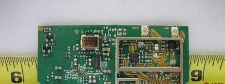
Click to zoom
Application Details
- Equipment Class
- DTS - Digital Transmission System
- Date of Grant
- May 09, 2006
- Application Purpose
- Original Equipment
- Date of Application
- May 09, 2006
- Equipment Note
- WIRELESS 7411 PRINTER SERVER
- Frequency Range
- 2412.00000000 - 2462.00000000
- Country
- United States
Documents & Files
Document Text
Text extracted from the exhibit documents filed with the FCC. Open a document above to read the original.
Users Manual
Preliminary Installation Manual 1 Chung Nam Electronics (CNE) IEEE 802.11a/b/g MiniPCI WLAN Card Installation Manual Version 0.2 June 2004 Preliminary Installation Manual 2 Table of Contents Chapter 1 Introduction............................................................... 3 Chapter 2 Installation Procedure................................ 4 2.1 Installing the software drivers on MS Windows platform...............4 2.2 Configuration..............................................................................................7 2.3 Wireless LAN Installation Guidelines and Authorization for Use .............................................................................................................................. 11 Chapter 3 Regulatory Information........................ 12 3.1 FCC Information to User.......................................................................12 3.2 FCC Guidelines for Human Exposure................................................12 3.3 FCC Electronic Emission Notices.......................................................12 3.4 FCC Radio Frequency Interference Statement.................................13 3.5 Export Restrictions..................................................................................13 Chapter 4 Technical Specifications...................... 14 Preliminary Installation Manual 3 Chapter 1 Introduction The CNE 802.11a/b/g WLAN NIC is a complete wireless high speed Network Interface Card (NIC). It conforms to the IEEE 802.11a and IEEE 802.11g protocol and operates in both the 2.45GHz and 5GHz ISM frequency bands. It provides a complete reference design evaluation platform of hardware and software to system providers or integrators requiring wireless data communications capability and is ideal for integration into computer platforms. y Fully compliant with the IEEE 802.11a, 802.11b and 802.11g WLAN standards y FCC Certified Under Part 15 (pending) to Operate in the 2.45GHz and 5GHz Bands y Support for 54, 48, 36, 24, 18, 12, 9, and 6 Mbps OFDM, 11 and 5.5 Mbps CCK and legacy 2 and 1 Mbps data rates y Driver Supports Microsoft Windows XP and 2000 (SR1) Preliminary Installation Manual 4 Chapter 2 Installation Procedure 2.1 Installing the software drivers on MS Windows platform The driver installation procedure on MS Windows platform is described as follows. Windows XP is used as the example. It is similar in other Windows platform (e.g. Windows 2000). 1. Make sure that the miniPCI card has been inserted in your machine properly. 2. Switch on your machine and boot up to Windows XP. 3. After the system is boot-up, the new miniPCI card is detected automatically. Choose “Install from a list or specific location (Advanced)” and click “Next”. Fig. 1 Preliminary Installation Manual 5 4. Load the appropriate driver file (Install\PRISMA00.inf) from the folder of the driver you just unzipped to (e.g. C:\driver) as shown below. Click “Next” button. Fig. 2 5. A warning dialog may appear as below. Click “Continue Anyway” button to continue the installation. Fig. 3 Preliminary Installation Manual 6 6. The driver installation starts. Fig. 4 7. After the installation, click “Finish” button to exit the installation wizard. Fig. 5 8. Restart Windows. Preliminary Installation Manual 7 2.2 Configuration 1. After the driver is installed, the network icon of the Wireless Connection will appear in the system tray on the bottom right of the screen Fig. 6 2. Right click the WLAN icon and select “Properties” to open the Wireless Network Connection Properties, the following window will appear Fig. 7 Preliminary Installation Manual 8 3. Click the “Configure...” button to enter the miniPCI Adaptor Properties pages. Fig. 8 4. Click on the Advanced tab and change the settings for the wireless connection (e.g. configuration profile, nitro mode settings etc.) Fig. 9 Preliminary Installation Manual 9 5. Click on the Status tab to monitor the connection status Fig. 10 6. Click on the Bands tab to select the frequency band (2.4GHz or 5GHz) and channels. Fig. 11 Preliminary Installation Manual 10 7. Click on the Domain tab to select the Countries/Domain setting Fig. 12 8. Click on the About tab to see the software drivers versions and MAC address Fig. 13 Preliminary Installation Manual 11 2.3 Wireless LAN Installation Guidelines and Authorization for Use Installation and use of this Wireless LAN device must be in strict accordance with the instructions included in the user documentation provided with the product. Any changes or modifications made to this device that are not expressly approved by Chung Nam Electronics (CNE) may void the user’s authority to operate the equipment. CNE is not responsible for any radio or television interference caused by unauthorized modification of this device, or the substitution or attachment of connecting cables and equipment other than specified. It is the responsibility of the user to correct any interference caused by such unauthorized modification, substitution or attachment. CNE and its authorized resellers or distributors will assume no liability for any damage or violation of government regulations arising from failing to comply with these guidelines. The use of Wireless LAN devices may be restricted in some situations or environments for example: y On board airplanes, or y In an explosive environment, or y In case the interference risk to other devices or services is perceived or identified as harmful. In case the policy regarding the use of Wireless LAN devices in specific organizations or environments (e.g. airports, hospitals, chemical/oil/gas industrial plants, private buildings etc.) is not clear, please first verify authorization to use these devices prior to operating the equipment. Preliminary Installation Manual 12 Chapter 3 Regulatory Information 3.1 FCC Information to User This product does not contain any user serviceable components and is to be used with approved antennas only. Any product changes or modifications will…
Text truncated - open the document above for the full version.
Attestation Statements
Paxar Americas, Inc. 170 Monarch Lane Miamisburg, OH 45342 800 543-6650 FAX 937-865-2048 Federal Communications Commission 7435 Oakland Mills Road Columbia, MD 21046 April 27, 2006 Ref: FCC ID: GU6CNWLG500 TIMCO Engineering, Inc. 849 NW State Road 45 Newberry, Florida 32669 To Whom It May Concern: The intent of this modular certification is to allow the use of Chung Nam 802.11b/g miniPCI card and our antennas in any of our printers without re-certification. This will allow the cards to all have the same FCC ID on them, instead of us having to stock under different numbers with different FC Ids. We will only sell it in our printers where we have full control. If you have any questions or concerns, please contact me by email at [email protected]; phone at 1-937-865-2020; or by fax at 1-937-865-2048. Sincerely, James A. Bacher cc: H. Dayton Senior Engineer J. Duckett Paxar Americas, Inc. L. Neuhard A division of Paxar Corp.
Cover Letter(s)
Paxar Americas, Inc. 170 Monarch Lane Miamisburg, OH 45342 800 543-6650 FAX 937-865-2048 Federal Communications Commission 7435 Oakland Mills Road Columbia, MD 21046 April 27, 2006 Ref: FCC ID: GU6CNWLG500 / DA 00-1407 Released: June 26, 2000 PART 15 UNLICENSED MODULAR TRANSMITTER APPROVAL To Whom It May Concern: Our FCC ID: GU6CNWLG500 wireless card can be used inside any device that has a mini PCI slot. It is the intention of the Paxar not to sell it on it’s own, but to use it only in our own print servers and products. Modular Approval allows the card to maintain the same FCC ID and labeling as it is used in other Paxar products. Below are the eight elements a module is required to meet to comply with Part 15, Unlicensed Modular Approval notice, DA 00-1407, dated June 26, 2000. Also included are my arguments on why our module meets the requirements. 1. The modular transmitter must have its own RF shielding. This is intended to ensure that the module does not have to rely upon the shielding provided by the device into which it is installed in order for all modular transmitter emissions to comply with Part 15 limits. It is also intended to prevent coupling between the RF circuitry of the module and any wires or circuits in the device into which the module is installed. Such coupling may result in non-compliant operation. • The Transmitter provided by Chung Nam Electronics is provided with an enclosure that provides the required shielding. 2. The modular transmitter must have buffered modulation/data inputs (if such inputs are provided) to ensure that the module will comply with Part 15 requirements under conditions of excessive data rates or over-modulation. • The inputs are buffered CMOS and the data is processed by a microprocessor in the Chung Nam Electronics module, thereby eliminating excessive data rates or over modulation. 3. The modular transmitter must have its own power supply regulation. This is intended to ensure that the module will comply with Part 15 requirements regardless of the design of the power supplying circuitry in the device into which the module is installed. • The module has it’s own on board regulator and will be supplied a regulated +5 volts in our final products. 4. The modular transmitter must comply with the antenna requirements of Section 15.203 and 15.204(c). The antenna must either be permanently attached or employ a “unique” antenna coupler (at all connections between the module and the antenna, including the cable). Any antenna used with the module must be approved with the module, either at the time of initial authorization or through a Class II permissive change. The “professional installation” provision of Section 15.203 may not be applied to modules. • The antenna coax uses SMT (U.FL) and SMA Reverse Threaded connectors. 5. The modular transmitter must be tested in a stand-alone configuration, i.e., the module must not be inside another device during testing. This is intended to demonstrate that the module is capable of complying with Part 15 emission limits regardless of the device into which it is eventually installed. Unless the transmitter module will be battery powered, it must comply with the AC line conducted requirements found in Section 15.207. AC or DC power lines and data input/output lines connected to the module must not contain ferrites, unless they will be marketed with the module (see Section 15.27(a)). The length of these lines shall be length typical of actual use or, if that length is unknown, at least 10 centimeters to insure that there is no coupling between the case of the module and supporting equipment. Any accessories, peripherals, or support equipment connected to the module during testing shall be unmodified or commercially available (see Section 15.31(i)). • Paxar tested the 802.11b/g module outside of our printer during the tests at Seimic Labs. It was powered by an external 5 volt supply. In our products it will be tied to regulated power sources. 6. The modular transmitter must be labeled with its own FCC ID number, and, if the FCC ID is not visible when the module is installed inside another device, then the outside of the device into which the module is installed must also display a label referring to the enclosed module. This exterior label can use wording such as the following: “Contains Transmitter Module FCC ID: XYZMODEL1” or “Contains FCC ID: XYZMODEL1.” Any similar wording that expresses the same meaning may be used. The Grantee may either provide such a label, an example of which must be included in the application for equipment authorization, or, must provide adequate instructions along with the module which explain this requirement. In the latter case, a copy of these instructions must be included in the application for equipment authorization. • This module will only be used in Paxar printers and will be under Paxar control. • We will include the required external label as well as label the module. 7. The modular transmitter must comply with any specific rule or operating requirements applicable to the transmitter and the manufacturer must provide adequate instructions along with the module to explain any such requirements. A copy of these instructions must be included in the application for equipment authorization. For example, there are very strict operational and timing requirements that must be met before a transmitter is authorized for operation under Section 15.231. For instance, data transmission is prohibited, except for operation under Section 15.231(e), in which case there are separate field strength level and timing requirements. Compliance with these requirements must be assured. • All of the timing is controlled by software in the Chung Nam Electronics unit and is not adjustable by the user. 8. The modular transmitter must comply with any applicable RF exposure requirements. For example, FCC Rules in Sections 2.1091, 2.1093 and specific Sections of Part 15, including 15.319(i), 15.407(f), 15.…
Text truncated - open the document above for the full version.
Cover Letter(s)
Paxar Americas, Inc. 170 Monarch Lane Miamisburg, OH 45342 800 543-6650 FAX 937-865-2048 Federal Communications Commission 7435 Oakland Mills Road Columbia, MD 21046 May 04, 2006 Ref: FCC ID: GU6CNWLG500 TIMCO Engineering, Inc. 849 NW State Road 45 Newberry, Florida 32669 To Whom It May Concern: The following information is to be held confidential pursuant of 47 CFR Part 0 §0.459 and Section 552(b)(4) of the Freedom of Information Act, because the information provided contains trade secrets and is proprietary. If made public, the information might be used to the disadvantage of the applicant in the market place. • Schematics • Theory of Operation • Block Diagram • BOM If you have any questions or concerns, please contact me by email at [email protected]; phone at 1-937-865-2020; or by fax at 1-937-865-2048. Sincerely, James A. Bacher Senior Engineer Paxar Americas, Inc. A division of Paxar Corp. cc: H. Dayton J. Duckett L. Neuhard
External Photos
EXTERNAL PHOTO Front Side Without Shield Back Side
ID Label/Location Info
External ID Label/Location Sample
ID Label/Location Info
ID Label/Location Sample
Internal Photos
INTERNAL PHOTO Front Side Without Shield Back Side
RF Exposure Info
MPE CALCULATION For PAXAR – 802.11b/g Module; Part Number: 126720 RF Exposure Requirements: 47 CFR §1.1307(b) RF Radiation Exposure Limits: 47 CFR §1.1310 RF Radiation Exposure Guidelines: FCC OST/OET Bulletin Number 65 EUT Frequency Band: 2412 – 2462 MHz EUT Maximum Measured Conducted Power: 20.2 dBm (0.1047 watt) EUT Antenna Gain: 2.2 dBi (1.66 numeric) Limits for General Population/Uncontrolled Exposure: 1500 – 100,000 MHz Power Density Limit: 1.0 mW/cm 2 or 10 W/m 2 Equation: S = PG / 4πR 2 or R = √PG / 4πS Where, S = Power Density P = Power Input to Antenna G = Antenna Gain R = distance to the center of radiated antenna S = 0.1047W*1.66 / 4*3.14*(0.2m) 2 = 0.1738W / 0.503m 2 = 0.3458 W/m 2 (0.03458 mW/cm 2 ) EUT comply with 20cm distance exposure.
Test Report
TEST REPORT FROM FOR 802.11b/g Module Part Number: 126720 TO 47 CFR 15.247:2005 & RSS-210 Issue 6:2005 Test Report Serial No.: SL06041101-PAX-007 This report supersedes None Remarks: Equipment complied with the specification [X ] Equipment did not comply with the specification [ ] This Test Report is Issued Under the Authority of: .......................................................................................................... Tested by: Kerwinn Corpuz, Test Engineer .......................................................................................................... Reviewed by: Leslie Bai, Lab Manager Issue date: 11 April 2006 Manufacturer: Paxar Americas, Inc. This test report may be reproduced in full only. NVLAP Lab Code: 200729-0 Registration No. 783147 Registration No. 4842 RTA No. D23/16V Lab Code: KR0032 Title: Paxar Americas, Inc. FCCID: GU6CNWLG500 To: 47 CFR 15.247:2005 & RSS-210 Issue 6:2005 Serial# SL06041101-PAX-007 Issue Date 11 April 2006 Page 2 of 50 www.siemic.com This page has been left blank intentionally. Title: Paxar Americas, Inc. FCCID: GU6CNWLG500 To: 47 CFR 15.247:2005 & RSS-210 Issue 6:2005 Serial# SL06041101-PAX-007 Issue Date 11 April 2006 Page 3 of 50 www.siemic.com CONTENTS EXECUTIVE SUMMARY..............................................................................................................................................5 1 TECHNICAL DETAILS..........................................................................................................................................6 2 TESTS REQUIRED..................................................................................................................................................7 3 ANTENNA REQUIREMENT..................................................................................................................................8 4 MEASUREMENTS, EXAMINATIONS AND DERIVED RESULTS.................................................................9 5 TEST INSTRUMENTATION................................................................................................................................42 APPENDIX A: EUT TEST CONDITIONS.................................................................................................................43 APPENDIX B: EXTERNAL PHOTOS........................................................................................................................44 APPENDIX C: CIRCUIT/BLOCK DIAGRAMS.......................................................................................................45 APPENDIX D: INTERNAL PHOTOS.........................................................................................................................46 APPENDIX E: PRODUCT DESCRIPTION...............................................................................................................47 APPENDIX F: FCC LABEL LOCATION..................................................................................................................48 APPENDIX G: USER MANUAL.................................................................................................................................49 Title: Paxar Americas, Inc. FCCID: GU6CNWLG500 To: 47 CFR 15.247:2005 & RSS-210 Issue 6:2005 Serial# SL06041101-PAX-007 Issue Date 11 April 2006 Page 4 of 50 www.siemic.com This page has been left blank intentionally. Title: Paxar Americas, Inc. FCCID: GU6CNWLG500 To: 47 CFR 15.247:2005 & RSS-210 Issue 6:2005 Serial# SL06041101-PAX-007 Issue Date 11 April 2006 Page 5 of 50 www.siemic.com Executive Summary The purpose of this test programme was to demonstrate compliance of the Paxar Americas, Inc., 802.11b/g Module, part number: 802.11b/g Module against the current 47 CFR 15.247:2005 & RSS- 210 Issue 6:2005. The 802.11b/g Module demonstrated compliance with the 47 CFR 15.247:2005 & RSS-210 Issue 6:2005. Paxar Americas, Inc. is the applicant and claimed manufacturer of this tested product. For the detailed description of this product, please refer to the 802.11b/g Module User Manual. The equipment under test is a DTS system operating in the 2400 – 2483.5 MHz band. The equipment was tested with two modulations: 1) 802.11b with 11Mbps; typically bit rates of 1 to 11Mbps (worse case at 11Mbps). 2) 802.11g with 12Mbps; typically bit rates of 12 to 54Mbps (worse case at 12Mbps). The equipment was tested with the following antenna: HyperLink Technologies, model HG2402RD-RSF; 2.2 dBi Dipole antenna The test has demonstrated that this unit complies with stipulated standards. Radio Module Sample Title: Paxar Americas, Inc. FCCID: GU6CNWLG500 To: 47 CFR 15.247:2005 & RSS-210 Issue 6:2005 Serial# SL06041101-PAX-007 Issue Date 11 April 2006 Page 6 of 50 www.siemic.com 1 Technical Details Purpose Compliance testing of 802.11b/g Module with 47 CFR 15.247:2005 & RSS-210 Issue 6:2005 Applicant / Client Paxar Americas, Inc. 170 Monarch Lane Miamisburg, OH 45342 Manufacturer Paxar Americas, Inc. Laboratory performing the tests SIEMIC Labs 2206 Ringwood Avenue San Jose, CA 95131 Test location(s) SIEMIC Labs 2206 Ringwood Avenue San Jose, CA 95131 Test report reference number SL06041101-PAX-007 Date EUT received 13 April 2006 Standard applied 47 CFR 15.247:2005 & RSS-210 Issue 6:2005 Dates of test (from – to) 18 April 2006 to 19 April 2006 No of Units: 1 Equipment Category: DSS Trade/Product Name: Monarch Part Number: 126720 Technical Variants: none FCC ID No. GU6CNWLG500 IC ID No. 1502A-CNWLG500 Title: Paxar Americas, Inc. FCCID: GU6CNWLG500 To: 47 CFR 15.247:2005 & RSS-210 Issue 6:2005 Serial# SL06041101-PAX-007 Issue Date 11 April 2006 Page 7 of 50 www.siemic.com 2 Tests Required The product was tested in accordance with the following specifications. The test results recorded in this Test Report are exclusively referred to the tested sample(s). Test Standard Description Pass / Fail 47 CFR Part 15.247: 2005 RSS 210 Issue6: 2005 15.203 Antenna Requirement Pass 15.205 RSS210(A8.5) Restricted …
Text truncated - open the document above for the full version.
Test Setup Photos
TEST SETUP PHOTOS Conducted Measurement Setup Radiated Emissions below 1GHz Setup Radiated Emissions above 1GHz Setup Conducted Emissions Voltage Setup
Contact Information
Applicant
Michael Ouziel(Regulatory Engineer)
Test Firm
SIEMIC LaboratoriesLeslie Bai
Technical Specifications
| # | Rule Parts | Frequency Range | Power Output |
|---|---|---|---|
| 1 | 15C | 2.41 GHz - 2.46 GHz | 105.00 mW |
Other Applications from Avery Dennison Retail Information Services, LLC
GU6WTB4010
Aug 25, 2021ZippyYum Thermometer
Equipment Class
DTS - Digital Transmission System
GU6-QUATECH1
Oct 04, 2015Mobile PrinterModel name - 9485NP
Equipment Class
DTS - Digital Transmission System
GU6-RS500GX
Aug 13, 2014UHF RFID Module
Equipment Class
DSS - Part 15 Spread Spectrum Transmitter
GU6-QUATECH
Oct 04, 2012MOBILE PRINTER
Equipment Class
JBP - Part 15 Class B Computing Device Peripheral
GU6-MTT
Oct 04, 2012MOBILE PRINTER
Equipment Class
JBP - Part 15 Class B Computing Device Peripheral