GU6WJSX2000ARFID Module
Avery Dennison Retail Information Services, LLC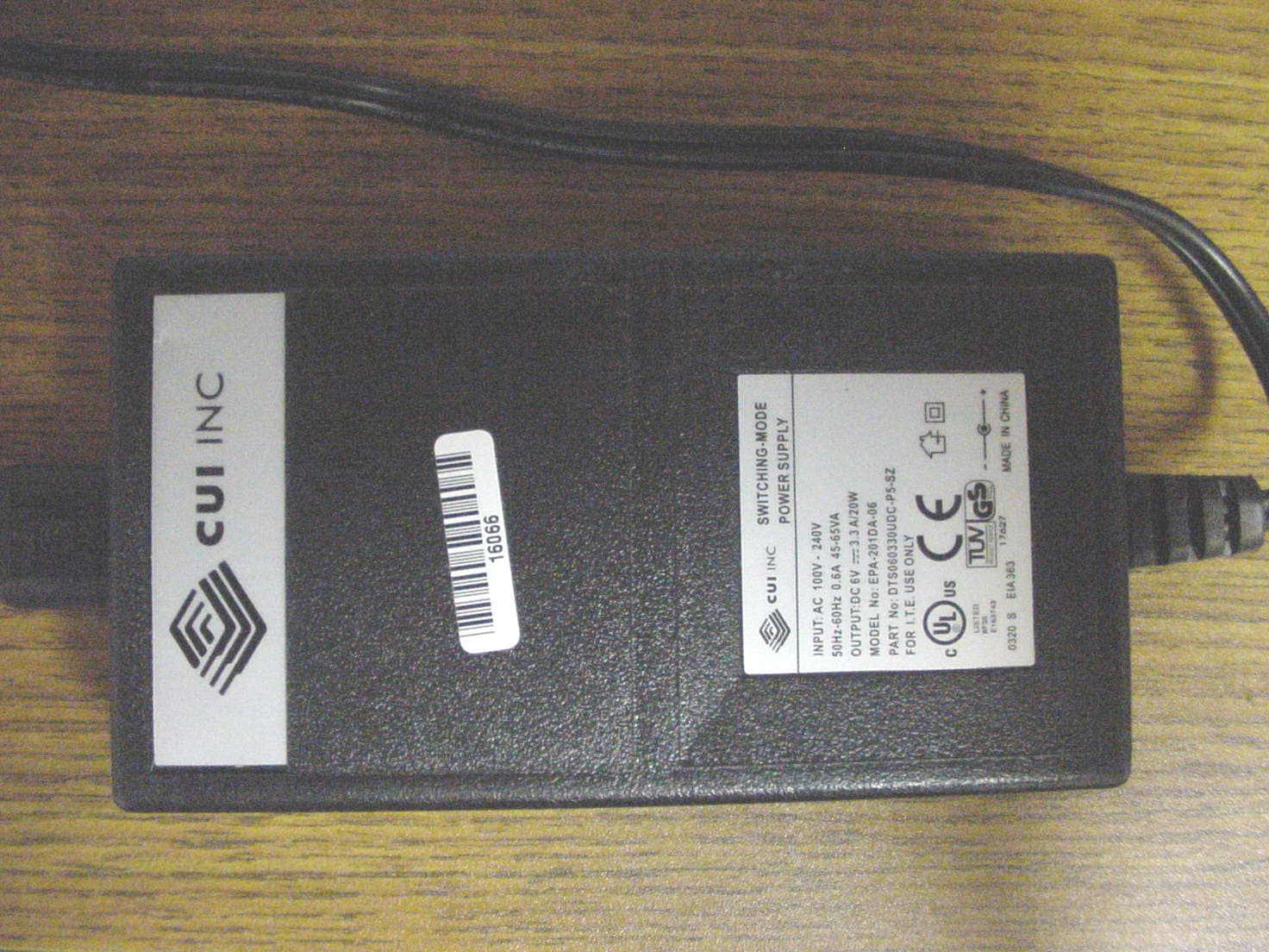
Click to zoom
Application Details
- Equipment Class
- DSS - Part 15 Spread Spectrum Transmitter
- Date of Grant
- Aug 04, 2004
- Application Purpose
- Original Equipment
- Date of Application
- Aug 04, 2004
- Equipment Note
- RFID Module
- Frequency Range
- 902.80000000 - 927.60000000
- Country
- United States
Documents & Files
Document Text
Text extracted from the exhibit documents filed with the FCC. Open a document above to read the original.
Users Manual
Rhein Tech Laboratories Client: Paxar Americas, Inc. 360 Herndon Parkway FCC: Part 15.247 Suite 1400 Industry Canada: RSS-210 FCC ID: GU6WJSX2000A Herndon, VA 20170 http://www.rheintech.com Model : ALR-9932-B Page 44 of 59 APPENDIX I: MANUAL Please refer to the following pages. Monarch 9855 RFID Printer TC9855RFIDQR Rev. AA 3/04 ©2004 Paxar Americas, Inc. All rights reserved. BETA Each product and program carries a respecti ve written warranty, the only warranty on which the customer can rely. Paxar re serves the right to make changes in the product, the programs, and their availabilit y at any time and without notice. Although Paxar has made every effort to provide complete and accurate information in this manual, Paxar shall not be liable for any omissions or inaccuracies. Any update will be incorporated in a later edition of this manual. 2004 Paxar Americas, Inc. All rights reserv ed. No part of this publication may be reproduced, transmitted, stored in a retr ieval system, or translated into any language in any form by any means, without the prior written permission of Paxar Americas, Inc. WARNING This equipment has been tested and found to comply wi th the limits for a Class A digital device, pursuant to Part 15 of the FCC Rules. These limits are designed to prov ide reasonable protection against harmful interference when the equipment is operated in a commercial environment. This equipment generates, uses, and can r adiate radio frequency energy and, if not installed and used in accordance with the instruction manual, may cause harmful interference to radio communications. Operation of this equipment in a residential area is likely to cause harmful in terference in which case the user will be required to correct the interference at his own expense. CANADIAN D.O.C. WARNING This digital apparatus does not exceed the Class A limits for radio noise em issions from digital apparatus set out in the Radio Interference Regulations of the Canadian Department of Communications. Le présent appareil numérique n'ém et pas de bruits radioélectr iques dépassant les limites applicables aux appareils numériques de la classe A prescrites dans le Réglement sur le brouillage radioélectrique édicte par le mini stère des Communications du Canada. Regulatory Compliance Paxar RF products are designed to be compliant with the rules and regulations in the locations into which they are sold and will be labeled as required. The majority of Paxar RF devices are type approved and do not require the user to obtain license or authorization before using the equipment. Any changes or modifications to Paxar equipment not expressly approved by Paxar could void the user authority to operate the equipment. FCC RF Exposure Guidelines To comply with FCC exposure requirement s, antennas that are mounted externally at remote locations or operating near users at stand-alone desktop of similar configurations must operate with a minimu m separation distance of 20 cm from all persons. Declaration of Conformity for RF Exposure: The radio module has been evaluated under FCC Bulletin OET 65C and found compliant to the requirements as set fo rth in CFR 47 Sections 2.1091, 2.1093, and 15.247 (b) (4) addressing RF Exposure from radio frequency devices. Radio Frequency Interference Requirements This device complies with Part 15 of the F CC Rules. Operation is subject to the following two conditions: 1) this device ma y not cause harmful interference, and 2) this device must accept any interfer ence that may cause undesired operations. CAUTION: The Part 15 radio device operates on a non-i nterference basis with other devices operating at this frequency when using the listed antenna. Collocation Statement: This device must not be collocated wi th any other antenna or transmitters. Radio Frequency Interference Requirements - Canada This device complies with RSS 210 of Industr y Canada. Operation is subject to the following two conditions: (1) this device ma y not cause harmful interference and (2) this device must accept any interference received, including interference that may cause undesired operation. This Class A digital apparatus meet s the requirements of the Canadian Interference-Causing Equipment Regulations. Cet appareil numérique de la Classe A especte toutes les exigencies du Reglement sur le Materiél Brouilleur du Canada. Trademarks Monarch is a registered trademark of Paxar Americas, Inc. 9855 is a trademark of Paxar Americas, Inc. Paxar is a trademark of Paxar Corporation. Paxar Americas, Inc. 170 Monarch Lane Miamisburg, OH 45342 Visit www.paxar.com for sales, service, supplies, information, and telephone numbers for our locations throughout the world. TOLL FREE: 1-800-543-6650 (U.S.A.) 1-800-363-7525 (Canada) 1 This Quick Reference contains supply loading and general care and maintenance procedures. For more detailed information, the Operator’s Handbook is on the optional Tabletops Documentation CD-ROM or can be downloaded from our Web site. Check the Web site for the latest release/addendum information. Connecting the Cables The power supply automatically switc hes between 115V or 230V. There are no operator settings required. 1. Plug the power cable into the socket. Plug the other end of the cable into a grounded electrical outlet. 2. Connect the communication cable into the appropriate port. Secure the cable with the connecting screws (serial) or spring clips (parallel). If you are communicating with the host through the serial port, make sure the printer's communication values match those at the host. The factory default values are 9600 Baud, 8 bit data frame, 1 stop bit, no parity, and DTR flow control. Set the communication values on the printer to match those at the host. The printer also has a USB (Universal Serial Bus) Version 1.1 communications port. Drivers are available on our Web site for a variety of operating systems. 3. Turn on the printer. Press ( I ) to turn on and ( O ) to turn off the print…
Text truncated - open the document above for the full version.
Cover Letter(s)
Rhein Tech Laboratories Client: Paxar Americas, Inc. 360 Herndon Parkway FCC: Part 15.247 Suite 1400 Industry Canada: RSS-210 FCC ID: GU6WJSX2000A Herndon, VA 20170 http://www.rheintech.com Model : ALR-9932-B Page 38 of 59 APPENDIX C: AGENCY AUTHORIZATION LETTER Please refer to the following page. Paxar Americas, Inc. 170 Monarch Lane Miamisburg, OH 45342 800 543-6650 FAX 937-865-2048 February 26, 2004 American TCB, Inc. 6731 Whittier Avenue Suite C110 McLean, VA 22101 Re: Agent Authorization To Whom It May Concern: Paxar Americas, Inc. hereby authorizes Rhein Tech Laboratories, Inc. (RTL), 360 Herndon Parkway, Suite 1400, Herndon, VA 20170 to act as agent. APPLICANT ANTI-DRUG ABUSE CERTIFICATION: In signing this letter, Applicant certifies that, in the case of an individual applicant, he or she is not subject to a denial of federal benefits, that includes: FCC benefits, pursuant to Section 5301 of the Anti-Drug Abuse Act of 1988, 21 U.S.C. 853(a), or, in the case of a non-individual applicant. No party to the application is subject to a denial of federal benefits that includes FCC benefits, pursuant to that section. For the definition of a “party” for these purposes, see 47 CFR 1.2002(b). If you have any questions or concerns, please contact me by email at [email protected]; phone at 1-937-865-2020; or by fax at 1-937-865-2048. Sincerely, James A. Bacher Senior Engineer Paxar Americas, Inc. A division of Paxar Corp. cc: H. Dayton J. Duckett L. Neuhard
Cover Letter(s)
Rhein Tech Laboratories Client: Paxar Americas, Inc. 360 Herndon Parkway FCC: Part 15.247 Suite 1400 Industry Canada: RSS-210 FCC ID: GU6WJSX2000A Herndon, VA 20170 http://www.rheintech.com Model : ALR-9932-B Page 39 of 59 APPENDIX D: CONFIDENTIALITY REQUEST LETTER Please refer to the following page. Paxar Americas, Inc. 170 Monarch Lane Miamisburg, OH 45342 800 543-6650 FAX 937-865-2048 March 04, 2004 American TCB, Inc. 6731 Whittier Avenue Suite C110 McLean, VA 22101 To Whom It May Concern: The following information is to be held confidential pursuant of 47 CFR Part 0 §0.459 and Section 552(b)(4) of the Freedom of Information Act, because the information provided contains trade secrets and is proprietary. If made public, the information might be used to the disadvantage of the applicant in the market place. • Schematics • Technical Product Description • Block Diagram If you have any questions or concerns, please contact me by email at [email protected]; phone at 1-937-865-2020; or by fax at 1-937-865-2048. Sincerely, James A. Bacher Senior Engineer Paxar Americas, Inc. A division of Paxar Corp. cc: H. Dayton J. Duckett L. Neuhard
Cover Letter(s)
Rhein Tech Laboratories Client: Paxar Americas, Inc. 360 Herndon Parkway FCC: Part 15.247 Suite 1400 Industry Canada: RSS-210 FCC ID: GU6WJSX2000A Herndon, VA 20170 http://www.rheintech.com Model : ALR-9932-B Page 37 of 59 APPENDIX B: ATTESTATION – DA 00-1407 MODULAR APPROVAL Please refer to the following page. Paxar Americas, Inc. 170 Monarch Lane Miamisburg, OH 45342 800 543-6650 FAX 937-865-2048 March 15, 2004 Reference: DA 00-1407 Released: June 26, 2000 PART 15 UNLICENSED MODULAR TRANSMITTER APPROVAL American TCB, Inc. 6731 Whittier Avenue Suite C110 McLean, VA 22101 To Whom It May Concern: Below are the eight elements a module is required to meet to comply with Part 15, Unlicensed Modular Approval notice, DA 00-1407, Dated June 26, 2000. Also included are my arguments on why our module meets the requirements. 1. The modular transmitter must have its own RF shielding. This is intended to ensure that the module does not have to rely upon the shielding provided by the device into which it is installed in order for all modular transmitter emissions to comply with Part 15 limits. It is also intended to prevent coupling between the RF circuitry of the module and any wires or circuits in the device into which the module is installed. Such coupling may result in non-compliant operation. a. The Transmitter provided by Watkins Johnson is provided with an enclosure that provides the required shielding. 2. The modular transmitter must have buffered modulation/data inputs (if such inputs are provided) to ensure that the module will comply with Part 15 requirements under conditions of excessive data rates or over-modulation. a. The inputs are buffered RS232 and the data is processed by a microprocessor in the Watkins Johnson module, thereby eliminating excessive data rates or over modulation. 3. The modular transmitter must have its own power supply regulation. This is intended to ensure that the module will comply with Part 15 requirements regardless of the design of the power supplying circuitry in the device into which the module is installed. a. We provide an I/O board that regulates the supply voltage from 24 volts down to the 6 volts the Watkins Johnson transmitter needs. 4. The modular transmitter must comply with the antenna requirements of Section 15.203 and 15.204(c). The antenna must either be permanently attached or employ a “unique” antenna coupler (at all connections between the module and the antenna, including the cable). Any antenna used with the module must be approved with the module, either at the time of initial authorization or through a Class II permissive change. The “professional installation” provision of Section 15.203 may not be applied to modules. a. The antenna uses MMCX connectors. In this application the customer will never change the antenna. The reason is, if they change it to a higher gain antenna, they will program more than one tag at a time, which will prevent their RFID tags from working properly. 5. The modular transmitter must be tested in a stand-alone configuration, i.e., the module must not be inside another device during testing. This is intended to demonstrate that the module is capable of complying with Part 15 emission limits regardless of the device into which it is eventually installed. Unless the transmitter module will be battery powered, it must comply with the AC line conducted requirements found in Section 15.207. AC or DC power lines and data input/output lines connected to the module must not contain ferrites, unless they will be marketed with the module (see Section 15.27(a)). The length of these lines shall be length typical of actual use or, if that length is unknown, at least 10 centimeters to insure that there is no coupling between the case of the module and supporting equipment. Any accessories, peripherals, or support equipment connected to the module during testing shall be unmodified or commercially available (see Section 15.31(i)). a. Paxar tested the RFID module outside of our printer during the tests at Rhein Tech. During the tests it was powered by the printers 24VDC power supply, using the Paxar I/O board to further reduce the supply voltage to 6VDC (see note in item 3 above). 6. The modular transmitter must be labeled with its own FCC ID number, and, if the FCC ID is not visible when the module is installed inside another device, then the outside of the device into which the module is installed must also display a label referring to the enclosed module. This exterior label can use wording such as the following: “Contains Transmitter Module FCC ID: XYZMODEL1” or “Contains FCC ID: XYZMODEL1.” Any similar wording that expresses the same meaning may be used. The Grantee may either provide such a label, an example of which must be included in the application for equipment authorization, or, must provide adequate instructions along with the module which explain this requirement. In the latter case, a copy of these instructions must be included in the application for equipment authorization. a. This module will only be used in Paxar printers and will be under Paxar control. We will include the required external label as well as label the module. 7. The modular transmitter must comply with any specific rule or operating requirements applicable to the transmitter and the manufacturer must provide adequate instructions along with the module to explain any such requirements. A copy of these instructions must be included in the application for equipment authorization. For example, there are very strict operational and timing requirements that must be met before a transmitter is authorized for operation under Section 15.231. For instance, data transmission is prohibited, except for operation under Section 15.231(e), in which case there are separate field strength level and timing requirements. Compliance with these requirements must be assured. a. All of the timing is controlled by software in the Watkins Johnson unit and is not adjusta…
Text truncated - open the document above for the full version.
Cover Letter(s)
American Telecommunications Certification Body Inc. 6731 Whittier Ave, McLean, VA 22101 August 19, 2004 RE: Paxar Corporation FCC ID: GU6WJSX2000A I have a few comments on this Application. 1.) The antenna cable appears to contain a removable 9 dB attenuation. Given this application is for modular approval, how can integration of this attenuator into all units be assured (i.e., will the connection be made permanent, will only the applicant or their OEM integrator install this device, etc. Response : Per section 1.3 of the test report, this application is for “limited modular approval” and Paxar will maintain control of all host devices. Since the application is for “limited modular approval”, Paxar will ensure that the 9 dB attenuation is installed in all end products. 2.) AC power line emissions must meet the limits of 15.207 (equivalent to Class B, not Class A from 15.107). Please correct. Currently peak results exceed the average limits. Please review, correct, and provide additional measurements as necessary. Response : Please see the revised test report uploaded with this response. 3.) Even if the Digital device emissions are only subject to Class A emissions, All emissions caused by the RX (LO’s, LO harmonics, etc.), must meet with limits equivalent to Class B. How was this test performed to ensure that all frequencies from the RX part of the device meet with the more stringent limits? Response : Please note that this device will only be used in commercial, industrial or business environments. Receiver emissions were tested to 15.109 Class B limits; all receiver emissions complied with these limits. Upon clarification from the manufacturer, the digital emissions in question were harmonics from the microprocessor clock (40 MHz). 15.109 Class A limits were applied to these digital emissions; these digital emissions met 15.109 Class A limits. Timothy R. Johnson Examining Engineer Direct Phone: 404-414-8071 mailto: [email protected] The items indicated above must be submitted before processing can continue on the above referenced application. Failure to provide the requested information may result in application termination. Correspondence should be considered part of the permanent submission and may be viewed from the Internet after a Grant of Equipment Authorization is issued. Please do not respond to this correspondence using the email reply button. In order for your response to be processed expeditiously, you must submit your documents through the AmericanTCB.com website. Also, please note that partial responses increase processing time and should not be submitted. Any questions about the content of this correspondence should be directed to the sender.
Cover Letter(s)
From: OET Generic account [[email protected]] Sent: Friday, September 03, 2004 5:43 AM To: [email protected] Subject: audit To: William Graff From: Tim Harrington [email protected] FCC Equipment Authorization Branch Re: FCC ID: GU6WJSX2000A Applicant: Paxar Americas, Inc. Correspondence Reference Number: 13742 731 Confirmation Number: TC818430 Date of Original Email: 09/03/2004 Subject: audit For MPE exhibit, how is antenna gain of -15.1 dBi determined? Response : The gain was determined using the conducted value 29.5 dBm and radiated field strength value of 99.6 dBuV/m (converted to 4.4 dBm). The value 29.5 dBm minus the 9 dB in-line attenuator, and the 1 dB cable loss to the antenna, yields 19.5 dBm, minus the 4.4 dBm value from the field strength conversion, resulting in a net loss of 15.1 dB for the antenna. The items indicated above must be submitted before processing can continue on the above referenced application. Failure to provide the requested information within 30 days of the original e-mail date may result in application dismissal pursuant to Section 2.917(c). DO NOT Reply to this email by using the Reply button. In order for your response to be processed expeditiously, you must upload your response via the Internet at www.fcc.gov, E- Filing, OET TCB Electronic Filing, TCB Login. If the response is submitted through Add Attachments, a message which informs the processing staff that a new exhibit has been submitted must also be submitted via Submit Correspondence. Also, please note that partial responses increase processing time and should not be submitted. Any questions about the content of this correspondence should be directed to the e-mail address listed below the name of the sender.
External Photos
Rhein Tech Laboratories Client: Paxar Americas, Inc. 360 Herndon Parkway FCC: Part 15.247 Suite 1400 Industry Canada: RSS-210 FCC ID: GU6WJSX2000A Herndon, VA 20170 http://www.rheintech.com Model : ALR-9932-B Page 51 of 59 APPENDIX K: EXTERNAL PHOTOGRAPHS PHOTOGRAPH 8: RFID MODULE FRONT Rhein Tech Laboratories Client: Paxar Americas, Inc. 360 Herndon Parkway FCC: Part 15.247 Suite 1400 Industry Canada: RSS-210 FCC ID: GU6WJSX2000A Herndon, VA 20170 http://www.rheintech.com Model : ALR-9932-B Page 52 of 59 PHOTOGRAPH 9: RFID MODULE BACK Rhein Tech Laboratories Client: Paxar Americas, Inc. 360 Herndon Parkway FCC: Part 15.247 Suite 1400 Industry Canada: RSS-210 FCC ID: GU6WJSX2000A Herndon, VA 20170 http://www.rheintech.com Model : ALR-9932-B Page 53 of 59 PHOTOGRAPH 10: ANTENNA FRONT Rhein Tech Laboratories Client: Paxar Americas, Inc. 360 Herndon Parkway FCC: Part 15.247 Suite 1400 Industry Canada: RSS-210 FCC ID: GU6WJSX2000A Herndon, VA 20170 http://www.rheintech.com Model : ALR-9932-B Page 54 of 59 PHOTOGRAPH 11: ANTENNA BACK
External Photos
Rhein Tech Laboratories Client: Paxar Americas, Inc. 360 Herndon Parkway FCC: Part 15.247 Suite 1400 Industry Canada: RSS-210 FCC ID: GU6WJSX2000A Herndon, VA 20170 http://www.rheintech.com Model : ALR-9932-B Page 55 of 59 PHOTOGRAPH 12: ANTENNA WITH 9 DB ATTENUATOR Rhein Tech Laboratories Client: Paxar Americas, Inc. 360 Herndon Parkway FCC: Part 15.247 Suite 1400 Industry Canada: RSS-210 FCC ID: GU6WJSX2000A Herndon, VA 20170 http://www.rheintech.com Model : ALR-9932-B Page 56 of 59 PHOTOGRAPH 13: INLINE WITH ANTENNA SMA 9 DB ATTENUATOR Rhein Tech Laboratories Client: Paxar Americas, Inc. 360 Herndon Parkway FCC: Part 15.247 Suite 1400 Industry Canada: RSS-210 FCC ID: GU6WJSX2000A Herndon, VA 20170 http://www.rheintech.com Model : ALR-9932-B Page 57 of 59 PHOTOGRAPH 14: POWER SUPPLY
ID Label/Location Info
Rhein Tech Laboratories Client: Paxar Americas, Inc. 360 Herndon Parkway FCC: Part 15.247 Suite 1400 Industry Canada: RSS-210 FCC ID: GU6WJSX2000A Herndon, VA 20170 http://www.rheintech.com Model : ALR-9932-B Page 40 of 59 APPENDIX E: LABEL AND LABEL LOCATION PHOTOGRAPH 1: LABEL LOCATION Please see the following page for a sample of the FCC Identification Label. FCC ID LABEL HERE
Internal Photos
Rhein Tech Laboratories Client: Paxar Americas, Inc. 360 Herndon Parkway FCC: Part 15.247 Suite 1400 Industry Canada: RSS-210 FCC ID: GU6WJSX2000A Herndon, VA 20170 http://www.rheintech.com Model : ALR-9932-B Page 58 of 59 APPENDIX L: INTERNAL PHOTOGRAPHS PHOTOGRAPH 15: ALIEN RFID CARD SIDE 1 Rhein Tech Laboratories Client: Paxar Americas, Inc. 360 Herndon Parkway FCC: Part 15.247 Suite 1400 Industry Canada: RSS-210 FCC ID: GU6WJSX2000A Herndon, VA 20170 http://www.rheintech.com Model : ALR-9932-B Page 59 of 59 PHOTOGRAPH 16: ALIEN RFID CARD SIDE 2 AND INSIDE CASE
RF Exposure Info
Rhein Tech Laboratories Client: Paxar Americas, Inc. 360 Herndon Parkway FCC: Part 15.247 Suite 1400 Industry Canada: RSS-210 FCC ID: GU6WJSX2000A Herndon, VA 20170 http://www.rheintech.com Model : ALR-9932-B Page 36 of 59 APPENDIX A: RF EXPOSURE COMPLIANCE FCC Rules and Regulations Part 1.1307, 1.1310, 2.1091, 2.1093: From FCC 1.1310 Table 1B, the maximum permissible RF exposure for an uncontrolled environment for a device operating at this frequency range is 0.61 mW/cm 2 . The actual power density for the EUT with the antenna is calculated as shown below at 20 cm. The EUT is a mobile device per 2.1091 operating at 902 – 928 MHz. )4/()( 2 dGPS×××=π where: S = power density P = transmitter conducted power in (W) G = antenna numeric gain d = distance to radiation center (m) Antenna Manufacturer/ Model Antenna Type Gain (dBi) Numeric Gain Power (W) Separation Distance (m) Power Density (W/m 2 ) Power Density (mW/cm 2 ) Paxar/BW-S9W2 Dipole -15.1 0.03 .88 0.2 0.05 0.005 WARNING: It is the responsibility of the professional installer to ensure that when using the outdoor antenna in the United States (or where FCC rules apply), only the antenna specified above may be used. The use of any other antenna is expressly forbidden in accordance with FCC rules CFR 47 part 15.204. Proposed RF exposure safety information to include in User’s Manual: CAUTION: Antenna Installation Requirement The antenna(s) used for this transmitter must be installed to provide a separation distance of at least 20 cm from all persons and must not be co-located or operating in conjunction with any other antenna or transmitter.
Test Report
Engineering and Testing for EMC and Safety Compliance 360 Herndon Parkway, Suite 1400 Herndon, VA 20170 Phone: 703-689-0368; Fax: 703-689-2056; Metro: 703-471-6441 CERTIFICATION APPLICATION REPORT FCC PART 15.247 & INDUSTRY CANADA RSS-210 Test Lab: Rhein Tech Laboratories, Inc. Phone: 703-689-0368 360 Herndon Parkway Fax: 703-689-2056 Suite 1400 Web Site: www.rheintech.com Herndon, VA 20170 E-Mail: [email protected] Applicant: Paxar Americas, Inc. Phone: 937-865-2123 x2020 170 Monarch Lane Fax: 937-865-2048 Miamisburg, OH 45342 Email: [email protected] Contact: James A. Bacher FCC ID: GU6WJSX2000A GRANTEE FRN NUMBER: 0003583150 PLAT FORM: N/A RTL WORK ORDER: 2004111 MODEL(S): ALR-9932-B RTL QUOTE NUMBER: QRTL04-237 DATE OF TEST REPORT: August 24, 2004 American National Standard Institute: ANSI C63.4: Methods of Measurement of Radio-Noise Emissions from Low-Voltage Electrical and Electronic Equipment in the Range of 9 kHz to 40 GHz FCC Classification: DSS – Part 15 Spread Spectrum Transmitter Frequency Hopping FCC Rule Part(s): Part 15.247: Operation within the bands 920-928 MHz, 2400-2483.5 MHz and 5725- 5850 MHz Frequency Hopping System Industry Canada Standard: RSS-210: Low Power License-Exempt Radio Communication Devices (All Frequency Bands) Digital Interface Information Digital Interface was found to be compliant Receiver Information Receiver was found to be compliant Frequency Range (MHz) Output Power* (W) Frequency Tolerance Emission Designator 902.8-927.6 0.883 N/A N/A * output power is maximum peak conducted I, the undersigned, hereby declare that the equipment tested and referenced in this report conforms to the identified standard(s) as described in this test report. Furthermore, there was no deviation from, additions to, or exclusions from the FCC Part 2, FCC Part 15, Industry Canada RSS-210, ANSI C63.4, ANSI/TIA/EIA603, and ANSI/TIA/EIA 603-1. Signature: Date: August 24, 2004 Typed/Printed Name: Desmond A. Fraser Position: President Rhein Tech Laboratories Client: Paxar Americas, Inc. 360 Herndon Parkway FCC: Part 15.247 Suite 1400 Industry Canada: RSS-210 FCC ID: GU6WJSX2000A Herndon, VA 20170 http://www.rheintech.com Model : ALR-9932-B Page 2 of 59 TABLE OF CONTENTS 1 GENERAL INFORMATION ........................................................................................................................................................................................... 5 1.1 SCOPE ........................................................................................................................................................................................5 1.2 TEST FACILITY ........................................................................................................................................................................5 1.3 RELATED SUBMITTAL(S)/GRANT(S)...................................................................................................................................5 1.4 MODIFICATIONS .....................................................................................................................................................................5 2 TEST INFORMATION.................................................................................................................................................................................................... 6 2.1 TEST JUSTIFICATION .............................................................................................................................................................6 2.2 EXERCISING THE EUT ............................................................................................................................................................6 2.3 TEST RESULT SUMMARY ......................................................................................................................................................6 2.4 TEST SYSTEM DETAILS .........................................................................................................................................................7 2.5 CONFIGURATION OF TESTED SYSTEM ..............................................................................................................................7 3 COMPLIANCE WITH THE RESTRICTED BAND EDGE – FCC §15.205; IC RSS-210 §6.3....................................................................................... 8 3.1 TEST PROCEDURE...................................................................................................................................................................8 3.2 BAND EDGE TEST EQUIPMENT............................................................................................................................................8 3.3 COMPLIANCE WITH THE RESTRICTED BAND EDGE TEST DATA ................................................................................8 4 CONDUCTED LIMITS – FCC §15.207; IC RSS-210 §6.6 AND 7.4 ........................................................................................................................... 11 4.1 CONDUCTED TEST DATA ....................................................................................................................................................11 5 RADIATED EMISSION LIMITS; SPURIOUS AND HARMONICS – FCC §15.247; IC RSS-210 §6.3....................................................................... 15 5.1 RADIATED SPURIOUS EMISSION LIMITS TEST PROCEDURE......................................................................................15 5.2 RADIATED SPURIOUS TEST EQUIPMENT ........................................................................................................................15 5.3 RADIATED EMISSIONS HARMONICS/SPURIOUS TEST DATA .....................................................................................16 6 CARRIER FREQUENCY SEPARATION - §15.247 (A)(1)......................................................................…
Text truncated - open the document above for the full version.
Test Setup Photos
Rhein Tech Laboratories Client: Paxar Americas, Inc. 360 Herndon Parkway FCC: Part 15.247 Suite 1400 Industry Canada: RSS-210 FCC ID: GU6WJSX2000A Herndon, VA 20170 http://www.rheintech.com Model : ALR-9932-B Page 45 of 59 APPENDIX J: TEST PHOTOGRAPHS PHOTOGRAPH 2: RADIATED EMISSIONS FRONT VIEW (3M) Rhein Tech Laboratories Client: Paxar Americas, Inc. 360 Herndon Parkway FCC: Part 15.247 Suite 1400 Industry Canada: RSS-210 FCC ID: GU6WJSX2000A Herndon, VA 20170 http://www.rheintech.com Model : A…
Text truncated - open the document above for the full version.
Contact Information
Applicant
Michael Ouziel(Regulatory Engineer)
Technical Contact
Rhein Tech Laboratories, Inc.Desmond Fraser
[email protected]703-689-0368
360 Herndon Parkway Suite 1400 · Herndon, Virginia · United States
Test Firm
Rhein Tech Laboratories, Inc.Galina Yushina
Technical Specifications
| # | Rule Parts | Frequency Range | Power Output |
|---|---|---|---|
| 1 | 15C | 902.8 MHz - 927.6 MHz | 900.00 mW |
Other Applications from Avery Dennison Retail Information Services, LLC
GU6WTB4010
Aug 25, 2021ZippyYum Thermometer
Equipment Class
DTS - Digital Transmission System
GU6-QUATECH1
Oct 04, 2015Mobile PrinterModel name - 9485NP
Equipment Class
DTS - Digital Transmission System
GU6-RS500GX
Aug 13, 2014UHF RFID Module
Equipment Class
DSS - Part 15 Spread Spectrum Transmitter
GU6-QUATECH
Oct 04, 2012MOBILE PRINTER
Equipment Class
JBP - Part 15 Class B Computing Device Peripheral
GU6-MTT
Oct 04, 2012MOBILE PRINTER
Equipment Class
JBP - Part 15 Class B Computing Device Peripheral