GZ5NVG558HXFixed Broadband Gateway
ARRIS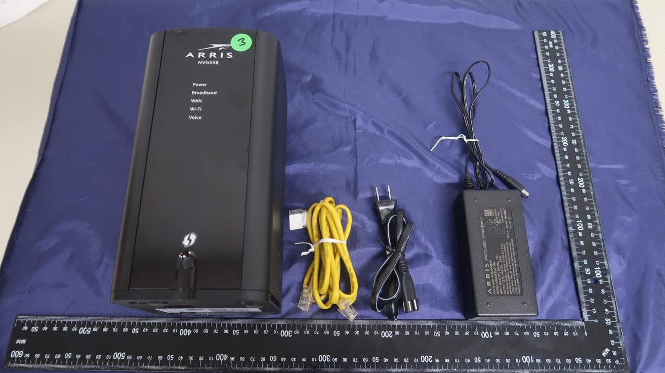
Click to zoom
Application Details
- Equipment Class
- PCB - PCS Licensed Transmitter
- Date of Grant
- Oct 09, 2020
- Application Purpose
- Original Equipment
- Date of Application
- Oct 08, 2020
- Equipment Note
- Fixed Broadband Gateway
- Frequency Range
- 821.50000000 - 821.50000000
- Company
- ARRIS
- Country
- United States
Documents & Files
Document Text
Text extracted from the exhibit documents filed with the FCC. Open a document above to read the original.
Users Manual
Introduction ARRIS NVG558 Gateway Quick Start Guide Use this Quick Start Guide to install, configure, and perform basic troubleshooting for the ARRIS NVG558 gateway. Power supply installation Connect the power supply cord to the Power In connector on the gateway and the other end into an appropriate electrical outlet. Product ventilation The gateway is intended for residential use. Position the gateway in a vertical position and where temperature remains within a range of 32° – 104°F (0° – 40°C) and heat from the unit itself is not trapped. There must be at least two inches (2”) of clearance on all sides except the bottom. Gateway positioning Position the gateway in a vertical position. Proper positioning of the gateway is essential for proper cooling. Status indicator lights and port configuration Colored LEDs on the gateway indicate the status of various port activity. Front panel LEDs LED Status Power Solid Green: The device is powered on. Flashing Green: The device is starting. Solid Red: Boot failure. Flashing Red: Detecting factory reset (press and hold the recessed Reset button for 10 or more seconds to trigger the factory reset). Broadband Solid Blue: Broadband internet connection is active. Solid Red: No IP address or authentication failed. Off: No active broadband connection. WAN NVG558 (with Ethernet WAN interface) Solid Green: Ethernet WAN connection is good. Flashing Green: Trying to connect to the available network. Solid Red: No Ethernet WAN connection on the line. NVG558 (with Cellular WAN interface) Solid Green: Cellular WAN connection is good. Solid Yellow: Cellular WAN connection is fair. Solid Red: Cellular WAN connection is poor. Flashing Red: No cellular WAN connection on the line. Wi-Fi Solid Green: Wireless enabled (either radio). Flashing Yellow: Wi-Fi protected Set-up (WPS) is active. Flashing Red: Flashes for 30 seconds to indicate the timeout or conflict of WPS. Solid Red: Wireless network failure. Off: Wireless is disabled for both the radios. LAN/WAN Ethernet LEDS on rear panel RJ-45 ports Solid Green: Port is active. Off: Port is not active. Flashing Green: Traffic is passing on the line. LED descriptions MPE/SAR/RF exposure information This device was verified for RF exposure and found to comply with FCC OET bulletin 65 RF exposure requirements. This equipment complies with FCC radiation exposure limits set forth for an uncontrolled environment. WARNING: While this device is in operation, a separation distance of at least 30 cm (12 inches) must be maintained between the radiating antennas and the bodies of all persons exposed to the transmitter to meet the FCC RF exposure guidelines. Making changes to the antenna or the device is not permitted. Doing so may result in the installed system exceeding RF exposure requirements. This device must not be co- located or operated in conjunction with any other antenna or radio transmitter. Use of controls or adjustments or performance of procedures other than those specified herein may result in hazardous radiation exposure is required to be in the operating and maintenance instructions. Safety information The following sections describe the safety guidelines for this product. AC adapter This product is intended to be supplied with a listed ARRIS desktop AC adapter marked Class 2 or LPS and rated 100 – 120V, 50/60Hz 1A, Output 12V, 3.75A for all NVG558 series gateway models. The AC power adapter supplied with this product is designed to ensure your personal safety and to be compatible with this equipment. Use only the power adapter that was provided with the gateway. Please follow these guidelines: • Do not use the adapter in a high moisture environment. Never touch the adapter when your hands or feet are wet. • Allow adequate ventilation around the adapter. Avoid locations with restricted airflow. • Connect the adapter to a proper power source. The voltage and grounding requirements are found on the product case and/or packaging. Repairs Do not, under any circumstances, attempt any service, adjustments, or repairs on this equipment. Instead, contact Verizon for assistance. Failure to comply may void the product warranty. Location - electrical considerations CAUTION: Due to risk of electrical shock or damage, do not use this product near water, including a bathtub, wash bowl, kitchen sink or laundry tub, in a wet basement, or near a swimming pool. Also, avoid using this product during electrical storms. Avoid locations near electrical appliances or other devices that cause excessive voltage fluctuations or emit electrical noise (for example, air conditioners, neon signs, highfrequency or magnetic security devices, or electric motors). Location - environmental considerations Do not plug the power adapter into an outdoor outlet or operate the residential gateway outdoors. It is not waterproof or dustproof, and is for indoor use only. Any damage to the unit from exposure to rain or dust may void your warranty. Do not use the residential gateway where there is high heat, dust, humidity, moisture, or caustic chemicals or oils. Keep the gateway away from direct sunlight and anything that radiates heat, such as a stove or a motor. • Do not use the adapter if the cord becomes damaged. • Do not attempt to service the adapter. There are no serviceable parts inside. Replace the unit if it is damaged or exposed to excess moisture. Trade NameARRIS Responsible PartyARRIS International plc. Address3871 Lakefield Drive, Suwanee, GA 30024, United States Phone1-866 362-7747 CommScope Legal Statements © 2020 CommScope, Inc. All rights reserved. ARRIS and the ARRIS logo are trademarks of CommScope, Inc. and/or its affiliates. All other trademarks are the property of their respective owners. No part of this content may be reproduced in any form or by any means or used to make any derivative work (such as translation, transformation, or adaptation) without written permission from CommScope, Inc and/or its affiliates (“CommScope”). CommSco…
Text truncated - open the document above for the full version.
Cover Letter(s)
2500 Walsh Avenue, Santa Clara, CA 95051 USA October 5, 2020 To the attention of: Federal Communications Commission Authorization and Evaluation Division AGENT AUTHORIZATION To Whom It May Concern: Please be notified that ARRIS hereby designates Jones Tsai of Sporton International Inc. as the person being responsible for this project and to sign the form 731 and other documentation. Any and all acts carried out by Jones Tsai of Sporton International Inc. on the matters of relating to all processes required in the FCC approval and any communication needed with the national authority, shall have the same legal authority as acts on our own behalf. We further certify that neither the applicant nor any party to this application, as defined in 47 CFR Ch. 1.2002 (b), is subject to a denial to Federal benefits, that include FCC benefits, pursuant to section 5301 of the Anti-Drug Abuse Act of 1998, 21 U.S.C. 862. This authorization is limited to the product of as following: FCC ID: GZ5NVG558HX If you have any acknowledgement and response, please send it to Sporton International Inc. directly. Should you have any questions or comments regarding this matter, please don’t hesitate to contact me. Sincerely, Thomas Kelleher, Compliance Engineer ARRIS Tel: (215) 323-2257 E-mail: [email protected]
Cover Letter(s)
2500 Walsh Avenue, Santa Clara, CA 95051 USA October 5, 2020 Federal Communications Commission Office of Engineering and Technology Laboratory Division 7435 Oakland Mills Rd, Columbia, MD 21046 FCC ID: GZ5NVG558HX Confidentiality Request Pursuant to the provisions of Sections 0.457 and 0.459 of Commission’s rules (47 CFR §§ 0.457, 0.459), we are requesting the Commission to withhold the following attachments as confidential documents from public disclosure indefinitely. • Operation Description • Tune-up Procedure • Schematic • Part List • Block Diagram Above mentioned documents contain detailed system and equipment information that is considered as proprietary information. The public disclosure of above documents might be harmful to our company and would give competitor an unfair advantage in the market. In additional to above mentioned documents, pursuant to Public Notice DA 04-1705 of the Commission’ s policy, in order to comply with the marketing regulations in 47 CFR §2.803 and the importation rules in 47 CFR §2.1204, while ensuring that business sensitive information remains confidential until the actual marketing of newly authorized devices, we are requesting the commission to grant short-term confidentiality on the following attachments for 180 days after the grant as outlined in Public Notice DA 04-1705. • External Photos • Internal Photos • Test Setup Photos • User Manual It is our understanding that all measurement test reports, FCC ID label format and correspondence during certification review process cannot be granted as confidential and will be available for public review once the grant of equipment authorization is issued. Sincerely, Thomas Kelleher, Compliance Engineer ARRIS Tel: (215) 323-2257 E-mail: [email protected]
Cover Letter(s)
2500 Walsh Avenue, Santa Clara, CA 95051 USA October 5, 2020 To the attention of: Federal Communications Commission Authorization and Evaluation Division FCC ID: GZ5NVG558HX To whom it may concern: ARRIS hereby declares that the product referenced above integrates a modular radio which was previously certified: Description: WCDMA/LTE module Brand Name: Quectel Wireless Solutions Co.,Ltd Certification Number: XMR201901EM12G Approval Date: Feb 1, 2019 No hardware design changes are made on the module. The LTE bands Band 7, 30, 38, and 41 are permanently software disabled on this application. It cannot be overridden by end users via any other means. Except the change described above, the software and RF parameters have no change. Pursuant to KDB 996369 D02, the original modular report should be used to represent the compliance with applicable FCC regulations. Radiated testing items are performed on host level to ensure the compliance is maintained. If you have any questions regarding this authorization, please don’t hesitate to contact me. Sincerely, Thomas Kelleher, Compliance Engineer ARRIS Tel: (215) 323-2257 E-mail: [email protected]
Cover Letter(s)
3871 Lakefield Drive • Suwanee, GA 30024 Federal Communications Commission Office of Engineering & Technology Authorization and Evaluation Division 7435 Oakland Mills Road Columbia, MD 21046 Via Electronic Filing Date: Oct 07, 2020 Re: Authorized Personnel for Grantee Code GZ5 To Whom It May Concern: I currently serve as ARRIS Group, Inc. (ARRIS) grantee contact (Grantee Code GZ5) for Federal Communications Commission (FCC) equipment authorizations. As prescribed in KDB 852134 Authorized Policy Form 731, I authorize the following personnel to act on ARRIS’ behalf with regard to all matters that relate to FCC equipment authorization (i.e., signing Form 731, attestation letters, and confidentiality request letters). These individuals also are authorized to assign additional persons to act on ARRIS’s behalf as authorized agents. Authorized Personnel: • Thomas Kelleher This authorization is valid until further written notice from any of ARRIS’s authorized grantee contacts. Sincerely Yours, Wilson Wang Hardware Engineer Phone: (408)235-5523 [email protected]
Cover Letter(s)
Quectel Wireless Solutions Company Limited 7th Floor, Hongye Building, No.1801 Hongmei Road, Xuhui District, Shanghai 200233, China Tel: +8602150086326 Ext: 800; Fax: +862153253668 Date: January 3, 2019 Power of Attorney To whom it may concern, Please be notified that I, Johnny xiang, have designated Michael Lin in Sporton International Inc. as the person being responsible for this project and to sign the form 731 and other documentation. Any and all acts carried out by Michael Lin in Sporton International Inc., on the matters of relating to all processes required in the FCC approval and any communication needed with the national authority, shall have the same legal authority as acts on our own behalf. We further certifies that neither the applicant nor any party to this application, as defined in 47 CFR Ch. 1.2002 (b), is subject to a denial to Federal benefits, that include FCC benefits, pursuant to section 5301 of the Anti-Drug Abuse Act of 1998, 21 U.S.C 862. This authorization is limited to the product of as following: FCC ID: XMR201901EM12G If you have any acknowledgement and response, please send it to Sporton International Inc. directly. Should you have any questions or comments regarding this matter, please have my best attention. Sincerely yours, ____ Contact Person: Johnny xiang Company: Quectel Wireless Solutions Company Limited TEL: +8602150086326 Ext: 800 FAX: +862153253668 E-mail: [email protected]
Cover Letter(s)
Applicant/Grantee Quectel Wireless Solutions Company Limited / XMR FCC ID: XMR201901EM12G Section 15.212 Modular Transmitters Request for Modular Approval Request for Limited Modular Approval Requirements EUT Conditions Comply (Y/N) Single Modular Approval Requirements 1 The radio elements of the modular transmitter must have their own shielding. The physical crystal and tuning capacitors may be located external to the shielded radio elements. The radio portion of this module is shielded, please see exhibition external photos. Y 2 The modular transmitter must have buffered modulation/data inputs (if such inputs are provided) to ensure that the module will comply with Part 15 requirements under conditions of excessive data rates or over-modulation. The module has buffer modulation/data inputs. Y 3 The modular transmitter must have its own power supply regulation. The module has its own power supply regulation. Please see the schem.pdf Y 4 The modular transmitter must comply with the antenna and transmission system requirements of Sections 15.203, 15.204(b) and 15.204(c). The antenna must either be permanently attached or employ a “unique” antenna coupler (at all connections between the module and the antenna, including the cable). The “professional installation” provision of Section 15.203 is not applicable to modules but can apply to limited modular approvals under paragraph (b) of this section. The requirements of antenna connector and spurious emission have been fulfilled. Please refer to the Test Report exhibition. Y 5 The modular transmitter must be tested in a stand-alone configuration, i.e., the module must not be inside another device during testing for compliance with Part 15 requirements. Unless the transmitter module will be battery powered, it must comply with the AC line conducted requirements found in Section 15.207. AC or DC power lines and data input/output lines connected to the module must not contain ferrites, unless they will be marketed with the module (see Section 15.27(a)). The length of these lines shall be the length typical of actual use or, if that length is unknown, at least 10 centimeters to insure that there is no coupling between the case of the module and supporting Please refer to the Setup Photo exhibition for the stand-alone test configuration. Y equipment. Any accessories, peripherals, or support equipment connected to the module during testing shall be unmodified and commercially available (see Section 15.31(i)). 6 The modular transmitter must be equipped with either a permanently affixed label or must be capable of electronically displaying its FCC identification number. (A) If using a permanently affixed label, the modular transmitter must be labeled with its own FCC identification number, and, if the FCC identification number is not visible when the module is installed inside another device, then the outside of the device into which the module is installed must also display a label referring to the enclosed module. This exterior label can use wording such as the following: “Contains Transmitter Module FCC ID: XYZMODEL1” or “Contains FCC ID: XYZMODEL1.” Any similar wording that expresses the same meaning may be used. The Grantee may either provide such a label, an example of which must be included in the application for equipment authorization, or, must provide adequate instructions along with the module which explain this requirement. In the latter case, a copy of these instructions must be included in the application for equipment authorization. (B) If the modular transmitter uses an electronic display of the FCC identification number, the information must be readily accessible and visible on the modular transmitter or on the device in which it is installed. If the module is installed inside another device, then the outside of the device into which the module is installed must display a label referring to the enclosed module. This exterior label can use wording such as the following: “Contains FCC certified transmitter module(s).” Any similar wording that expresses the same meaning may be used. The user manual must include instructions on how to access the electronic display. A copy of these instructions must be included in the application for equipment authorization. The Module will be labeled with its own FCC ID, and the instruction on the labeling rule of the end product has been stated in the User Manual of this module. Please refer to the Label and User Manual exhibition. Y 7 The modular transmitter must comply with any specific rules or operating requirements that ordinarily apply to a complete transmitter and the manufacturer must provide adequate instructions along with the module to explain any such requirements. A copy of these instructions must be included in the application for equipment authorization. The required FCC rule has been fulfilled and all the instructions for maintaining compliance have been clearly stated in the User Manual. Y 8 The modular transmitter must comply with any applicable RF exposure requirements in its final configuration. Please refer exhibition RF Exposure for the compliance of MPE RF exposure rule. Y _________________________________ Contact Person: Johnny xiang Company: Quectel Wireless Solutions Company Limited TEL: +8602150086326 Ext: 800 FAX: +862153253668 E-mail: [email protected]
External Photos
PHOTOGRAPHS OF EUT Report No.: EP190926002-04 Brand Name: ARRIS / Model Name: NVG558HX TEL : 886-3-327-3456 Page Number : 1 of 13 FAX : 886-3-328-4978 Issued Date : Oct. 09, 2020 Report Version : 01 1. External Photograph of EUT and Accessory 720510 PHOTOGRAPHS OF EUT Report No.: EP190926002-04 Brand Name: ARRIS / Model Name: NVG558HX TEL : 886-3-327-3456 Page Number : 2 of 13 FAX : 886-3-328-4978 Issued Date : Oct. 09, 2020 Report Version : 01 720510 PHOTOGRAPHS OF EUT Report No.: EP190926002-04 Brand Name: ARRIS / Model Name: NVG558HX TEL : 886-3-327-3456 Page Number : 3 of 13 FAX : 886-3-328-4978 Issued Date : Oct. 09, 2020 Report Version : 01 720510 PHOTOGRAPHS OF EUT Report No.: EP190926002-04 Brand Name: ARRIS / Model Name: NVG558HX TEL : 886-3-327-3456 Page Number : 4 of 13 FAX : 886-3-328-4978 Issued Date : Oct. 09, 2020 Report Version : 01 720510 PHOTOGRAPHS OF EUT Report No.: EP190926002-04 Brand Name: ARRIS / Model Name: NVG558HX TEL : 886-3-327-3456 Page Number : 5 of 13 FAX : 886-3-328-4978 Issued Date : Oct. 09, 2020 Report Version : 01 720510 PHOTOGRAPHS OF EUT Report No.: EP190926002-04 Brand Name: ARRIS / Model Name: NVG558HX TEL : 886-3-327-3456 Page Number : 6 of 13 FAX : 886-3-328-4978 Issued Date : Oct. 09, 2020 Report Version : 01 720510 PHOTOGRAPHS OF EUT Report No.: EP190926002-04 Brand Name: ARRIS / Model Name: NVG558HX TEL : 886-3-327-3456 Page Number : 7 of 13 FAX : 886-3-328-4978 Issued Date : Oct. 09, 2020 Report Version : 01 Specification of Accessory AC Adapter Brand Name ARRIS Model Name NBS40B120375M2 720510 PHOTOGRAPHS OF EUT Report No.: EP190926002-04 Brand Name: ARRIS / Model Name: NVG558HX TEL : 886-3-327-3456 Page Number : 8 of 13 FAX : 886-3-328-4978 Issued Date : Oct. 09, 2020 Report Version : 01 720510 2. Internal Photograph of EUT GPS Antenna WWAN Antenna WLAN Antenna WLAN Antenna PHOTOGRAPHS OF EUT Report No.: EP190926002-04 Brand Name: ARRIS / Model Name: NVG558HX TEL : 886-3-327-3456 Page Number : 9 of 13 FAX : 886-3-328-4978 Issued Date : Oct. 09, 2020 Report Version : 01 WWAN Antenna WLAN Antenna WLAN Antenna PHOTOGRAPHS OF EUT Report No.: EP190926002-04 Brand Name: ARRIS / Model Name: NVG558HX TEL : 886-3-327-3456 Page Number : 10 of 13 FAX : 886-3-328-4978 Issued Date : Oct. 09, 2020 Report Version : 01 WLAN Antenna WLAN Antenna WLAN Antenna WLAN Antenna PHOTOGRAPHS OF EUT Report No.: EP190926002-04 Brand Name: ARRIS / Model Name: NVG558HX TEL : 886-3-327-3456 Page Number : 11 of 13 FAX : 886-3-328-4978 Issued Date : Oct. 09, 2020 Report Version : 01 WWAN Module PHOTOGRAPHS OF EUT Report No.: EP190926002-04 Brand Name: ARRIS / Model Name: NVG558HX TEL : 886-3-327-3456 Page Number : 12 of 13 FAX : 886-3-328-4978 Issued Date : Oct. 09, 2020 Report Version : 01 PHOTOGRAPHS OF EUT Report No.: EP190926002-04 Brand Name: ARRIS / Model Name: NVG558HX TEL : 886-3-327-3456 Page Number : 13 of 13 FAX : 886-3-328-4978 Issued Date : Oct. 09, 2020 Report Version : 01 ─────THE END──── WLAN Module
ID Label/Location Info
Bottom of the device label location
Internal Photos
PHOTOGRAPHS OF EUT Report No.: EP190926002-04 Brand Name: ARRIS / Model Name: NVG558HX TEL : 886-3-327-3456 Page Number : 2 of 7 FAX : 886-3-328-4978 Issued Date : Oct. 08, 2020 Report Version : 01 720510 2. Internal Photograph of EUT GPS Antenna WWAN Antenna WLAN Antenna WLAN Antenna PHOTOGRAPHS OF EUT Report No.: EP190926002-04 Brand Name: ARRIS / Model Name: NVG558HX TEL : 886-3-327-3456 Page Number : 3 of 7 FAX : 886-3-328-4978 Issued Date : Oct. 08, 2020 Report Version : 01 WWAN Antenna WLAN Antenna WLAN Antenna PHOTOGRAPHS OF EUT Report No.: EP190926002-04 Brand Name: ARRIS / Model Name: NVG558HX TEL : 886-3-327-3456 Page Number : 4 of 7 FAX : 886-3-328-4978 Issued Date : Oct. 08, 2020 Report Version : 01 WLAN Antenna WLAN Antenna WLAN Antenna WLAN Antenna PHOTOGRAPHS OF EUT Report No.: EP190926002-04 Brand Name: ARRIS / Model Name: NVG558HX TEL : 886-3-327-3456 Page Number : 5 of 7 FAX : 886-3-328-4978 Issued Date : Oct. 08, 2020 Report Version : 01 WWAN Module PHOTOGRAPHS OF EUT Report No.: EP190926002-04 Brand Name: ARRIS / Model Name: NVG558HX TEL : 886-3-327-3456 Page Number : 6 of 7 FAX : 886-3-328-4978 Issued Date : Oct. 08, 2020 Report Version : 01 PHOTOGRAPHS OF EUT Report No.: EP190926002-04 Brand Name: ARRIS / Model Name: NVG558HX TEL : 886-3-327-3456 Page Number : 7 of 7 FAX : 886-3-328-4978 Issued Date : Oct. 08, 2020 Report Version : 01 ─────THE END──── WLAN Module
RF Exposure Info
TEL : 886-3-327-3456 Page : 1 of 8 FAX : 886-3-328-4978 Issued Date : Oct. 7, 2020 Form version: 180516 RF EXPOSURE EVALUATION REPORT Report No. : FA190926002-04 RF EXPOSURE EVALUATION REPORT FCC ID : GZ5NVG558HX Equipment : Fixed Broadband Gateway Brand Name : ARRIS Model Name : NVG558HX Applicant : Arris 2500 Walsh Ave. Santa Clara, California 95051, United States Standard : 47 CFR Part 2.1091 We, SPORTON INTERNATIONAL INC has been evaluated this product in accordance with 47 CFR Part 2.1091 and it complies with applicable limit. The report must not be used by the client to claim product certification, approval, or endorsement by TAF or any agency of government. The results in this report apply exclusively to the tested model / sample. Without written approval of SPORTON INTERNATIONAL INC. EMC & Wireless Communications Laboratory, the test report shall not be reproduced except in full. SPORTON INTERNATIONAL INC. EMC & Wireless Communications Laboratory No. 52, Huaya 1st Rd., Guishan Dist., Taoyuan City, Taiwan (R.O.C.) Approved by: Cona Huang / Deputy Manager TEL : 886-3-327-3456 Page : 2 of 8 FAX : 886-3-328-4978 Issued Date : Oct. 7, 2020 Form version: 180516 RF EXPOSURE EVALUATION REPORT Report No. : FA190926002-04 Table of Contents 1. DESCRIPTION OF EQUIPMENT UNDER TEST (EUT) ............................................................................. 4 2. MAXIMUM RF AVERAGE OUTPUT POWER AMONG PRODUCTION UNITS ........................................ 5 3. RF EXPOSURE LIMIT INTRODUCTION .................................................................................................... 6 4. RADIO FREQUENCY RADIATION EXPOSURE EVALUATION ............................................................... 7 4.1. Power Density Calculation ................................................................................................................. 7 4.2. Collocated Power Density Calculation ............................................................................................... 8 TEL : 886-3-327-3456 Page : 3 of 8 FAX : 886-3-328-4978 Issued Date : Oct. 7, 2020 Form version: 180516 RF EXPOSURE EVALUATION REPORT Report No. : FA190926002-04 History of this test report Report No. Version Description Issued Date FA190926002-04 Rev. 01 Initial issue of report Oct. 7, 2020 TEL : 886-3-327-3456 Page : 4 of 8 FAX : 886-3-328-4978 Issued Date : Oct. 7, 2020 Form version: 180516 RF EXPOSURE EVALUATION REPORT Report No. : FA190926002-04 1. Description of Equipment Under Test (EUT) Product Feature & Specification EUT Type Fixed Broadband Gateway Brand Name ARRIS Model Name NVG558HX FCC ID GZ5NVG558HX Integrated WWAN Module Brand Name: Quectel Model Name: EM12-G Integrated WLAN Module Brand Name: ARRIS Model Name: NVG5XDBAC Wireless Technology and Frequency Range LTE Band 2: 1850 MHz ~ 1910 MHz LTE Band 4: 1710 MHz ~ 1755 MHz LTE Band 5: 824 MHz ~ 849 MHz LTE Band 12: 699 MHz ~ 716 MHz LTE Band 13: 777 MHz ~ 787 MHz LTE Band 14: 788 MHz ~ 798 MHz LTE Band 17: 704 MHz ~ 716 MHz LTE Band 25: 1850 MHz ~ 1915 MHz LTE Band 26: 814 MHz ~ 849 MHz LTE Band 66: 1710.7 MHz ~ 1779.3 MHz WLAN 2.4GHz Band: 2412 MHz ~ 2462 MHz WLAN 5.2GHz Band: 5180 MHz ~ 5240 MHz WLAN 5.3GHz Band: 5260 MHz ~ 5320 MHz WLAN 5.5GHz Band: 5500 MHz ~ 5700 MHz WLAN 5.8GHz Band: 5745 MHz ~ 5825 MHz Mode LTE: QPSK, 16QAM WLAN: 802.11a/b/g/n/ac HT20 / HT40 / VHT20 / VHT40 / VHT80 / VHT160 EUT Stage Identical Prototype Reviewed by: Jason Wang Report Producer: Daisy Peng TEL : 886-3-327-3456 Page : 5 of 8 FAX : 886-3-328-4978 Issued Date : Oct. 7, 2020 Form version: 180516 RF EXPOSURE EVALUATION REPORT Report No. : FA190926002-04 2. Maximum RF average output power among production units Mode Maximum Average power(dBm) LTE Band 2 23.06 Band 4 23.14 Band 5 23.01 Band 12 23.11 Band 13 23.11 Band 14 23.25 Band 17 22.93 Band 25 22.96 Band 26 23.37 Band 66 23.08 TEL : 886-3-327-3456 Page : 6 of 8 FAX : 886-3-328-4978 Issued Date : Oct. 7, 2020 Form version: 180516 RF EXPOSURE EVALUATION REPORT Report No. : FA190926002-04 3. RF Exposure Limit Introduction According to ANSI/IEEE C95.1-1992, the criteria listed in Table 1 shall be used to evaluate the environmental impact of human exposure to radio frequency (RF) radiation as specified in §1.1310. The MPE was calculated at 30 cm to show compliance with the power density limit. The following formula was used to calculate the Power Density: 퐒= 퐏퐆 ퟒ훑퐑 ퟐ Where: S = Power Density P = Output Power at Antenna Terminals G = Gain of Transmit Antenna (linear gain) R = Distance from Transmitting Antenna TEL : 886-3-327-3456 Page : 7 of 8 FAX : 886-3-328-4978 Issued Date : Oct. 7, 2020 Form version: 180516 RF EXPOSURE EVALUATION REPORT Report No. : FA190926002-04 4. Radio Frequency Radiation Exposure Evaluation 4.1. Power Density Calculation Note 1. For conservativeness, the lowest uplink frequency of each band is used to determine the MPE limit of that band. 2. WLAN module (Brand Name: ARRIS, Model Name: NVG5XDBAC, FCC ID: PGR-NVG5XDBAC) is integrated into this host and the rated output power and the antenna gain were consider in this report for MPE calcuation, which can be referred to TUV Rheinland Precisely Right Report, Report No: MPE Calculation and theresults are used simultaneous transmission analysis. <Non-Beamforming Mode> Band Frequency (MHz) Antenna Gain (dBi) Maximum Power (dBm) Maximum EIRP (dBm) Maximum EIRP (W) Average EIRP (mW) Power Density at 30cm (mW/cm^2) Limit (mW/cm^2) Power Density / Limit LTE Band 2 1850.7 6.60 23.06 29.660 0.925 924.698 0.082 1.000 0.082 LTE Band 4 1710.7 4.20 23.14 27.340 0.542 542.001 0.048 1.000 0.048 LTE Band 5 824.7 3.30 23.01 26.310 0.428 427.563 0.038 0.549 0.069 LTE Band 12 699.7 4.80 23.11 27.910 0.618 618.016 0.055 0.466 0.118 LTE Band 13 779.5 3.90 23.11 27.010 0.502 502.343 0.044 0.518 0.085 LTE Band 14 788.0 3.90 23.25 27.150 0.519 518.800 0.046 0.525 0.088 LTE Band 17 706.5 4.80 22.93 27.730 0.593 592.925 0.052 0.469 0.111 LTE Band 25 1850.7 6.60 2…
Text truncated - open the document above for the full version.
Test Report
TEL : 408 9043300 Page Number : 1 of 13 Report Template No.: BU5-FGLTE90R Version 2.4 Issued Date : Oct. 07, 2020 Report Version : 01 FCC RADIO TEST REPORT Report No. : FG190926002-04B FCC RADIO TEST REPORT FCC ID : GZ5NVG558HX Equipment : Fixed Broadband Gateway Brand Name : ARRIS Model Name : NVG558HX Applicant : Arris 2500 Walsh Ave. Santa Clara, California 95051, United States Manufacturer : Arris 101 Tournament Drive, Horsham PA, 19044 Standard : FCC 47 CFR Part 2, 90(R) The product was received on Sep. 11, 2020 and testing was started from Sep. 14, 2020 and completed on Oct. 04, 2020. We, Sporton International (USA) Inc., would like to declare that the tested sample has been evaluated in accordance with the test procedures given in ANSI / TIA-603-E and has been in compliance with the applicable technical standards. The test results in this partial report apply exclusively to the tested model / sample. Without written approval of Sporton International (USA) Inc., the test report shall not be reproduced except in full. Approved by: Neil Kao Sporton International (USA) Inc. 1175 Montague Expressway, Milpitas, CA 95035 TEL : 408 9043300 Page Number : 2 of 13 Report Template No.: BU5-FGLTE90R Version 2.4 Issued Date : Oct. 07, 2020 Report Version : 01 FCC RADIO TEST REPORT Report No. : FG190926002-04B Table of Contents History of this test report ..........................................................................…
Text truncated - open the document above for the full version.
Contact Information
Applicant
Wilson Wang(Hardware Engineer)
Test Firm
Sporton International (USA) IncKevin Lu
[email protected]16692729004
Technical Specifications
| # | Rule Parts | Frequency Range | Power Output | Emission | Tolerance |
|---|---|---|---|---|---|
| 24 | 9 | 821.5 MHz - 821.5 MHz | 184.90 mW | 13M4W7D | 2.5 ppm |
Other Applications from ARRIS

GZ5NVG34NX4
Mar 18, 2015NVG34X Series VDSL2 Gateway
Equipment Class
DTS - Digital Transmission System
GZ5NVG599
Dec 11, 2013DSL
Equipment Class
DTS - Digital Transmission System
GZ5NVG595
Dec 09, 2013Fiber Business Gateway
Equipment Class
DTS - Digital Transmission System
GZ5NVG589
Sep 17, 2012VDSL Gateway
Equipment Class
DTS - Digital Transmission System
GZ5NVG510
Apr 21, 2011Wireless Voice Gateway, ADSL2+
Equipment Class
DTS - Digital Transmission System