H38D2400P2.4G Digital Transmitter
SEIKAKU TECHNICAL GROUP LIMITED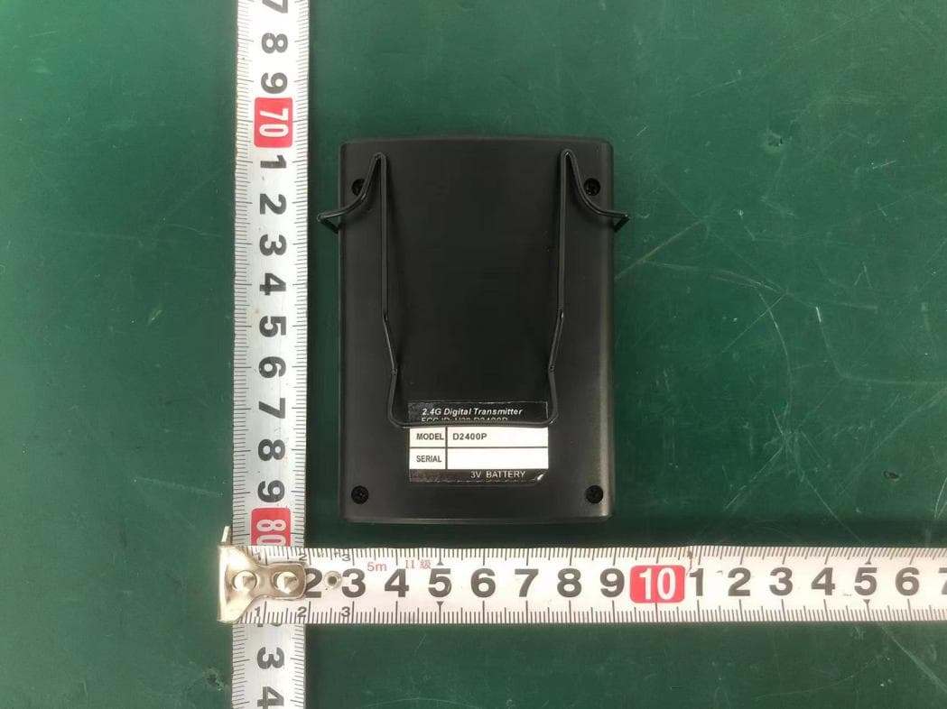
Click to zoom
Application Details
- Equipment Class
- DTS - Digital Transmission System
- Date of Grant
- Nov 26, 2025
- Application Purpose
- Original Equipment
- Equipment Note
- 2.4G Digital Transmitter
- Frequency Range
- 2402.00000000 - 2479.00000000
- Country
- Samoa
Documents & Files
Document Text
Text extracted from the exhibit documents filed with the FCC. Open a document above to read the original.
Users Manual
RF + - A B CH 0 AF 25 AF OUT POWER 2.4G Digital Wireless Microphone System INDEX IMPORTANT SAFETY INSTRUCTIONS INTRODUCTION CONTROL ELEMENTS TECHNICAL SPECIFICATIONS 1 3 4 8 ........................................................................................ ................................................................ .................................................................................. ........................................................................ CAUTIONRisk of fire or explosion if the battery is replaced by an incorrect type ATTENTION : Risque d'incendie ou d'explosion si la batterie est remplacée par un type incorrect WARNING: Remove batteries if exhausted or if they will not be used again for a long period. - The incorrect use of batteries can cause electrolyte leakage and will corrode the compartment or cause the batteries to burst, therefore: - Do not mis battery types, e.g. alkaline with zinc carbonate. - When inserting new batteries, replace all batteries at the same time. Service Instructions • Refer all servicing to authorized service personnel. Servicing is required when the apparatus has been damaged in any way, such as power-supply cord or plug is damaged, liquid has been spilled or objects have fallen into the apparatus, the apparatus has been exposed to rain or moisture, does not operaten normally, or has been dropped. • Disconnect power cord before servicing. • Replace critical components only with factory parts or recommended equivalents. • For AC line powered units: Before returning repaired unit to user, use an ohmmeter to measure from both AC plug blades to all exposed metal parts. The resistance should be more than 2,000,000 ohms. ATTENTION: RISQUE DE CHOC ÉLECTRIQUE NE PAS OUVRIR. WARNING: TO REDUCE THE RISK OF FIRE OR ELECTRIC SHOCK DO NOT EXPOSE THIS EQUIPMENT TO RAIN OR MOISTURE AVERTISSEMENT: NE PAS EXPOSER CE MATERIEL À LA PLUIE OU L’HUMIDITÉ AFIN DE RÉDUIRE LE RISQUE D’INFLAMMATION OU DE CHOC ÉLECTRIQUE RISK OF ELECTRIC SHOCK DO NOT OPEN CAUTION Warning! This symbol indicates a hot surface. Certain parts of the housing can become hot during operation. After use, wait for a cool-down period of at least 10 minutes before handling or transporting the device. Warning! This device is designed for use below 2000 metres in altitude. Warning! This product is not intended for use in tropical climates. 1. Read and keep these instructions. Heed all warnings and follow all instructions. 2. Warning (if applicable): Please refer to any important information (e.g., electrical, safety, etc.) printed on the exterior bottom enclosure or rear panel before instaling or operating the product. 3. Clean only with dry cloth. 4. Water and Moisture (if applicable): Do not use this apparatus near water. The apparatus shall not be exposed to dripping or splashing and that no objects filled with liquids, such as vases, shall be placed on the apparatus. Electrical equipment should NEVER be kept or stored in damp environments. 5. (lf applicable) Do not block any ventilation openings. install in accordance with the manufacturer's instructions. Do not install this equipment in a confined or "boxed-in" space such as a bookcase or similar unit, and maintain good ventilation conditions. The ventilation should not be impeded by covering the ventilation openings with items such as newspaper, tablecloths, curtains. etc. 6. Do not install near any heat sources such as radiators, heat registers, stoves, or other apparatus (including amplifiers) that produce heat. Do not place exposed flame sources such as lighted candles on the apparatus. 7. (lf applicable) This product should be connected to a power supply only of the type described in these operating instructions, or as marked on the unit. 8. (if applicable) Be careful not to damage the power cord. When moving or not using the appliance, secure the power cord (e.g., wrap it with a cable tie). Before using it again, make sure the power cord has not been damaged.If the power cord has been damaged at al, bring the unit and cord to a qualified service technician for repair or replacement as specified by the manufacturer. - 1 - 9. Unplug this apparatus during lightning storms or when unused for long periods of time. 10. Only use attachment/accessories specified by the manufacturer. 11. (lf applicable) Use only the cart, stand, tripod, bracket or table specified by the manufacturer, or sold with the apparatus. When a cart is used, use caution when moving the cart/apparatus combination to avoid injury from tip-over. 12. Internal/External Voltage Selectors (if applicable): Interal or external voltage selector switches, if any, should only be reset and re-equipped with a proper plug for altemative voltage by a qualified service technician. Do not attempt to alter this yourself. 13. Caution (if applicable): Danger of explosion if battery is incorrectly replaced. Replace only with the same or equivalent type. Batteries (a battery pack or an installed battery) shall not be exposed to excessive heat such as sunshine,fire,etc. 14. (lf applicable) Do not defeat the safety purpose of the polarized or grounding-type plug. 15. Protective earthing terminal (if applicable): The apparatus should be connected to a mains socket outlet with a protective earthing connection. • Denmark (Danmark): Apparatets stikprop skal tilsluttes en stikkontakt med jord, som giverforbindelse til stikproppens jord. • Finland (Suomi): Laite on liitettävä suojakoskettimilla varustettuun pistorasiaan. • Norway (Norge): Apparatet må tilkoples jordet stikkontakt. • Sweden (Sverige): Apparaten skall anslutas till jordat uttag. 16. For Class ll apparatus only: This symbol means the equipment is a Class ll or double-insulated electrical appliance. lt has been designed in such a way that it does not require a safety connection to electricalearth. When servicing use only identical replacement parts installed by an instructed person or with theuse of ready- made leads …
Text truncated - open the document above for the full version.
External Photos
External Photos M/N: D2400P External Photos M/N: D2400P External Photos M/N: D2400P External Photos M/N: D2400P
ID Label/Location Info
Label Location
ID Label/Location Info
D2400P_V1.1D2400P_V1.1 -29.7x17.7mm-29.7x17.7mm D2400PD2400P 2025.08.12 D2400P 2.4G Digital Transmitter MODEL +0.2mm -0.3mm +0.2mm -0.3mm +0.2mm -0.3mm +0.2mm -0.3mm NE37483NE37483 H38D2400P
Internal Photos
Internal Photos M/N: D2400P Internal Photos M/N: D2400P Internal Photos M/N: D2400P Antenna
RF Exposure Info
Page 1 of 3 Report No. ESTE-R2509098 FCC RF EXPOSURE REPORT SEIKAKU TECHNICAL GROUP LIMITED 2.4G Digital Transmitter Model Number: D2400P FCC ID: H38D2400P Applicant: SEIKAKU TECHNICAL GROUP LIMITED Address: Offshore Chambers, P.O.Box 217 Apia, Samoa Prepared By: EST Technology Co., Ltd. Chilingxiang, Qishantou, Santun, Houjie, Dongguan, Guangdong, China Tel: 86-769-83081888-808 Report Number: ESTE-R2509098 Date of Test: Aug. 14, 2025 ~ Sep. 04, 2025 Date of Report: Sep. 11, 2025 Page 2 of 3 Report No. ESTE-R2509098 1. Applicable Standards FCC Part 2(Section 2.1093) FCC KDB 447498 D04 Interim General RF Exposure Guidance v01 2. Exposure Evaluation of Portable or Mobile Devices Human exposure to RF emissions from portable devices (47 CFR §2.1093), as defined by the FCC, must be evaluated with respect to the FCC-adopted limits for SAR. Evaluation of mobile devices, as defined by the FCC, may also be performed with respect to SAR limits, but in such cases it is usually simpler and more cost-effective to evaluate compliance with respect to field strength or power density limits. For certain devices that are designed to be used in both mobile and portable configurations similar to those described in 47 CFR §2.1091(d)(4), such as certain desktop phones and wireless modem modules, compliance for mobile configurations is also satisfied when the same device is evaluated for SAR compliance in portable configurations. The test exclusions are applicable only when the minimum test separation distance is ≤ 50 mm and for transmission frequencies between 300 MHz and 6 GHz. When the minimum test separation distance is < 5 mm, a distance of 5 mm is applied to determine SAR test exclusion. Page 3 of 3 Report No. ESTE-R2509098 3. Evaluation Results Mode Frequency (MHz) Peak output Power (dBm) Antenna Gain (dBi) effective radiated power (dBm) Target power (dBm) Max. Target power (mW) SAR Test Exemption Limit (mW) GFSK 2402 1.90 2.63 2.38 2±1 1.995 2.72 2442 3.46 2.63 3.94 3±1 2.512 2.72 2479 3.28 2.63 3.76 3±1 2.512 2.72 Note: 1. Limited=3060*(0.5/20)^x, x=-log(60/(3060*√f)). 2. We choose f=2.479GHz (Highest frequency operate at wireless) to calculate MPE limit as higher frequency will have lower MPE limits. 3. SAR Test Exclusion Thresholds is 2.72mW for separation distance 5mm. Therefore, SAR test is not required. End of Test Report
Test Report
Summary ITEMANT SPEC Model Name2.4G ANT P MAX.Gain 2.63 dBi PolarizationHorizontal and Vertical Azimuth Beam patternomni-directional Impedance50 Ohm Antenna Length43.36 mm Manufacture Dongguan Jingheng Electron Co.,Ltd. Inverted F Antenna Sperification frequency 频率(MHz) gain 增益(dBi) efficiency 效率(dB) efficiency 效率(%) 2400.001.99-2.9051.25 2410.002.36-2.9250.99 2420.002.05-3.0749.32 2430.002.00-2.9950.21 2440.002.18-2.8751.62 2450.002.36-2.9650.59 2460.002.63-2.9550.69 2470.002.58-3.0150.04 2480.002.48-2.9450.86 2490.002.04-3.2547.28 2500.002.05-3.1548.42 Gain&Efficiency&PhaseCenter 增益、效率和相位中心
Test Report
Page 1 of 18 Report No.ESTE-R2509097 Appendix A: DTS Bandwidth Test Result TestMode Antenna Frequency[MHz] DTS BW [MHz] FL[MHz] FH[MHz] Limit[MHz] Verdict GFSK Ant1 2402 0.513 2401.637 2402.150 0.5 PASS GFSK Ant1 2442 0.525 2441.622 2442.147 0.5 PASS GFSK Ant1 2479 0.522 2478.625 2479.147 0.5 PASS Page 2 of 18 Report No.ESTE-R2509097 Test Graphs GFSK-Ant1-2402-PASS GFSK-Ant1-2442-PASS GFSK-Ant1-2479-PASS Page 3 of 18 Report No.ESTE-R2509097 Page 4 of 18 Report No.ESTE-R2509097 Appendix B: Maximum conducted output power Test Result Peak TestMode Antenna Frequency[MHz] Conducted Peak Powert[dBm] Conducted Limit[dBm] Verdict GFSK Ant1 2402 1.90 ≤30 PASS GFSK Ant1 2442 3.46 ≤30 PASS GFSK Ant1 2479 3.28 ≤30 PASS Test Graphs Peak GFSK-Ant1-2402-PASS GFSK-Ant1-2442-PASS Page 5 of 18 Report No.ESTE-R2509097 GFSK-Ant1-2479-PASS Page 6 of 18 Report No.ESTE-R2509097 Appendix C: Maximum power spectral density Test Result TestMode Antenna Frequency[MHz] Result[dBm/3kHz] Limit[dBm/3kHz] Verdict GFSK Ant1 2402 -9.88 ≤8.00 PASS GFSK Ant1 2442 -8.55 ≤8.00 PASS GFSK Ant1 2479 -8.52 ≤8.00 PASS Page 7 of 18 Report No.ESTE-R2509097 Test Graphs GFSK-Ant1-2402-PASS GFSK-Ant1-2442-PASS GFSK-Ant1-2479-PASS Page 8 of 18 Report No.ESTE-R2509097 Page 9 of 18 Report No.ESTE-R2509097 Appendix D: Reference level measurement Test Result TestMode Antenna Freq(MHz) Max.Point[MHz] Result[dBm] GFSK Ant1 2402 2401.95 0.93 GFSK Ant1 2442 2441.93 2.45 GFSK Ant1 2479 2478.88 2.48 Page 10 of 18 Report No.ESTE-R2509097 Test Graphs GFSK-Ant1-2402-PASS GFSK-Ant1-2442-PASS GFSK-Ant1-2479-PASS Page 11 of 18 Report No.ESTE-R2509097 Page 12 of 18 Report No.ESTE-R2509097 Appendix E: Band edge measurements Test Result TestMode Antenna ChName Frequency [MHz] RefLevel[dBm] Result[dBm] Limit[dBm] Verdict GFSK Ant1 Low 2402 0.93 -40.19 ≤-19.07 PASS GFSK Ant1 High 2479 2.48 -39.43 ≤-17.52 PASS Page 13 of 18 Report No.ESTE-R2509097 Test Graphs GFSK-Ant1-2402-PASS GFSK-Ant1-2479-PASS Page 14 of 18 Report No.ESTE-R2509097 Appendix F: Conducted Spurious Emission Test Result TestMode Antenna Frequency[MHz] FreqRange [MHz] RefLevel [dBm] Result[dBm] Limit[dBm] Verdict GFSK Ant1 2402 30~26500 0.93 -42.01 ≤-19.07 PASS GFSK Ant1 2442 30~26500 2.45 -42.05 ≤-17.55 PASS GFSK Ant1 2479 30~26500 2.48 -41.81 ≤-17.52 PASS Page 15 of 18 Report No.ESTE-R2509097 Test Graphs GFSK-Ant1-2402-30~26500-PASS GFSK-Ant1-2442-30~26500-PASS GFSK-Ant1-2479-30~26500-PASS Page 16 of 18 Report No.ESTE-R2509097 Page 17 of 18 Report No.ESTE-R2509097 Appendix G: Duty Cycle Test Result TestMode Antenna Frequency[MHz] ON Time [ms] Period [ms] Duty Cycle [%] Duty Cycle Factor[dB] GFSK Ant1 2442 20.00 20.00 100.00 0.00 Page 18 of 18 Report No.ESTE-R2509097 Test Graphs NTNV-GFSK-Ant1-2442
Test Report
Page 1 of 42 Report No.ESTE-R2509097 FCC PART 15C TEST REPORT FOR CERTIFICATION On Behalf of SEIKAKU TECHNICAL GROUP LIMITED 2.4G Digital Transmitter Model Number: D2400P FCC ID: H38D2400P Applicant: SEIKAKU TECHNICAL GROUP LIMITED Address: Offshore Chambers, P.O.Box 217 Apia, Samoa Prepared By: EST Technology Co., Ltd. Chilingxiang, Qishantou, Santun, Houjie, Dongguan, Guangdong, China Tel: 86-769-83081888-808 Report Number: ESTE-R2509097 Date of Test: Aug. 14, 2025 ~ Sep. 04, 2025 Date of Report: Sep. 11, 2025 Page 2 of 42 Report No.ESTE-R2509097 TABLE OF CONTENTS Description Page TEST REPORT VERIFICATION .......................................................................................................... 3 1. GENERAL INFORMATION ................................................................................................................... 5 1.1. Description of Device (EUT) ............................................................................................................ 5 1.2. Antenna Information ......................................................................................................................... 5 1.3. Information of RF Cable ................................................................................................................... 5 2. SUMMARY OF TEST ........................................................................................................................... 6 2.1. Summary of test result ..................................................................................................................... 6 2.2. Test Facilities ..................................................................................................................................... 7 2.3. Measurement uncertainty ................................................................................................................ 8 2.4. Assistant equipment used for test .................................................................................................. 8 2.5. Block Diagram ................................................................................................................................... 8 2.6. Test Mode .......................................................................................................................................... 9 2.7. Power Setting of Test Software ...................................................................................................... 9 2.8. Duty Cycle .......................................................................................................................................... 9 2.9. Channel List ..................................................................................................................................... 10 2.10. Test Equipment List ...................................................................................................................... 11 3. 6DB BANDWIDTH ............................................................................................................................ 13 3.1. Limit ................................................................................................................................................... 13 3.2. Test Setup ........................................................................................................................................ 13 3.3. Spectrum Analyzer Setting ............................................................................................................ 13 3.4. Test Procedure ................................................................................................................................ 13 3.5. Test Result ....................................................................................................................................... 13 4. MAXIMUM PEAK OUTPUT POWER .................................................................................................. 14 4.1. Limit ................................................................................................................................................... 14 4.2. Test Setup ........................................................................................................................................ 14 4.3. Spectrum Analyzer Setting ............................................................................................................ 14 4.4. Test Procedure ................................................................................................................................ 14 4.5. Test Result ....................................................................................................................................... 14 5. POWER SPECTRAL DENSITY .......................................................................................................... 15 5.1. Limit ................................................................................................................................................... 15 5.2. Test Setup ........................................................................................................................................ 15 5.3. Spectrum Analyzer Setting ............................................................................................................ 15 5.4. Test Procedure ................................................................................................................................ 15 5.5. Test Result ....................................................................................................................................... 15 6. CONDUCTED BAND EDGE .............................................................................................................. 16 6.1. Limit ................................................................................................................................................... 16 6.2. Test Setup .................…
Text truncated - open the document above for the full version.
Test Setup Photos
Radiated Test (30-1000 MHz) Radiated Test (Above 1GHz)
Contact Information
Applicant
Henry lee(R&D)
[email protected]Fax: 86-769-83371915
Test Firm
EST Technology Co., Ltd.Iceman Hu
Technical Specifications
| # | Rule Parts | Frequency Range | Power Output |
|---|---|---|---|
| 1 | 15C | 2.40 GHz - 2.48 GHz | 2.22 mW |
Other Applications from SEIKAKU TECHNICAL GROUP LIMITED

H38-RABT-ATS2819
May 09, 2023Bluetooth Module
Equipment Class
DTS - Digital Transmission System
H38WS-5
Oct 10, 2020PORTABLE SOUND SYSTEM WITH BLUETOOTH
Equipment Class
DSS - Part 15 Spread Spectrum Transmitter
H38WS-6
Sep 22, 2020PORTABLE SOUND SYSTEM WITH BLUETOOTH
Equipment Class
DSS - Part 15 Spread Spectrum Transmitter
H38WT-X
May 05, 2020PLL UHF Creative pen-shape microphone System
Equipment Class
DWM - Part 15 Wireless MicrophoneH38WNA-2
Aug 01, 2015WIRELESS NETWORK PLAYER
Equipment Class
DTS - Digital Transmission System