H3YHP6777Wireless Headphone
ADY Technologies Limited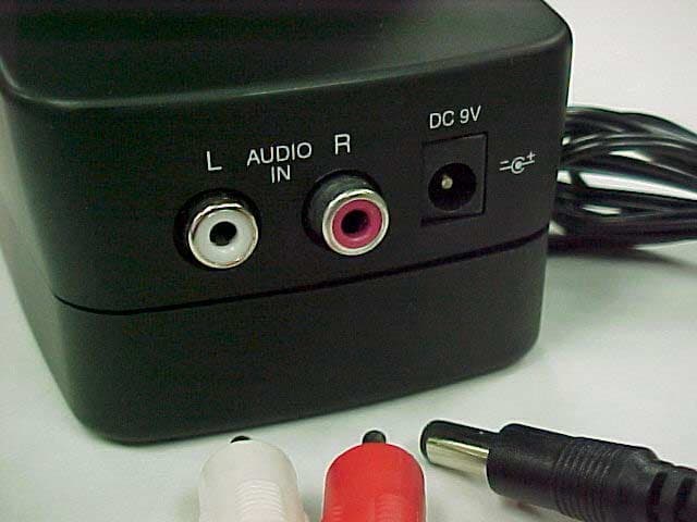
Click to zoom
Application Details
- Equipment Class
- DXX - Part 15 Low Power Communication Device Transmitter
- Date of Grant
- Sep 26, 2002
- Application Purpose
- Original Equipment
- Date of Application
- Sep 26, 2002
- Equipment Note
- Wireless Headphone
- Frequency Range
- 903.00000000 - 904.00000000
- Company
- ADY Technologies Limited
- Country
- Hong Kong
Documents & Files
Document Text
Text extracted from the exhibit documents filed with the FCC. Open a document above to read the original.
Users Manual
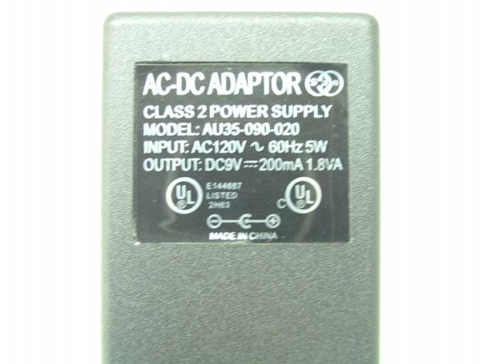
TX0001 - Installation & Operation Instruction PLEASE READ YOUR MANUAL THOROUGHLY Contents - Wireless Headphones, Transmitter, Dual RCA Cable and ‘Y’ Adapter Cable OPERATING CONTROLS (Transmitter) 1. Power Indicator Light - Lights to indicate that power is being supplied to the TX/0001 transmitter. 2. Power ON/OFF (Channel 1/2) Switch - This switch turns the power on and chooses which of the two channels to transmit. Note: Transmitter and headphones must be set to same channel. 3. Battery Compartment - located on bottom side of transmitter. (Requires 4 ‘AA’ batteries or AC adapter both not included) 4. Left/Right audio Input Jacks - Connect the transmitter to the audio jacks of sound source (TV or other audio components). Insert Dual RCA Cable here. 5. Power Connection Input Jack - AC-DC adapter (Optional-Not Included) plugs into transmitter at this location. OPERATING CONTROLS (Wireless Headphones) 6. Power ON/OFF Switch - Place this switch in the ON position to use wireless headphones and in OFF position when the headphones are not in use. 7. Power Indicator Light - Lights to indicate that power is being supplied to the TX/0001 wireless headphones. 8. Stereo indicator Light - This lights up to indicate that the wireless headphones are emitting stereo sound. 9. Channel 1/2 Switch - This switch chooses what channel your headphones will receive from the transmitter. Note: Transmitter and wireless headphones must be set to same channel. 10. Volume Level Control Wheel - Use this switch to adjust the volume of your wireless headphones. 11. Battery Compartment - Headphone requires 2 'AA’ batteries (not included). TRANSMITTER HOOKUP A. (Option 1) Place 4 ‘AA' batteries in the bottom of the transmitter. (Also required - 2 ‘AA’ batteries in headset). (Option 2) Connect AC adapter to transmitter and wall outlet (also required - 2 ‘AA’ batteries in the headset). B. Connect Transmitter to Audio source (see Fig 1.3) 1. Connect one end of the Dual RCA Cable to your audio source’s left and right audio output jacks. Note: If there are no fixed-level audio outputs on the audio source, connect the cable to variable-level (HI-FI) audio outputs, or refer to Section C for “Y” adapter connection instructions. 2. Connect the other end of the Dual RCA Cable to the Left/Right Audio Input Jacks on the transmitter. WARNING : DO NOT connect the Dual RCA Cable to the speaker terminals of the TV or Audio Source. This may damage your transmitter and/or your audio source. C. If no Audio Output Jacks are available - Connect to headphone Jack using “Y” Adapter Cable (included) and Dual RCA patch cord (included) (see Fig 1.4) 1. Connect the color coded, left (white) and right (red) ends of the Dual RCA Cable to the “Y” Adapter Cable. 2. Connect the 1/8” headphone plug on the “Y” Adapter Cable to the headphone input jack located on your audio source. If your audio source requires a headphone plug, you will require a Headphone Jack Adapter Plug (not included) then insert into your source’s headphone input jack. 3. Connect the other end of the DUAL RCA Cable to the Left/Right Audio Input Jacks on the rear of transmitter OPERATION A. Transmitter Operation and Adjustment 1. Turn on power to your audio source (TV, Portable Device etc.) to which the transmitter is connected. NOTE: If transmitter is connected to the audio variable level outputs, adjust the volume of the source (TV, etc) to desired listening level. If transmitter is connected to fixed-level outputs, no volume adjustment is needed. 2. Adjust the Power ON/OFF (channel) switch to channel 1 or 2 (same as channel selected on the headphones). B. Headphone Operation and Adjustments 1. Insure that you have inserted 2 ‘AA’ batteries in the headphone battery compartment. 2. Turn ON/OFF switch to the On position. Power indicator on headphones should light up. 3. Adjust Channel selector to match channel selected on the transmitter. Stand 10-15 ft. away from the transmitter. 4. Place the headphones over your ears and adjust the volume to your desired listening level. Note: If signal interference occurs, adjust the channel selection on both the headphone and transmitter. To Preserve Your Batteries, When Not In Use Turn The Power Switch To The OFF Position On The Headphones And Transmitter TRANSMITTER SPECIFICATIONS FOR OPTIONAL AC ADAPTER (NOT INCLUDED): Input: 120 V AC 60 Hz 5W Output: 9 V DC 200mA Polarity: Positive Tip Coaxial Plug: O.D. 4.75mm, I.D. 1.7mm CARE • Keep the transmitter and wireless headphones dry. • Do Not Drop. Handle the wireless headphones and transmitter carefully. • Do Not use or store the wireless headphones and transmitter in extreme temperatures. • Remove batteries when not in use. • Do Not modify or tamper with the wireless headphone and/or transmitter’s internal components. Doing so will void the wireless headphone’s and/or transmitter’s warranty FCC Compliance Statement (Part 15.19) This device complies with Part 15 of the FCC Rules. Operation is subject to the following two conditions. 1. This device may not cause harmful interference, and 2. This device must accept any interference received, including interference that may cause undesired operation. Warning (Part 15. 21) Changes or modifications not expressly approved by the party responsible for compliance could void the user’s authority to operate the equipment. Industry Canada The term “IC” before the certification/registration number only signifies that the Industry Canada technical specifications were met. 1. 3. 2. 4. 5. 6. 7. 8. 9. 10. 11. Fig 1.3 Fig 1.4
External Photos
ADY Technologies, Ltd. Wireless Transmitter for Audio Headset Reception FCC ID#: H3Y-HP6777 Photo One Wireless Transmitter with I/O Cables and Power Cable ADY Technologies, Ltd. Wireless Transmitter for Audio Headset Reception FCC ID#: H3Y-HP6777 Photo Two Wireless Transmitter – Front View ADY Technologies, Ltd. Wireless Transmitter for Audio Headset Reception FCC ID#: H3Y-HP6777 Photo Three Wireless Transmitter – Side View showing Power and Channel Selection ADY Technologies, Ltd. Wireless Transmitter for Audio Headset Reception FCC ID#: H3Y-HP6777 Photo Four Wireless Transmitter – Interface Cables ADY Technologies, Ltd. Wireless Transmitter for Audio Headset Reception FCC ID#: H3Y-HP6777 Photo Five Wireless Transmitter – Interface Cables Close up of I/O Connections with Cables ADY Technologies, Ltd. Wireless Transmitter for Audio Headset Reception FCC ID#: H3Y-HP6777 Photo Six Wireless Transmitter – Interface Cables Close up of I/O Connections without Cables
ID Label/Location Info
FCC Label for Photos: ADY Model No.: HP6777 Canada ID: 3518A-HP6777 FCC ID: H3Y-HP6777 This device complies with Part 15 of the FCC Rules. Operation is subject to the following two conditions: 1.) this device may not cause harmful interference, and 2.) this device must accept any interference received, including interference that may cause undesired operation. FCC label material Face Stock: Material : Clear Polyester Thickness : .025+/-.002mm Specific Weight: 33.2 gram/M^2 Color : Clear Glue: Material Acrylic compound Glue Thickness ; .02+/-.002 mm Volume of the glue applied: 28 +/-.002 gram/mm^2 Adhesion Force: 8+/-.56 kgs/25mm^2 Working Temp: -10 C to 105 C
ID Label/Location Info
ADY Technologies, Ltd. Wireless Transmitter for Audio Headset Reception FCC ID#: H3Y-HP6777 Photo Twenty Wireless Transmitter – Battery Compartment Door with FCC ID Label open to expose FCC ID Label inside the Battery Compartment. This additional label is added to comply with Title 47 – Telecommunication Rules. FCC Label Material Face Stock: Material : Clear Polyester Thickness : .025+/-.002mm Specific Weight: 33.2 gram/M^2 Color : Clear Glue: Material Acrylic compound Glue Thickness ; .02+/-.002 mm Volume of the glue applied: 28 +/-.002 gram/mm^2 Adhesion Force: 8+/-.56 kgs/25mm^2 Working Temp: -10 C to 105 C
Internal Photos
ADY Technologies, Ltd. Wireless Transmitter for Audio Headset Reception FCC ID#: H3Y-HP6777 Photo Ten Wireless Transmitter – Open for Inspection ADY Technologies, Ltd. Wireless Transmitter for Audio Headset Reception FCC ID#: H3Y-HP6777 Photo Eleven Wireless Transmitter – PCB Non Component Side ADY Technologies, Ltd. Wireless Transmitter for Audio Headset Reception FCC ID#: H3Y-HP6777 Photo Twelve Wireless Transmitter – PCB Component Side with RF Section Shielded ADY Technologies, Ltd. Wireless Transmitter for Audio Headset Reception FCC ID#: H3Y-HP6777 Photo Thirteen Wireless Transmitter – RF Section Close Up ADY Technologies, Ltd. Wireless Transmitter for Audio Headset Reception FCC ID#: H3Y-HP6777 Photo Fourteen Wireless Transmitter – RF Antenna
Test Report
L.S. Compliance, Inc. W66 N220 Commerce Court Cedarburg, WI 53012 262-375-4400 Fax: 262-375-4248 Compliance Testing of : HP 6777 Wireless Headphone Prepared For : Mr. Narain Daryanani ADY Technologies, Ltd. Room 1302, Perfect Commercial Building 20 Austin Avenue TSIM SHA TSUI Kowloon, Hong Kong Test Report Number : 302343 TX Revision 1 Test Dates : September 10 th , 11 th , 16 th and 17 th , 2002 All results of this report relate only to the items that were tested. This report may not be reproduced, except in full, without written approval of L.S. Compliance, Inc. ________________________________________________________________________ FCC I.D. #H3Y-HP6777 Page 2 of 24 L.S. Compliance, Inc. Prepared For: ADY Technologies, Ltd. Test Report: 302343 TX Revision 1 Table of Contents Section Description Type of Test Page # Index 2 1 L. S. Compliance in Review 3 2 A2LA Certificate of Accreditation 4 3 A2LA Scope of Accreditation 5 4 Validation Letter- U.S. Competent Body for EMC Directive 89/336/EEC 6 5 Signature Page 7 6 Product General Information 8 7 Introduction 8 8 Purpose 8 9 Product Description 9 10 Test Requirements 9 11 Summary of Test Report 9 12 Radiated Emission Test 10-17 13 Conducted Emission Test 18-21 Appendices A Calculations 22 B Test Equipment List 23 ________________________________________________________________________ FCC I.D. #H3Y-HP6777 Page 3 of 24 L.S. Compliance, Inc. Prepared For: ADY Technologies, Ltd. Test Report: 302343 TX Revision 1 1. L.S. Compliance in Review L. S. Compliance, Inc. is located in Cedarburg, Wisconsin ñ United States. We may be contacted by: Mail: L. S. Compliance, Inc. W66 N220 Commerce Court Cedarburg, Wisconsin 53102 Phone: 262-375-4400 Fax: 262-375-4248 E-Mail: [email protected] As an EMC testing laboratory, our accreditation and assessments are recognized through the following: A2LA ñ American Association for Laboratory Accreditation Accreditation based on ISO/IEC 17025: 2001 With electrical (EMC) Scope of Accreditation A2LA Certificate Number: 1255.01 U.S. Conformity Assessment Body (CAB) Validation Validated by the European Commission as a U.S. conformity assessment Body operating under the U.S./EU, Mutual Recognition Agreement (MRA) operating under the European Union EMC Directive 89/336/EEC, Article 10.2 Date of Validation: January 16, 2001 Federal Communications Commission (FCC) ñ USA Listing of 3 Meter Semi-Anechoic Chamber based on 47CFR 2.948 FCC Registration Number: 90756 Listing of 3 and 10 Meter OATS based on 47CFR 2.948 FCC Registration Number: 90757 Industry Canada On-file, 3 Meter Semi-Anechoic Chamber based on 47CFR 2.948 File Number: IC 3088 On-file 3 and 10 meter OATS based on RSS-210 File Number: IC 3088-A ________________________________________________________________________ FCC I.D. #H3Y-HP6777 Page 4 of 24 L.S. Compliance, Inc. Prepared For: ADY Technologies, Ltd. Test Report: 302343 TX Revision 1 2. A2LA Certificate of Accreditation ________________________________________________________________________ FCC I.D. #H3Y-HP6777 Page 5 of 24 L.S. Compliance, Inc. Prepared For: ADY Technologies, Ltd. Test Report: 302343 TX Revision 1 3. A2LA Scope of Accreditation ________________________________________________________________________ FCC I.D. #H3Y-HP6777 Page 6 of 24 L.S. Compliance, Inc. Prepared For: ADY Technologies, Ltd. Test Report: 302343 TX Revision 1 4. Validation Letter ñ U.S. Competent Body for EMC Directive 89/336/EEC ________________________________________________________________________ FCC I.D. #H3Y-HP6777 Page 7 of 24 L.S. Compliance, Inc. Prepared For: ADY Technologies, Ltd. Test Report: 302343 TX Revision 1 5. Signature Page September 19, 2002 Prepared By: ________________________________________________________ Teresa A. White, Document Coordinator Date September 19, 2002 Tested By: ________________________________________________________ Thomas T. Smith, EMC Engineer Date September 19, 2002 Approved By: ________________________________________________________ Kenneth L. Boston, EMC Lab Manager Date PE #31926 Licensed Professional Engineer Registered in the State of Wisconsin, United States ________________________________________________________________________ FCC I.D. #H3Y-HP6777 Page 8 of 24 L.S. Compliance, Inc. Prepared For: ADY Technologies, Ltd. Test Report: 302343 TX Revision 1 6. Product and General Information ADY Technologies, Ltd. HP 6777 Engineering Unit Dual Frequency; 903.0 MHz and 904.0 MHz Manufacturer: Model Number: Serial Number: Frequency Range: Test Voltage: 120VAC/60Hz Environmental Conditions in the Test Lab : Temperature: 20-25◦ C Atmospheric Pressure: 86kPa-106kPa Humidity: 30-60% 7. Introduction On September 10 th , 11 th , 16 th and 17 th , 2002 a series of Radiated Emissions tests were performed on the ADY Model #HP 6777 Transmitter. This product is powered by 120VAC/60Hz. These tests were performed using the test procedure outlined in ANSI C63.4, 2001 for intentional radiators, and in accordance with the limits set forth in FCC Part 15.249, for a manually operated transmitter. 8. Purpose The above-mentioned tests were performed in order to determine the compliance of the equipment under test (EUT), with limits contained in various provisions of Title 47CFR, FCC Part 15, including: 15.205, 15.207, 15.209 and 15.249. All radiated emission tests were performed to measure the emissions in the frequency bands described in Section 12i of this report, and to determine whether said emissions are below the limits established by the sections above. These tests were performed in accordance with the procedures described in the American National Standard for methods of measurements of Radio-Noise Emissions from Low-Voltage Electrical and Electronic Equipment in the Range of 9 kHz to 40 GHz (ANSI C63.4, 2001). Also used as a reference, for the EMI Receiver specification, is the International Special Committee on Radio Interference ñ CISPR 16-1, 1999. ________________________________________…
Text truncated - open the document above for the full version.
Test Setup Photos
________________________________________________________________________ FCC I.D. #H3Y-HP6777 Page 12 of 24 L.S. Compliance, Inc. Prepared For: ADY Technologies, Ltd. Test Report: 302343 TX Revision 1 12f. Photo of Setup for Radiated Emissions Test In the 3 Meter Semi-Anechoic Chamber
Contact Information
Applicant
Kendy Ip(Engineering Manager)
852 2722-1139Fax: 852 2723-0727
Test Firm
LS Research, LLCRyan Urness
Technical Specifications
| # | Rule Parts | Frequency Range | Power Output |
|---|---|---|---|
| 1 | 15C | 903 MHz - 904 MHz | - |
Other Applications from ADY Technologies Limited
H3YD3T6777
Oct 18, 2004900MHz Wireless Audio System
Equipment Class
DXX - Part 15 Low Power Communication Device Transmitter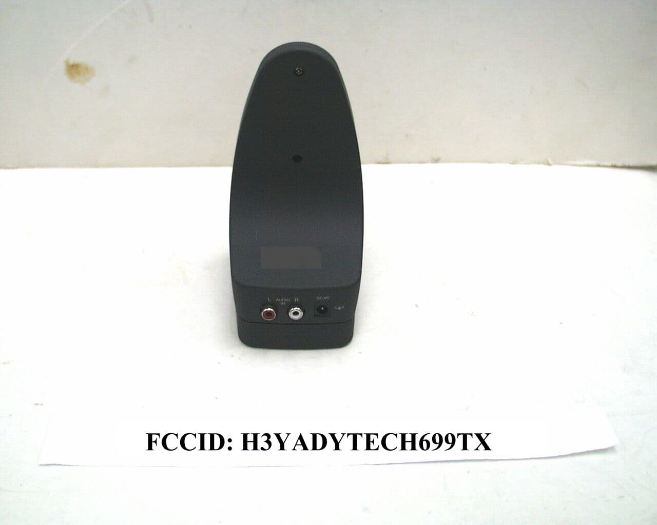
H3YADYTECH699TX
Mar 13, 2000Wireless Transmitter
Equipment Class
DXX - Part 15 Low Power Communication Device Transmitter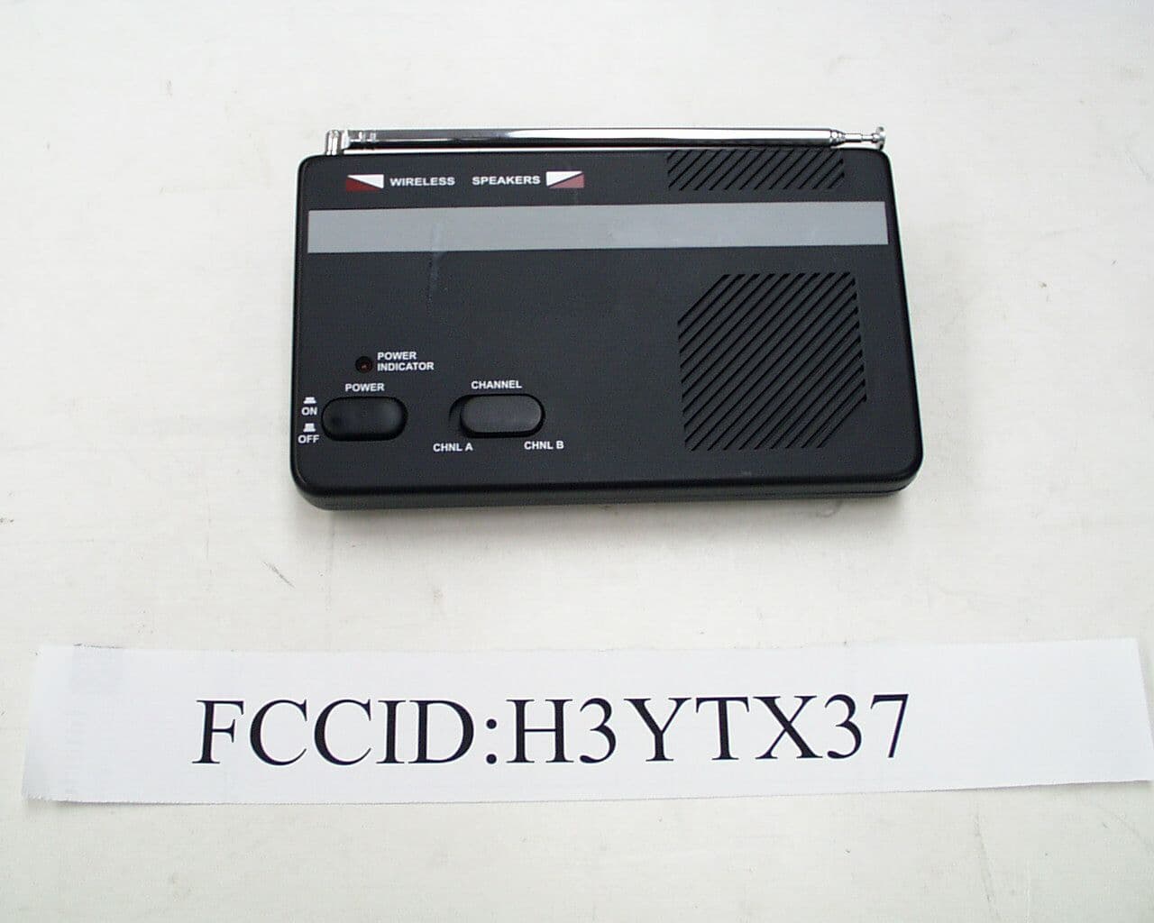
H3YTX37
Feb 07, 2000Wirless Speaker TX
Equipment Class
DXX - Part 15 Low Power Communication Device Transmitter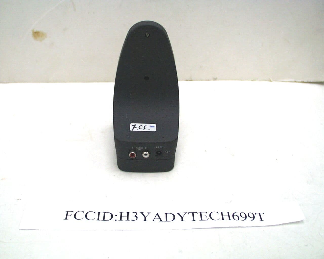
H3YADYTECH699T
Jan 05, 2000900MHZ Wireless Speaker System ( Transmitter)
Equipment Class
DXX - Part 15 Low Power Communication Device TransmitterH3YADYTECHWS-9R
Nov 30, 1997Wireless Speaker System Receiver
Equipment Class
CYY - Communications Receiver used w/Pt 15 Transmitter