H47-PHAZORAnti-Shoplifting Field Disturbance Transmitter
Ketec Inc
Click to zoom
Application Details
- Equipment Class
- FAP - Part 15 Anti-Pilferage Device
- Date of Grant
- Sep 10, 2007
- Application Purpose
- Original Equipment
- Date of Application
- Sep 10, 2007
- Equipment Note
- Anti-Shoplifting Field Disturbance Transmitter
- Frequency Range
- 7.65000000 - 8.70000000
- Company
- Ketec Inc
- Country
- United States
Documents & Files
Document Text
Text extracted from the exhibit documents filed with the FCC. Open a document above to read the original.
Users Manual
KETEC PHAZOR SYSTEM AND TAG INSTALLATION GUIDE PLEASE READ CAREFULLY KETEC INC. INSTALLATION GUIDE NO. 006 REV.0 © May 29, 2007 FCC COMPLIANCE This equipment has been tested and found to comply with the limits stated in Part 15 of the FCC Rules. These limits are designed to provide reasonable protection against harmful interference when the equipment is operated in a commercial environment. This equipment generates, uses, and can radiate radio frequency energy and, if not installed and used in accordance with the instruction manual, may cause harmful interference to radio communications. However, there is no guarantee that interference will not occur in a particular installation. Operation of this equipment in a residential area may cause harmful interference, in which case the user will be required to correct the interference. EQUIPMENT MODIFICATION Any equipment changes or modifications not expressly approved by Ketec Inc. could void the user's authority to operate this equipment under Part 15 of the FCC Rules. Unauthorized changes or modifications will also void any warranty provided by Ketec Inc. WARRANTY DISCLAIMER Ketec Inc. makes no representation or warranty with respect to the contents hereof and specifically disclaims any implied warranties of merchantability or fitness of purpose. Further, Ketec Inc. reserves the right to revise this publication or make changes to its content without obligation to notify any person or company of such revision or change. Copyright 2007 All rights reserved No part of this manual may be reproduced in any form without written permission from Ketec Inc. Installation Before installing any Ketec equipment, check all packing materials to be sure that all parts, hardware, manuals, etc., have been included. Be sure that there is sufficient room to install the system, and that there is a 120VAC outlet within 10 feet of the system. A single aisle system will usually consist of (1) antenna panel and (1) wall-mount power supply. Position the completed assembly at the area that you wish to protect, trying to keep away from any power, telephone, or computer wires. Fasten the antenna to the floor, with the appropriate hardware, through the mounting holes provided in the antenna base. Plug the power supply into an available 120 VAC wall outlet. THAT'S ALL!! Phazor Antenna Panel 120 VAC Wall-Plug In Power Supply Tagging Guide The Phazor is a hard and soft tag detection system that will respond to any tags within several feet of the antenna panel. Since the detection field extends from both sides of the panel, it is important to avoid placing any tagged merchandise within the protected area. As a general rule, tags should be at least 6 feet from all sides of the antenna panel. REMEMBER: Hard tags used with this system must be removed at the cash register using the appropriate detacher. Failure to remove any tag will result in an alarm as the customer leaves the store. Tagged Merchandise can Tagged Merchandise can be placed in this area. be placed in this area. Tagged Merchandise can Tagged Merchandise can be placed in this area. be placed in this area.
Attestation Statements
Testing the Phazor for FCC Part 15 Certification: The Phazor system uses a swept frequency transmitter that is gated on and off at a frequency of 667Hz. The sweep technique, definition, and measurement is the same as used and previously agreed upon by the FCC for similar devices manufactured by Checkpoint Systems Inc. and Ketec Inc. See included documents from Ed Gibbons and Rich Fabina of the FCC. 1.The Phazor will produce 8 pulsed emissions at 8 different frequencies. The generation and transmission of these frequencies constitutes the fundamental frequency band and will be considered as a frequency hopping swept emission. The bandwidth is considered to be the spectrum between the lowest and highest pulsed frequencies and is greater than 10%. This satisfies the swept frequency requirement of Section 15.205(d). 2.The 8 frequencies will be considered as one fundamental frequency centered at 8.175 MHz. 3.The ratio of the maximum restricted band infringed upon divided by the fundamental emission bandwidth must be less than 1% to satisfy Section 15.205. 4.The transmitter is microprocessor controlled and is not capable of stopping in any restricted band. By its’ inherent design, the transmitter is also incapable of stopping the sweep during measurements. 5.Fundamental and harmonic emissions up to 10 MHz will be measured at their true peak value according to the analyzer. To measure true peak, the analyzer is set to a frequency span of 6-10 MHz, peak detector, 300KHz Bandwidth, in the “max hold” condition. (Increasing the bandwidth beyond 300KHz does not increase the peak reading.) The peak reading of the displayed emission is then compared to the average limit of 15.223 (100uv/m @ 30m or 40dbuv/m) plus 20db. The corrected limit will be 60dbuv/m @ 30m. This is done due to the swept and pulsed nature of the transmission and in agreement with the FCC. 6.Emissions above 10 MHz will be made using CISPR quasi-peak measurements. 7.Conducted emissions remain as specified in Part 15 rules. Included are a copy of the FAX from Ed Gibbons to Checkpoint Systems, dated 8/2/96, agreeing with the above measurement method, a reprint of text for clarity, and a copy of the email from Rich Fabina to Ketec Inc. confirming the same method for a similar Ketec product. Text clarification of the Ed Gibbons Fax. Corrections made by Mr. Gibbons edited in. Dear Mr. Gibbons, Following up on our recent phone conversations, please confirm and if necessary correct our understanding of the points discussed below. Based on the details of our fax dated 7/3/96. •Our pulsed emissions will be treated as frequency hopping, where the bandwidth will be considered the spectrum contained between the lowest and highest carrier frequency we pulse. •A simple ratio of the maximum single restricted band infringed upon divided by the bandwidth of our fundamental emission must be less than 1% to satisfy section 15.205 of the rules. •For fundamental and harmonic emissions in the band 1.705 - 10 MHz, a 20db reduction from the true peak is to be compared to the limits of 100 uv/m at 30 meters. The unit is modulated as normally installed. True peak refers to the point at which the analyzer bandwidth is adjusted for maximum pulse desensitization. •For emissions outside the 1.705 - 10MHz band, CISPR quasi-peak measurements will be made with the unit modulating as normally installed. Based on the bandwidth plot, care must be given to measure multiples of the worst case emission points. Limits are specified in section 15.209. •Conducted emissions remain as specified in part 15 of the rules. A copy of the fax from Ed Gibbons to Checkpoint and the email from Rich Fabina to Ketec:
External Photos
PHAZOR Pictures: Full System with Power Supply
Internal Photos
Rear View Shield Cover Removed PCB Front View Shield Can Attached PCB Front View Shield Can Removed Front View Plastic Cover Removed Rear View Plastic Cover Removed Front View Shield Can Removed PCB Shield Can Area PCB Front Terminal Block Connections PCB Rear View Shield Cover Attached PCB Rear View Shield Cover Removed Power Supply
Test Report
Report Number 3125816BOX-007 Page 1 of 35 EMISSIONS TEST REPORT Report Number: 3125816BOX-007 Project Number: 3125816 Testing performed on the Anti-Theft Device Model: Phazor To FCC Part 15 Subpart C 15.223 For Ketec, Inc. Test Performed by: Test Authorized by: Intertek – ETL SEMKO 70 Codman Hill Road Boxborough, MA 01719 Ketec, Inc. 1256 N. Church Street, Unit A Moorestown, NJ 08057 Prepared by: Date: 08/23/2007 Nicholas Abbondante Reviewed by: Date: 08/24/07 Jeff Goulet This report is for the exclusive use of Intertek’s Client and is provided pursuant to the agreement between Intertek and its Client. Intertek’s responsibility and liability are limited to the terms and conditions of the agreement. Intertek assumes no liability to any party, other than to the Client in accordance with the agreement, for any loss, expense or damage occasioned by the use of this report. Only the Client is authorized to copy or distribute this report and then only in its entirety. Any use of the Intertek name or one of its marks for the sale or advertisement of the tested material, product or service must first be approved in writing by Intertek. The observations and test results in this report are relevant only to the sample tested. This report by itself does not imply that the material, product, or service is or has ever been under an Intertek certification program. This report must not be used to claim product endorsement by A2LA, NIST nor any other agency of the U.S. Government. Report Number 3125816BOX-007 Page 2 of 35 1.0 Job Description 1.1 Client Information This EUT has been tested at the request of: Company: Ketec, Inc. 1256 N. Church Street Unit A Moorestown, NJ 08057 Contact: Mr. Rich Frohberg Telephone: Fax: Email: 856-778-4343 856-778-8337 [email protected] 1.2 Equipment Under Test Equipment Type: Anti-Theft Device Model Number(s): Phazor Serial number(s): BOX0706200824-001 Manufacturer: Ketec, Inc. EUT receive date: 08/15/2007 EUT received condition: Prototype in Good Condition Test start date: 08/15/2007 Test end date: 08/16/2007 1.3 Test Plan Reference: Tested according to the standards listed and ANSI C63.4:2003. 1.4 Test Configuration 1.4.1 Block Diagram EUT Power Report Number 3125816BOX-007 Page 3 of 35 1.4.2. Cables: Cable Shielding Connector Length (m) Qty. Power Cable None Plastic/wire ~2.5 1 1.4.3. Support Equipment: Name: Model No.: Serial No.: None 1.5 Mode(s) of Operation: The EUT was activated from nominal 120V/60Hz power and was transmitting continuously (normal operation) during testing. The EUT is a transmitter that operates centered at 8.175 MHz, with using 8 discrete frequencies, the lowest of which is 7.65 MHz and the highest of which is 8.7 MHz. The transmitter operates in a sept frequency hopping arrangement. During testing, the highest amplitude representative frequency of the 8 was selected for test at both fundamental frequencies and at harmonics. 1.6 Floor Standing Equipment: Applicable:_X __ Not Applicable:___ Report Number 3125816BOX-007 Page 4 of 35 2.0 Test Summary TEST STANDARD RESULTS FCC Part 15 Subpart C 15.223 SUB-TEST TEST PARAMETER COMMENT Fundamental Field Strength FCC 15.223 Fundamental field strength must not exceed 60 dBuV/m peak and 40 dBuV/m average at a test distance of 30m, when measured with a 300 kHz RBW. See Appendix A for details. Average values are obtained from application of the calculated duty cycle correction factor to the fundamental field strength amplitude measured with a peak detector. Pass Radiated Emissions, <30 MHz FCC 15.209 Emissions must be below FCC 15.209 limits Pass Radiated Emissions, >30 MHz FCC 15.209 Emissions must be below FCC 15.209 limits Pass Duty Cycle FCC 15.35(c) No limit No Limit Emission Bandwidth FCC 15.205(d)(1) The ratio of the maximum restricted band infringed upon divided by the fundamental emission bandwidth must be less than 1%. Pass AC Line-Conducted Emissions FCC 15.207 Emissions must be below FCC 15.207 limits Pass REVISION SUMMARY – The following changes have been made to this Report: Date Project No. Project Handler Page(s) Item Description of Change Report Number 3125816BOX-007 Page 5 of 35 3.0 Sample Calculations The field strength is calculated by adding the Antenna Factor and Cable Factor, and subtracting the Amplifier Gain (if any) from the measured reading. The basic equation with a sample calculation is as follows: FS = RA + AF + CF - AG Where FS = Field Strength in dBμV/m RA = Receiver Amplitude (including preamplifier) in dBμV CF = Cable Attenuation Factor in dB AF = Antenna Factor in dB AG = Amplifier Gain in dB In the following table(s), the reading shown on the data table reflects the preamplifier gain. An example for the calculations in the following table is as follows. Assume a receiver reading of 52.0 dBμV is obtained. The antenna factor of 7.4 dB and cable factor of 1.6 dB is added. The amplifier gain of 29 dB is subtracted, giving a field strength of 32 dBμV/m. This value in dBμV/m was converted to its corresponding level in μV/m. RA = 52.0 dBμV AF = 7.4 dB/m CF = 1.6 dB AG = 29.0 dB FS = 32 dBμV/m Level in μV/m = [10( 32 dBμV/m)/20] = 39.8 μV/m The following is how net line-conducted readings were determined: NF = RF + LF + CF + AF Where NF = Net Reading in dBμV RF = Reading from receiver in dBμV LF = LISN Correction Factor in dB CF = Cable Correction Factor in dB AF = Attenuator Loss Factor in dB To convert from dBμV to μV or mV the following was used: UF = 10 (NF / 20) where UF = Net Reading in μV Example: NF = RF + LF + CF + AF = 28.5 + 0.2 + 0.4 + 20.0 = 49.1 dBμV UF = 10 (48.1 dBμV / 20) = 254 μV/m Report Number 3125816BOX-007 Page 6 of 35 3.1 Measurement Uncertainty Compliance of the product is based on the measured value. However, the measurement uncertainty is included for informational purposes. The expanded uncertainty (k = 2) for radiated emissions from 30 to 1000 MHz has been determined to be: ±3.5 dB at 10m, ±3.8 dB at 3m The expanded uncertainty (k = 2) for mains …
Text truncated - open the document above for the full version.
Test Setup Photos
Report Number 3125816BOX-007 Page 19 of 35 Setup Photos: Report Number 3125816BOX-007 Page 20 of 35 Setup Photos Continued: Report Number 3125816BOX-007 Page 24 of 35 Radiated Emissions Setup Photos: Report Number 3125816BOX-007 Page 25 of 35 Radiated Emissions Setup Photos Continued: Report Number 3125816BOX-007 Page 28 of 35 AC Line-Conducted Emissions Setup Photos: Report Number 3125816BOX-007 Page 29 of 35 AC Line-Conducted Emissions Setup Photos Continued:
Contact Information
Applicant
Richard J Frohbergh(Product Engineer)
Technical Contact
Intertek Testing Services NA Inc.Nichlas Abbondante
[email protected]978-653-8542
70 Codman Hill Road · Boxborough, Massachusetts · United States
Test Firm
Intertek Testing Services NA Inc.Roland Gubisch
Technical Specifications
| # | Rule Parts | Frequency Range | Power Output |
|---|---|---|---|
| 1 | 15C | 7.65 MHz - 8.7 MHz | - |
Other Applications from Ketec Inc

H47-K2000
Aug 15, 2001K2000 EAS Tag Deactivator
Equipment Class
DSR - Part 15 Remote Control/Security Device Transceiver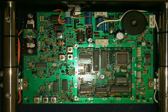
H47-SP2
Apr 01, 1999FAP - Part 15 Anti-Pilferage Device
Equipment Class
FAP - Part 15 Anti-Pilferage DeviceH47-SP1
May 08, 1997Electronic Article Surveillance Transceiver
Equipment Class
FDS - Part 15 Field Disturbance Sensor