H47-SP2
Ketec Inc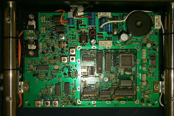
Click to zoom
Application Details
- Equipment Class
- FAP - Part 15 Anti-Pilferage Device
- Date of Grant
- Apr 01, 1999
- Application Purpose
- Original Equipment
- Date of Application
- Feb 28, 1999
- Frequency Range
- 8.20000000 - 8.20000000
- Company
- Ketec Inc
- Country
- United States
Documents & Files
Document Text
Text extracted from the exhibit documents filed with the FCC. Open a document above to read the original.
Users Manual
KETEC SP-2 SYSTEM AND TAG INSTALLATION GUIDE PLEASE READ CAREFULLY KETEC INC. INSTALLATION GUIDE NO. 003 REV.0 © Dec.3, 1998 FCC COMPLIANCE This equipment has been tested and found to comply with the limits stated in Part 15 of the FCC Rules. These limits are designed to provide reasonable protection against harmful interference when the equipment is operated in a commercial environment. This equipment generates, uses, and can radiate radio frequency energy and, if not installed and used in accordance with the instruction manual, may cause harmful interference to radio communications. However, there is no guarantee that interference will not occur in a particular installation. Operation of this equipment in a residential area may cause harmful interference, in which case the user will be required to correct the interference. EQUIPMENT MODIFICATION Any equipment changes or modifications not expressly approved by Ketec Inc. could void the user's authority to operate this equipment under Part 15 of the FCC Rules. Unauthorized changes or modifications will also void any warranty provided by Ketec Inc. WARRANTY DISCLAIMER Ketec Inc. makes no representation or warranty with respect to the contents hereof and specifically disclaims any implied warranties of merchantability or fitness of purpose. Further, Ketec Inc. reserves the right to revise this publication or make changes to its content without obligation to notify any person or company of such revision or change. Copyright 1998 All rights reserved No part of this manual may be reproduced in any form without written permission from Ketec Inc. Installation Before installing any Ketec equipment, check all packing materials to be sure that all parts, hardware, manuals, etc., have been included. Be sure that there is sufficient room to install the system, and that there is a 120VAC outlet within 10 feet of the system. A single aisle system will usually consist of (1) antenna panel and (1) wall-mount power supply. Position the completed assembly at the area that you wish to protect, trying to keep away from any power, telephone, or computer wires. Fasten the antenna to the floor, with the appropriate hardware, through the mounting holes provided in the antenna base. Plug the power supply into an available 120 VAC wall outlet. THAT'S ALL!! SP-2 Antenna Panel 120 VAC Wall-Plug In Power Supply Tagging Guide The SP-2 is a hard and soft tag detection system that will respond to any tags within several feet of the antenna panel. Since the detection field extends from both sides of the panel, it is important to avoid placing any tagged merchandise within the protected area. As a general rule, tags should be at least 6 feet from all sides of the antenna panel. REMEMBER: Hard tags used with this system must be removed at the cash register using the appropriate detacher. Failure to remove any tag will result in an alarm as the customer leaves the store. Tagged Merchandise can Tagged Merchandise can be placed in this area. be placed in this area. Tagged Merchandise can Tagged Merchandise can be placed in this area. be placed in this area.
External Photos
SP-2 Product Description The SP-2 is a hard and soft tag detection system that will detect the presence of resonant RF tags within a protected area. The system consists of an antenna panel with associated internal circuitry and a small power supply. Resonant tags (hard or soft) are applied to the items to be protected. If a tagged item is brought within the protected area, an audible and visual alarm will sound, alerting store personel of a possible theft. Since the detection field extends from both sides of the antenna, care must be exercised in displaying tagged items near the protected zone. December 17, 1998 Federal Communications Commission Washington, DC 20554-1300 Gentlemen: Persuant to 5 U.S.C. 552 (b)(4), and in compliance with 47CFR Part 0, 0.459 regarding material available for public inspection, I request that the following materials relating to FCC grant H47- 5P2 be held confidential and priviledged. Specifically, all schematics, block diagrams, and technical descriptions pertaining to H47-5P2. This material contains confidential trade secrets and priviledged information that could prove harmful to Ketec Inc. if divulged. This material represents a unique approach to Anti-Shoplifting equipment developed by Ketec Inc. to remain in the highly competitive Electronic Article Surveillence marketplace. Disclosure would enable our competitors to benefit directly from our design and development efforts, and would negate the competitive advantage that our product will enjoy by utilizing the techniques contained therein, seriously affecting our ability to do business in this global market. The confidential information contained herein is not available to the public. Internal access is strictly on a need-to-know basis. Access is not available through the company’s internal computer network. All information pertaining to grant number H47-5P2 is stored within a secure area, only accessible to authorized personel. As this industry contains a relatively small number of companies, proprietary improvements and implementations rather than technology changes are the standard. These improvenents and implementations would not be readily discovered by reverse engineering, and may give our company a competitive advantage that would be compromised by disclosure. Requests for this material should be denied for a period of not less than 15 years on this basis. Sincerely, Richard J. Frohbergh Ketec Inc. TECHNICAL DESCRIPTION OF THE SP-2 SYSTEM The SP-2 is a transmitter/receiver/loop antenna combination. The transmitter/receiver is alternately gated on and off. A microprocessor supplies all gating and control signals to insure that the transmitter and receiver are enabled at the proper times. A common loop antenna is shared between the transmitter and the receiver. A narrow enabling pulse generated by the microprocessor is supplied to the transmitter at a rate of 120 Hz. This pulse turns on the transmitter for the pulse duration only. The RF output remains at zero for the remainder of the period. After the transmitter pulse there is a defined waiting period when neither the transmitter nor the receiver is enabled. Following the waiting period, the A/D converter is enabled to initiate the receive function. Data transfer and processing occurs only after the transmitter pulse and the waiting period has expired. Data received by the microprocessor during the receive enabling pulse is analyzed, and if the proper conditions are met, an output to the alarm circuitry is generated. A system block diagram (Ketec Dwg. 5P820 19) showing all oscillator frequencies and functions is attached. ~ONFWEN11AL INFORMAIiWi Of Ketec, Inc.
Operational Description
SP-2 Product Description The SP-2 is a hard and soft tag detection system that will detect the presence of resonant RF tags within a protected area. The system consists of an antenna panel with associated internal circuitry and a small power supply. Resonant tags (hard or soft) are applied to the items to be protected. If a tagged item is brought within the protected area, an audible and visual alarm will sound, alerting store personel of a possible theft. Since the detection field extends from both sides of the antenna, care must be exercised in displaying tagged items near the protected zone. December 17, 1998 Federal Communications Commission Washington, DC 20554-1300 Gentlemen: Persuant to 5 U.S.C. 552 (b)(4), and in compliance with 47CFR Part 0, 0.459 regarding material available for public inspection, I request that the following materials relating to FCC grant H47- 5P2 be held confidential and priviledged. Specifically, all schematics, block diagrams, and technical descriptions pertaining to H47-5P2. This material contains confidential trade secrets and priviledged information that could prove harmful to Ketec Inc. if divulged. This material represents a unique approach to Anti-Shoplifting equipment developed by Ketec Inc. to remain in the highly competitive Electronic Article Surveillence marketplace. Disclosure would enable our competitors to benefit directly from our design and development efforts, and would negate the competitive advantage that our product will enjoy by utilizing the techniques contained therein, seriously affecting our ability to do business in this global market. The confidential information contained herein is not available to the public. Internal access is strictly on a need-to-know basis. Access is not available through the company’s internal computer network. All information pertaining to grant number H47-5P2 is stored within a secure area, only accessible to authorized personel. As this industry contains a relatively small number of companies, proprietary improvements and implementations rather than technology changes are the standard. These improvenents and implementations would not be readily discovered by reverse engineering, and may give our company a competitive advantage that would be compromised by disclosure. Requests for this material should be denied for a period of not less than 15 years on this basis. Sincerely, Richard J. Frohbergh Ketec Inc. TECHNICAL DESCRIPTION OF THE SP-2 SYSTEM The SP-2 is a transmitter/receiver/loop antenna combination. The transmitter/receiver is alternately gated on and off. A microprocessor supplies all gating and control signals to insure that the transmitter and receiver are enabled at the proper times. A common loop antenna is shared between the transmitter and the receiver. A narrow enabling pulse generated by the microprocessor is supplied to the transmitter at a rate of 120 Hz. This pulse turns on the transmitter for the pulse duration only. The RF output remains at zero for the remainder of the period. After the transmitter pulse there is a defined waiting period when neither the transmitter nor the receiver is enabled. Following the waiting period, the A/D converter is enabled to initiate the receive function. Data transfer and processing occurs only after the transmitter pulse and the waiting period has expired. Data received by the microprocessor during the receive enabling pulse is analyzed, and if the proper conditions are met, an output to the alarm circuitry is generated. A system block diagram (Ketec Dwg. 5P820 19) showing all oscillator frequencies and functions is attached. ~ONFWEN11AL INFORMAIiWi Of Ketec, Inc.
Test Report
Intertek Testing Services NA Inc. 593 Massachusetts Avenue Boxborough, MA 01719 Telephone (508) 263-2662 Fax (508) 635-9534 Ketec Inc. Emissions Testing Performed on the Anti-Shoplifting Field Disturbance Transmitter Model: SP2 Date of Test: February 18, 1999 JOB # J99003443A MFM/Rbt KET3443A.MFM February 23, 1999 DOT: February 18, 1999 Contact: Mr. Rich Frohbergh Total No. of Pages Contained in this Report: All services undertaken are subject to the following general policy: Reports are submitted for exclusive use of the client to whom they are addressed. Their significance is subject to the adequacy and representative character of the samples and to the comprehensiveness of the tests, examinations or surveys made. No quotations from reports or use of Intertek Testing Services name is permitted except as expressly authorized by Intertek Testing Services in writing. INTERTEK TESTING SERVICES NA INC. TO:Ketec Inc. Mr. Rich Frohbergh FROM:Kouma P. Sinn DATE:February 18, 1999 RE:Emissions Testing Performed On The Anti-Shoplifting Field Disturbance Transmitter, Model: SP2 On February 18, 1999 we tested the Anti-Shoplifting Field Disturbance Transmitter, Model SP2 to determine if it was in compliance with the FCC Part 15 requirements, Subpart C, '15.223. A production version of the sample was received on February 18, 1999 was in good condition. We found that the unit met the Part 15 requirements when tested as received. Present during the testing from Ketec Inc. was Mr. Rich Frohbergh. Fundamental and Harmonics (10 kHz to 30 MHz) The fundamental transmit frequency was 12.5 dB below the FCC Part 15, Subpart C, '15.223 requirement at 8.2 MHz. All other emissions were at least 17.5 dB below the applicable limits (see Table 1). Please note that an average factor of 20 dB was applied to the level of emissions for comparison to the FCC limits. Average factor calculation and corresponding plots are included in the average factor section of this report. Spurious Emissions (30 MHz to 1 GHz) The radiated emissions was 6 dB below the Part 15 requirements at 30.00 MHz. All other emissions were at least 8 dB below the applicable limits (see Table 2). Line-Conducted Emissions The worst-case line-conducted emissions were 25 dB below the Part 15 requirements at 24.95 MHz and 25.70 MHz. All other emissions were at least 37 dB below the applicable limits (see Table 3). Summary INTERTEK TESTING SERVICES NA INC. TO:Ketec Inc. Mr. Rich Frohbergh FROM:Kouma P. Sinn DATE:February 18, 1999 RE:Emissions Testing Performed On The Anti-Shoplifting Field Disturbance Transmitter, Model: SP2 In summary, this report confirms that the SP2 is compliant with the FCC Part 15, Subpart C, '15.223 requirements when production units conform with the initial sample. Please address all questions and comments concerning this report to Andrew J. Bellezza, Staff Engineer/Emissions. INTERTEK TESTING SERVICES NA INC. Laboratory Measurements, Intentional Radiators Rev. September 1, 1992 (PT15C.IR) Introduction The following is a description of the test procedure used by Intertek Testing Services in the measurements of transmitters operating under Part 15, Subpart C, General Requirements. A.Test Set-Up: The test set-up and procedures described below are designed to meet the requirements of ANSI C63.4 (1992). 1.The test site is a wooden structure with a groundplane. The site has attenuation characteristics which meet the requirements of ANSI C63.4 (1992). Information on the site has been filed with the FCC as required by Rule '2.948. The address of the site is 70 Codman Hill Road, Boxborough, Massachusetts. 2.Power to the site is nominal line voltage of 117 V AC and 230 V AC , 60 Hz. 3.The equipment under test (EUT) is placed on a wooden turntable which is four feet in diameter and approximately one meter in height above the groundplane. During the radiated emissions test, the turntable is rotated and any cables leaving the EUT are manipulated to find the configuration resulting in maximum emissions. The antenna height and polarization are also varied during the search for maximum signal levels. The height of the antenna is varied from one meter to four meters. 4.Detector function for radiated emissions is in peal or quasi-peak mode. Average readings, when required, are taken by measuring the duty cycle of the equipment under test and subtracting the corresponding amount in dB from the measured peak readings according to the following formula: Averaging Factor in dB = 20 LOG (duty cycle) INTERTEK TESTING SERVICES NA INC. Laboratory Measurements, Intentional Radiators Rev. September 1, 1992 (PT15C.IR) A.Test Set Up (cont'd) The time period over which the duty cycle is measured is 100 msec. The worst-case (highest percentage on) duty cycle is used and described specifically in the data section. The duty cycle is measured by placing the spectrum analyzer in zero scan (receiver mode) and linear mode at maximum bandwidth (3 MHz at 3 dB down) and viewing the resulting time domain signal output from the analyzer on a Tektronix 465 Oscilloscope. The oscilloscope is used because of its superior time base and triggering facilities. A drawing or photograph of the worst-case duty cycle as detected in this manner is included as an attached page. 5.Antennas used below 1000 MHz was EMCO Biconolog Antenna. For measurements between 1000 MHz and 18000 MHz, where required, an Emco Double-Ridge Guide Horn Antenna was used. Alternately, for measurements above 1 GHz, an EMCO M/N 3115 Horn Antenna may have been used. 6.The field strength measuring equipment used included: Spectrum Analyzer:Hewlett Packard 8593A Preamplifier:CDI P-950 LISN:Solar Electronics Additional equipment or comments: Equipment is calibrated at frequent intervals. INTERTEK TESTING SERVICES NA INC. Laboratory Measurements, Intentional Radiators Rev. September 1, 1992 (PT15C.IR) A.Test Set Up (cont'd) 7.The frequency range to be scanned is from the lowest radio frequency signal generated in the…
Text truncated - open the document above for the full version.
Contact Information
Applicant
Richard J Frohbergh(Product Engineer)
Technical Contact
Intertek Testing Services NA Inc.Andrew J Bellezza
[email protected]978-263-2662
70 Codman Hill Road · Boxborough, Massachusetts · United States
Non-Technical Contact
Intertek Testing Services NA Inc.Jody K Zarnowiec
[email protected]978-263-2662
Test Firm
Intertek Testing Services NA Inc.Diana Montvitt
508-263-2662
Technical Specifications
| # | Rule Parts | Frequency Range | Power Output |
|---|---|---|---|
| 1 | 15C | 8.2 MHz - 8.2 MHz | - |
Other Applications from Ketec Inc

H47-PHAZOR
Sep 10, 2007Anti-Shoplifting Field Disturbance Transmitter
Equipment Class
FAP - Part 15 Anti-Pilferage Device
H47-K2000
Aug 15, 2001K2000 EAS Tag Deactivator
Equipment Class
DSR - Part 15 Remote Control/Security Device TransceiverH47-SP1
May 08, 1997Electronic Article Surveillance Transceiver
Equipment Class
FDS - Part 15 Field Disturbance Sensor