H5OR40Car Alarm Receiver
Advance Security Inc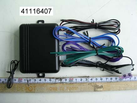
Click to zoom
Application Details
- Equipment Class
- CRR - Superregenerative Receiver
- Date of Grant
- Nov 28, 2004
- Application Purpose
- Original Equipment
- Date of Application
- Nov 28, 2004
- Equipment Note
- Car Alarm Receiver
- Frequency Range
- 433.92000000 - 433.92000000
- Company
- Advance Security Inc
- Country
- Taiwan
Documents & Files
Document Text
Text extracted from the exhibit documents filed with the FCC. Open a document above to read the original.
Users Manual
CE400 Transmitter Operation and Programming • Programming transmitter This receiver/Module can program up to 4 different transmitters for each channel output Enter: 1. Use a small screwdriver to press the programming switch until the LED start to flash (about 2 seconds) the release 2. Within 10 seconds press any transmitter button and hold it until the LED solid on (The transmitter programmed), then release the button. 3. Wait until the LED flashing again. 4. To program second ~ fourth transmitters, wait got LED flashing again and repeat steps 2 ~ 3. Exit: 1. Press the program switch 1 times again. (Blue LED turn-off) 2. Or, leave it for about 10 seconds, it will automatically exit. Note: If more than 4 transmitter’s codes programmed, the system only keeps the very last 4 codes. The previous codes will void automatically. (eg. You already programmed 4 codes into the system. You may program additional codes No. 5 and 6 into the system, the codes No. 1 and 2 will be void while codes No 3 ~ 6 stays. • Programming timer output: This receiver/module can select 6 different timer output modes Enter: 1. Use a small screwdriver to press the programming switch and hold it until the LED starts flashing slow (about 2 second), then release 2. Then press programming switch 3-times again 3. The LED will start to flash, and the timer output programming mode status (see below chart) 4. Push the transmitter button (The one you just programmed) to select desirable output timer mode. 5. If LED with 1 flash ... pause (0.5-second mode). To select the next mode press the button one time to change to the next timing output, that is 1.0-second mode. 6. If LED with 5 flashes ... pause (Momentary mode), to select 1-second mode, press the button 3 times. Output Timer Mode LED Status 0.5 second timer output 1 flash ... pause 1 second timer output 2 flash ... pause 2 second timer output 3 flash ... pause 3 second timer output 4 flash ... pause Momentary pulse output 5 flashes ... pause Latch output 6 flashes ... pause Note: In each mode the LED will flash 5 times, (eg. In latch mode, LED will flash, "6 flashes ... pause" for 5 times.) Allowing you to check the current mode status. If there is no transmitter button pressed over the 9 times flashing, the system would automatically exit the programming timer output. Exit: 1. Press the program switch again. (LED off) 2. Or, leave the LED to flash for 5 times, it will automatically exit. CE400 The above 4 channel are individual. The methods of Programming transmitter and Programming timer output are the same • Relay Output 1. Unit has 4-output (4-channels) by relay that has N/C, COM, and N/O 2. The relays are 10Amp 3. Each channel output can programmable independently • The Color wire of Output Channel 1: N/C --- Blue/Red COM --- Blue N/O --- Blue/White Channel 2: N/C --- Green/Red COM --- Green N/O --- Green/White Channel 3: N/C --- Purple/Red COM --- Purple N/O --- Purple/White Channel 4: N/C --- Black/Red COM --- Black N/O --- Black/White This receiver/Module is design to remote control a garage door, trunk release motor, window roll up/down module & other electronic equipment (included home security) • Instruction Idea Ex. Channel 1 These wires are connected to the terminals of the on-board Channel 1 Relay. When the control module receivers the code programmed into Channel 1, this relay activated. Blue Wire: Relay common, terminal #30. Blue/White Wire: Relay normally open, terminal #87. Blue/Red Wire: Relay normally close, terminal #87A To interface with a garage door opener, first determine if the garage door opener’s wall awitch connects (normally open switch type), or disconnects the wires (normally closed switch type). Most garage door openers use a normally closed switch. Once the switch type has been determined, interface with the module as shown in the following diagrams. Blue/White Wire #30 Blue Wire #87 NORMALLY OPEN SWITCH To Garage Door Opener Blue Wire #30 Blue/Red Wire #87A NORMALLY CLOSED SWITCH To Garage Door Opener CUT This device complies with part 15 of the FCC rules. Operation is subject to the following two conditions. (1)This device may not cause harmful interference, and (2)This device must accept any interference received, including interference that may cause undesired operation. Per FCC 15.21, you are cautioned that changes or modifications not expressly approved by the part responsible for compliance could void the user’s authority to operate the equipment.
Block Diagram
1 2 34 ABCD 4 3 2 1 D CBA 12V INPUT SW1 CHANNEL 1 O/P LED1 OUTPUT Title Size Orcad ADate File Number 2004-8-20 E:\DDB\CE400-1A.DDB Revision Sheet of Drawn By : DATA O/P SW2 SW3 SW4 CHANNEL 2 O/P CHANNEL 3 O/P CHANNEL 4 O/P LED2 OUTPUT LED3 OUTPUT LED4 OUTPUT
External Photos
Compliance Certification Services Inc. Report No: 41116407-RP1 Date of Issue: November 23, 2004 1 . 00 Compliance Certification Services Inc. Report No: 41116407-RP1 Date of Issue: November 23, 2004 2 . 00
ID Label/Location Info
FCC ID LABEL FORMAT AND LOCATION Applicant: Advance Security Inc. FCC ID: H5OR40 Model: CE400 Trade Name:Advance Securit y Inc. This device complies with part 15 of the FCC Rules. Operation is subject to the following two conditions: (1) This device may not cause harmful interference, and (2) this device must accept any interference received, including interference that may cause undesired operation. FCC ID: H5OR40 FCC ID LABEL AREA
Internal Photos
Compliance Certification Services Inc. Report No: 41116407-RP1 Date of Issue: November 23, 2004 1 . 00 Compliance Certification Services Inc. Report No: 41116407-RP1 Date of Issue: November 23, 2004 2 . 00
Schematics
CS 1 CK 2 DI 3 DO 4 GND 5 NC 6 NC 7 VDD 8 VI GND VO +12V B+ 5V 5V PA3 1 PA1 3 PB1 5 OSC2 16 PA6 18 PA4 20 PA2 2 PC1 9 PC0 8 VSS 7 PB0 6 PA0 4 PC4 12 RES 13 VDD 14 OSC1 15 PA7 17 PA5 19 PC2 10 PC3 11 +- 56 7 +- 32 1 84 B+ B+ B+ B+ 5V 123 123 123 123 5V 5V 5V 5V5V 5V5V 5V A A A
Test Report
Compliance Certification Services Inc. Report No: 41116407-RP1 Date of Issue: November 23, 2004 Page 1 of 13 00 FCC ELECTROMAGNETIC EMISSIONS COMPLIANCE REPORT CERTIFICATION TO FCC PART 15 REQUIREMENTS for Car Alarm Receiver FCC ID Number : H5OR40 Trade Name : Advance Security Inc. Model Number : CE400 Agency Series : N/A Report Number : 41116407-RP1 Date : November 23, 2004 Prepared for Advance Security Inc. 3F, 48 Ta An Street, Hsi Chih, Taipei Hsien, Taiwan, R.O.C. Prepared by Compliance Certification Services Inc. Hsintien Lab. No. 165, Chunghsen Road, Hsintien City Taipei Hsien, Taiwan TEL: (02) 2217-0894 FAX: (02) 2217-1029 This report shall not be reproduced, except in full, without the written approval of Compliance Certification Services Inc. Compliance Certification Services Inc. Report No: 41116407-RP1 Date of Issue: November 23, 2004 2 . 00 TABLE OF CONTENTS 1. VERIFICATION OF COMPLIANCE .......................................................... 3 2. PRODUCT DESCRIPTION............................................................................ 4 3. TEST FACILITY.............................................................................................. 4 4. MEASUREMENT EQUIPMENT USED ...................................................... 4 5. TEST CONFIGURATION .............................................................................. 5 6. TESTS CONDUCTED ..................................................................................... 5 7. RADIATED EMISSION TEST PROCEDURE ........................................... 5 8. COHERENT TESTS ........................................................................................ 6 9. EQUIPMENT MODIFICATIONS................................................................. 6 APPENDIX 1 ................................................................................................................ 7 APPENDIX 2 ................................................................................................................ 9 APPENDIX 3 .............................................................................................................. 13 Compliance Certification Services Inc. Report No: 41116407-RP1 Date of Issue: November 23, 2004 3 . 00 1. VERIFICATION OF COMPLIANCE COMPANY NAME : Advance Security Inc. 3F, 48 Ta An Street, Hsi Chih, Taipei Hsien, Taiwan, R.O.C. CONTACT PERSON : Michael Chen / President TELEPHONE NO. : (886-2) 8648-1688 EUT DESCRIPTION : Car Alarm Receiver MODEL NAME/NUMBER : CE400 FCC ID : H5OR40 DATE TESTED : November 17, 2004 REPORT NUMBER : 41116407-RP1 TYPE OF EQUIPMENT SECURITY EQUIPMENT EQUIPMENT TYPE 433.92 MHz Car Alarm Receiver MEASUREMENT PROCEDURE ANSI 63.4 / 2003 LIMIT TYPE CERTIFICATION FCC RULE CFR 47, PART 15.109 The above equipment was tested by Compliance Certification Services Inc. for compliance with the requirements set forth in the FCC CFR 47, PART 15. The results of testing in this report apply to the product/system which was tested only. Other similar equipment will not necessarily produce the same results due to production tolerance and measurement uncertainties. Warning: This document reports conditions under which testing was conducted and results of tests performed. This document may not be altered or revised in any way unless done so by Compliance Engineering Services, Inc. and all revisions are duly noted in the revisions section. Any alteration of this document not carried out by Compliance Certification Services Inc. will constitute fraud and shall nullify the document. Approved by: Reviewed by: Compliance Certification Services Inc. Report No: 41116407-RP1 Date of Issue: November 23, 2004 4 . 00 2. PRODUCT DESCRIPTION Advance Security Inc., Model No: CE400 is the receiving portion of a multi-purpose security device. The associated transmitter is manufactured by Advance Security Inc., model no: TX555, FCC ID: H5OT21. 3. TEST FACILITY The open area test sites and conducted measurement facilities used to collect the radiated data are located at No. 165 & No. 199, Chung Sheng Road, Hsin Tien City, Taipei, Taiwan R.O.C. The sites are constructed in conformance with the requirements of ANSI C63.7, ANSI C63.4 and CISPR Publication 22. The measuring instrument which was utilized in performing the tests documented herein has been calibrated in accordance with the manufacturer's recommendations for utilizing calibration equipment which is traceable to recognized national standards. 4. MEASUREMENT EQUIPMENT USED Manufacturer Model Number Description Cal Due Date CCS E Site SITE NSA 09/10/2005 R&S DSAI-D / ESBI-RF EMI TEST RECEIVER 03/08/2005 SCHAFFNER CBL 6112B ANTENNA 09/25/2005 H.P. 8447D A AMPLIFIER 04/30/2005 BELDEN 9913 CABLE 03/05/2005 TFA N/A THERMO-HYGRO METER 11/09/2005 Compliance Certification Services Inc. Report No: 41116407-RP1 Date of Issue: November 23, 2004 5 . 00 5. TEST CONFIGURATION Set frequency generator to 433.92 MHz. EUT receiving transmission continuously. All the wires are placed on the turn table to their maximum length to simulate the worse emission conditions. 6. TESTS CONDUCTED CFR 47, 15.109 RADIATED EMISSION TESTS RADIATED AT 3 METERS 7. RADIATED EMISSION TEST PROCEDURE The EUT and all other support equipment are placed on a wooden table 80 cm above the ground screen. Antenna to EUT distance is 3 meters. During the test, the table is rotated 360 degrees to maximize emissions and the antenna is positioned from 1 to 4 meters above the ground screen to further maximize emissions. The antenna is polarized in both vertical and horizontal positions. Monitor the frequency range of interest at a fixed antenna height and EUT azimuth. Frequency span should be small enough to easily differentiate between broadcast stations and intermittent ambients. Rotate EUT 360 degrees to maximize emissions received from EUT. If emission increases by more than 1 dB, or if another emission appears that is greater by 1 dB, return to azimuth where maximum occurred and perfo…
Text truncated - open the document above for the full version.
Test Setup Photos
Compliance Certification Services Inc. Report No: 41116407-RP1 Date of Issue: November 23, 2004 1 . 00 RADIATED EMISSION TEST
Contact Information
Applicant
Michael Chen(SAL)
Test Firm
Compliance Certification Services Inc.Kurt Chen
Technical Specifications
| # | Rule Parts | Frequency Range | Power Output |
|---|---|---|---|
| 1 | 15B | 433.92 MHz - 433.92 MHz | - |
Other Applications from Advance Security Inc
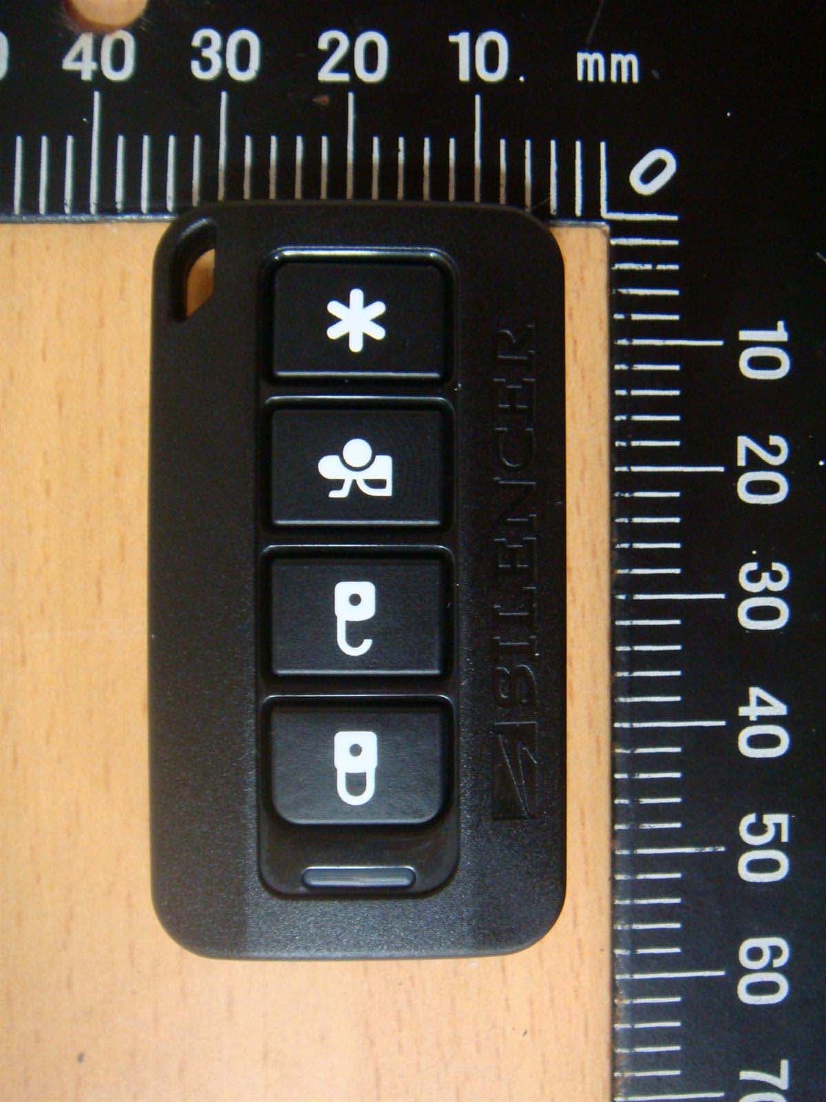
H5OT62
Dec 11, 2015Remote Control
Equipment Class
DSC - Part 15 Security/Remote Control Transmitter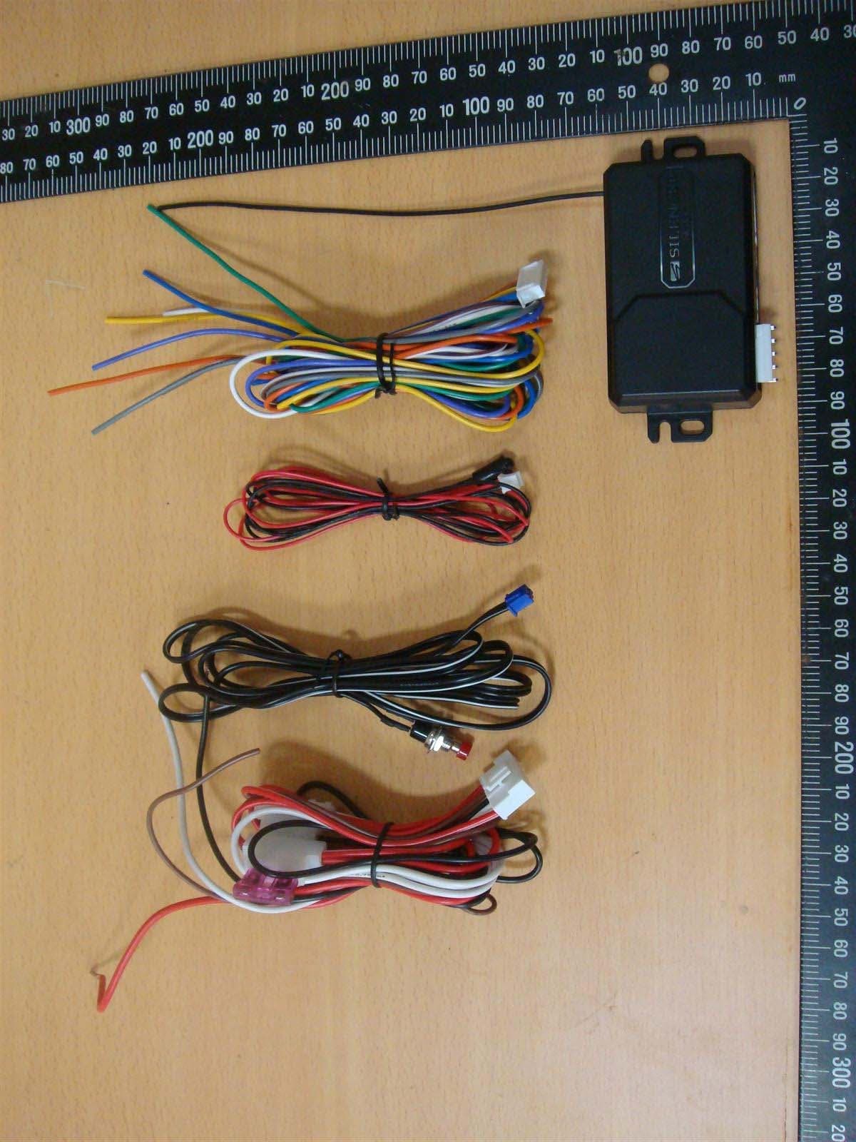
H5OR57
Dec 11, 2015Remote Control
Equipment Class
CYY - Communications Receiver used w/Pt 15 Transmitter
H5OTR64
Oct 22, 2015Remote Control
Equipment Class
DSS - Part 15 Spread Spectrum Transmitter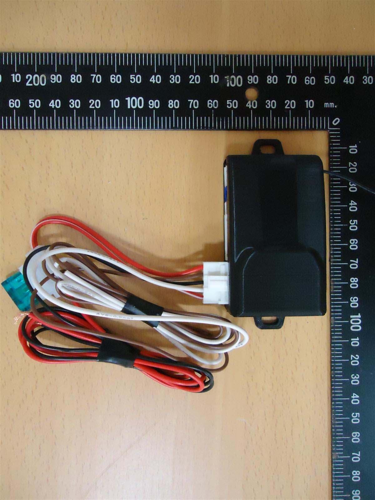
H5OR56
Sep 10, 2015Remote Control
Equipment Class
CYY - Communications Receiver used w/Pt 15 Transmitter
H5OT61
Sep 07, 2015Remote Control
Equipment Class
DSC - Part 15 Security/Remote Control Transmitter