H5OR43Car Alarm Receiver
Advance Security Inc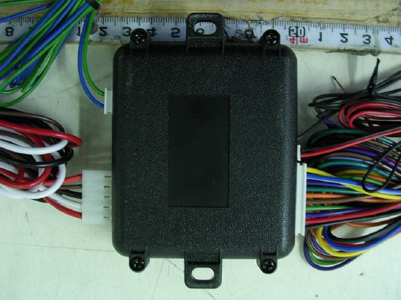
Click to zoom
Application Details
- Equipment Class
- CRR - Superregenerative Receiver
- Date of Grant
- Dec 13, 2004
- Application Purpose
- Original Equipment
- Date of Application
- Dec 13, 2004
- Equipment Note
- Car Alarm Receiver
- Frequency Range
- 433.92000000 - 433.92000000
- Company
- Advance Security Inc
- Country
- Taiwan
Documents & Files
Document Text
Text extracted from the exhibit documents filed with the FCC. Open a document above to read the original.
Users Manual
APRIL /29/2004 400S 1 MODEL CS400S REMOTE CONTROL SECURITY SYSTEM INSTALLATION & OPERATION INSTRUCTIONS WIRING DIAGRAM H1: Main 5 Pin White Harness H7 : 10 Pin White Mini Connector Black Antenna Wire LED Indicator Valet Switch Green: (-) 200mA Lock Pulse or (+) Unlock Pulse Blue: (-) 200mA Unlock Pulse or (+) Lock Pulse H4 3 Pin White H2 4 Pin Orange H3 2 Pin Blue H6 2 Pin White H5 Black Wire Dual Zone Shock Sensor H1 5 Pin White H7 10 Pin White H1: MAIN 5 PIN WIRE HARNESS: 5. Red Wire: +12V To Constant Battery Source 4. Brown Wire: Positive output To Siren 3. Black Wire: Ground to Vehicle Frame 2. White Wire: Parking Light Relay Output 1. Red / White Wire: Parking Light Relay Power Input 3A Fuse 10A Fuse H7: 10 PIN MINI CONNECTOR WIRE HARNESS: APRIL /29/2004 400S 2 4. Green Wire: Zone 3 / Negative Door Pin Trigger Input. 2. Blue / White Wire: Zone 2 / Instant Trigger Ground Input 3. Violet Wire: Zone 3 / Positive Door Pin Trigger Input 1. Yellow Wire: Zone 5 / To Ignition Switched + 12V 5. Orange Wire: (-)200mA Grounded Output When Armed 7. LT Green / Black Wire: (-) 200mA of 2 Steps Door Unlock Output. 9. Red / White Wire: (-)200mA Channel 3 (Trunk) Output 10. Black / White Wire: (-) 200mA of Dome Light Output 6. Brown / Black Wire: (-) 200mA Horn Output +12 +12 8. Purple / Black Wire: (-) 200mA Timer Control Channel 4 Output WIRING Keep wiring away from moving engine parts, exhaust pipes and high-tension cable. Tape wires that pass through holes on the firewall to prevent fraying. Watches out sharp edges that may damage wires and causes short circuit. CAUTION: Do not connect the wire harness to the control module until all wiring to vehicle is complete. H1. MAIN 5 PIN WIRE HARNESS: H1/1. Red / White wire – Parking Light Relay Input – The RED/WHITE wire is the input to the flashing parking light relay. The connection of the RED/WHITE wire will determine the output polarity of the flashing parking light relay. If the vehicle you are working on has +12volt switched parking light, you don’t need connect this wire. This wire already connected to +12volt. If the vehicle’s parking light with ground switched, cut the RED/WHITE wire, connect the RED/WHITE wire to chassis ground. H1/2. White wire – Parking Light Relay Output (+12 V 10A Output) – Connect the WHITE wire to the parking light wire coming from the headlight switch. Do not connect the WHITE wire to the dashboard lighting dimmer switch. (Damage to the dimmer will result). The limitation of the WHITE wire is 10 Amp max. Do not exceed this limit or damage to the alarm and parking relay will result. H1/3. Black wire – System Ground – This is main ground connection of the alarm module. Make this connection to a solid section of the vehicle frame. Do not connect this wire to any existing ground wires supplied by the factory wire loom, make the connection to the vehicle's frame directly. H1/4. Brown wire – Siren Drive or Horn Output – (Set Feature III – 2 Programming) SIREN DRIVE OUTPUT (Factory default setting) This is the positive (+) output connection for the siren. Current capacity is 2 Amp. Make connection to the (+) red wire from the siren. Make the (-) black wire coming from the siren to a good chassis ground. (+) Low Current HORN OUTPUT -- (Set Alarm Feature III – 2 To Horn Output) This wire is provided to use the existing vehicle's horn as the alarm system's optional warning audible device. It's a transistorized low current output, and should only be connected to the low current positive (+) output from the vehicle's horn switch. H1/5. Red wire – System Power (+12V Constant) – The RED wire supplies power to the system. Connect this wire to a constant +12 volt source. H2. 4 PIN ORANGE CONNECTOR FOR 2 STAGE SHOCK SENSOR APRIL /29/2004 400S 3 4. Green Wire / Warn Away Input 3. Blue Wire / Zone 4 Ground Trigger 2. Black Wire / Negative 1. Red Wire / +12Volts H5. RF ANTENNA - BLACK THIN WIRE The black thin wire on control module is the receiver antenna wire. Antenna placement is very important! Ensure that it is unwrapped and stretched out with the last 6" straight and keep it away from large metal objects or chassis for best reception. H7. 10-PIN MINI CONNECTOR WIRE HARNESS. H7/1 Yellow wire – To Ignition Switched +12V – This wire is connected to a switched 12 volts source. This wire should receive "12 volts" when the ignition key is in the "ON" and "START" position. When the ignition is turned "OFF", this wire should receive "0" voltage. H7/2. Blue / White wire – (-) Instant Trigger or Major trigger Input (Zone 2) – This wire is the ground trigger input wire for hood/trunk pin switches. H7/3. Violet wire – Positive Door Switch Sensing Input – This wire is the positive trigger input wire for positive door pin switch. This wire is connection for "positive" type factory door pins(typical FORD MOTOR). Locate the "common wire" for all door pins and make the connection of the Violet Wire here. H7/4. Green wire – Negative Door Switch Sensing Input – This wire is the ground trigger input wire for negative door pin switch. This wire is connection for "grounding" type factory door pins locate the "common wire" that connects the door pin switches. Make the connection of the GREEN Wire here. H7/5. Orange wire – (-) 200mA Grounded Output When Armed – This wire will become grounded when the alarm is armed. The current capacity of this wire is 200mA. This output can control starter disable, when an intrusion is detected and the system is triggered. The vehicles prevent from any unauthorized starting. a). Find the wire from the starter solenoid, (usually located on the starter) and going to the ignition switch. b). When found, use voltmeter, connect one probe of the voltmeter to ground and connect the other end of the probe to the starter wire, it should receive "12 volts" only when the ignition key in the "START" position. c). After locating the correct wire, cut it in half, try to start the vehicle. The engine should not "crank over". d). When the …
Text truncated - open the document above for the full version.
Block Diagram
1 2 34 ABCD 4 3 2 1 D CBA 12V INPUT IGNITION DATA O/P PIN SW1 PIN SW2DOOR SW OVERRIDE SW SIREN OUTPUT PARKING LIGHT ARM OUTPUT CHANNEL 3 OUTPUT DOOR LOCK OUTPUT DOOR UNLOCK OUTPUT LED OUTPUT WARN-AWAY 2-STEP D/UL OUTPUT HORN OUTPUT DOMELIGHT OUTPUT CHANNEL 4 OUTPUT Title Size Orcad ADate File Number 2004-8-06 E:\DDB\400S-1B.DDB Revision Sheet of Drawn By :
Cover Letter(s)
Helen Zhao Subject: FW: FW: ADVANCE SECURITY INC., FCC ID: H5OR43, Assessment NO.: AN04T4400, Notice#1 12/14/2004 -----Original Message----- From: [email protected] [mailto:[email protected]] Sent: Tuesday, December 14, 2004 5:45 PM To: Helen Zhao Subject: Re: FW: ADVANCE SECURITY INC., FCC ID: H5OR43, Assessment NO.: AN04T4400, Notice#1 Dear Helen: Question #1: FCC ID label format includes FCC DoC logo, which is not applicable in this case, please remove the FCC DoC logo from the label format. --->Sorry about that! Attached please find FCC ID LAB.pdf! Question #2: The user manual does not contain warning statement(Information to the User) as specified in FCC 15.21. Please revise the user manual. --->Sorry about that! Attached please find User's Manual.pdf! Question #3: The test report indicated that "The associated transmitter is manufactured by Advance Security Inc., FCC ID: H5OR43", but Form 731 indicated that the associated transmitter is FCC ID: H5OT21. Please correct the report. --->Sorry about that! Attached please find Test Report.pdf! Thank you very much for your information. Best regards, Eva Fan
External Photos
Compliance Certification Services Inc. Report No.: 41129404-RP1 Date of Issue: December 7, 2004 10 . 00
ID Label/Location Info
FCC ID LABEL FORMAT AND LOCATION Applicant: Advance Security Inc. FCC ID: H5OR43 FCC ID: H5OR43 This device complies with part 15 of the FCC Rules. Operation is subject to the following two conditions: (1) This device may not cause harmful interference, and (2) this device must accept any interference received, including interference that may cause undesired operation. FCC ID LABEL AREA
Internal Photos
Compliance Certification Services Inc. Report No.: 41129404-RP1 Date of Issue: December 7, 2004 11 . 00 Compliance Certification Services Inc. Report No.: 41129404-RP1 Date of Issue: December 7, 2004 12 . 00
Operational Description
(CS400S) Operational Description The radio frequency car-alarm is a system that it controllers locking(arm) and unlocking(disarm) the door of vehicle by wireless remote controller. This system consists of transmitter and receiver. The receiver (EUT) is fixed inside the vehicle and powered 12V from car battery. It works intermittently to prevent the battery exhaustion and check the vehicle status. It is designed to operate on a single fixed frequency 433.92 MHz by frequency modulation. It runs continuously to receive the signals completely, when the receiving module in receiver detects several synchronous codes, unique identification code, security code and function code transmitted from transmitter. After receiving the signal, the 8bit CPU in receiver decides which operation will be performed. And then driving circuit in receiver performs selected operations by pressing the button of the remote transmitter. All tuning and verification are performed by the manufacturer and there are no adjustments which can be made by the user. External ground is the chassis of vehicle and receiving antenna is fixed on enclosure of the receiver.
Schematics
Title Size 1500x1020Date File Number 2004-08-06 E:\DDB\400SS-1A.DDB Revision Sheet of Drawn By : RE2 RE1 CSCKDIO
Test Report
Compliance Certification Services Inc. Report No.: 41129404-RP1 Date of Issue: December 7, 2004 Page 1 of 13 00 FCC ELECTROMAGNETIC EMISSIONS COMPLIANCE REPORT CERTIFICATION TO FCC PART 15 REQUIREMENTS for Car Alarm Receiver FCC ID Number : H5OR43 Trade Name : Advance Security Inc. Model Number : CS400S Agency Series : N/A Report Number : 41129404-RP1 Date : December 7, 2004 Prepared to Advance Security Inc. 3F, 48 Ta An Street, Hsi Chih, Taipei Hsien, Taiwan, R.O.C. Prepared by Compliance Certification Services Inc. Hsintien Lab. No. 165, Chunghsen Road, Hsintien City Taipei Hsien, Taiwan TEL: (02) 2217-0894 FAX: (02) 2217-1029 This report shall not be reproduced, except in full, without the written approval of Compliance Certification Services Inc. Compliance Certification Services Inc. Report No.: 41129404-RP1 Date of Issue: December 7, 2004 2 . 00 TABLE OF CONTENTS 1. VERIFICATION OF COMPLIANCE..............................................................................3 2. PRODUCT DESCRIPTION..............................................................................................4 3. TEST FACILITY................................................................................................................4 4. MEASUREMENT EQUIPMENT USED.........................................................................4 5. TEST CONFIGURATION.................................................................................................5 6. TESTS CONDUCTED.......................................................................................................5 7. RADIATED EMISSION TEST PROCEDURE...............................................................5 8. COHERENT TESTS..........................................................................................................6 9. EQUIPMENT MODIFICATIONS...................................................................................6 Compliance Certification Services Inc. Report No.: 41129404-RP1 Date of Issue: December 7, 2004 3 . 00 1. VERIFICATION OF COMPLIANCE COMPANY NAME : Advance Security Inc. 3F, 48 Ta An Street, Hsi Chih, Taipei Hsien, Taiwan, R.O.C. CONTACT PERSON : Michael Chen / President TELEPHONE NO. : (886-2) 8648-1688 EUT DESCRIPTION : Car Alarm Receiver MODEL NAME/NUMBER : CS400S FCC ID : H5OR43 DATE TESTED : December 2, 2004 REPORT NUMBER : 41129404-RP1 TYPE OF EQUIPMENT SECURITY EQUIPMENT EQUIPMENT TYPE 433.92 MHz Car Alarm Receiver MEASUREMENT PROCEDURE ANSI 63.4 / 2003 LIMIT TYPE CERTIFICATION FCC RULE CFR 47, PART 15.109 The above equipment was tested by Compliance Certification Services Inc. for compliance with the requirements set forth in the FCC CFR 47, PART 15. The results of testing in this report apply to the product/system which was tested only. Other similar equipment will not necessarily produce the same results due to production tolerance and measurement uncertainties. Warning: This document reports conditions under which testing was conducted and results of tests performed. This document may not be altered or revised in any way unless done so by Compliance Engineering Services, Inc. and all revisions are duly noted in the revisions section. Any alteration of this document not carried out by Compliance Certification Services Inc. will constitute fraud and shall nullify the document. Approved by: Reviewed by: Compliance Certification Services Inc. Report No.: 41129404-RP1 Date of Issue: December 7, 2004 4 . 00 2. PRODUCT DESCRIPTION Advance Security Inc., Model No: CS400S is the receiving portion of a multi-purpose security device. The associated transmitter is manufactured by Advance Security Inc., FCC ID: H5OT21. 3. TEST FACILITY The open area test sites and conducted measurement facilities used to collect the radiated data are located at No. 165 & No. 199, Chung Sheng Road, Hsin Tien City, Taipei, Taiwan R.O.C. The sites are constructed in conformance with the requirements of ANSI C63.7, ANSI C63.4 and CISPR Publication 22. The measuring instrument which was utilized in performing the tests documented herein has been calibrated in accordance with the manufacturer's recommendations for utilizing calibration equipment which is traceable to recognized national standards. 4. MEASUREMENT EQUIPMENT USED Manufacturer Model Number Description Cal Due Date CCS E Site SITE NSA 09/10/2005 R&S DSAI-D / ESBI-RF EMI TEST RECEIVER 03/08/2005 SCHAFFNER CBL 6112B ANTENNA 09/25/2005 H.P. 8447D A AMPLIFIER 04/30/2005 BELDEN 9913 CABLE 03/05/2005 TFA N/A THERMO-HYGRO METER 11/09/2005 Compliance Certification Services Inc. Report No.: 41129404-RP1 Date of Issue: December 7, 2004 5 . 00 5. TEST CONFIGURATION Set frequency generator to 433.92 MHz. EUT receiving transmission continuously. All the wires are placed on the turn table to their maximum length to simulate the worse emission conditions. 6. TESTS CONDUCTED CFR 47, 15.109 RADIATED EMISSION TESTS RADIATED AT 3 METERS 7. RADIATED EMISSION TEST PROCEDURE The EUT and all other support equipment are placed on a wooden table 80 cm above the ground screen. Antenna to EUT distance is 3 meters. During the test, the table is rotated 360 degrees to maximize emissions and the antenna is positioned from 1 to 4 meters above the ground screen to further maximize emissions. The antenna is polarized in both vertical and horizontal positions. Monitor the frequency range of interest at a fixed antenna height and EUT azimuth. Frequency span should be small enough to easily differentiate between broadcast stations and intermittent ambients. Rotate EUT 360 degrees to maximize emissions received from EUT. If emission increases by more than 1 dB, or if another emission appears that is greater by 1 dB, return to azimuth where maximum occurred and perform additional cable manipulation to further maximize received emission. Move antenna up and down to further maximize suspected highest amplitude signal. If emission increased by 1 dB or more, or if another emission appears that is greater by…
Text truncated - open the document above for the full version.
Test Setup Photos
Compliance Certification Services Inc. Report No.: 41129404-RP1 Date of Issue: December 7, 2004 8 . 00 RADIATED EMISSION TEST
Contact Information
Applicant
Michael Chen(SAL)
Test Firm
Compliance Certification Services Inc.Kurt Chen
Technical Specifications
| # | Rule Parts | Frequency Range | Power Output |
|---|---|---|---|
| 1 | 15B | 433.92 MHz - 433.92 MHz | - |
Other Applications from Advance Security Inc
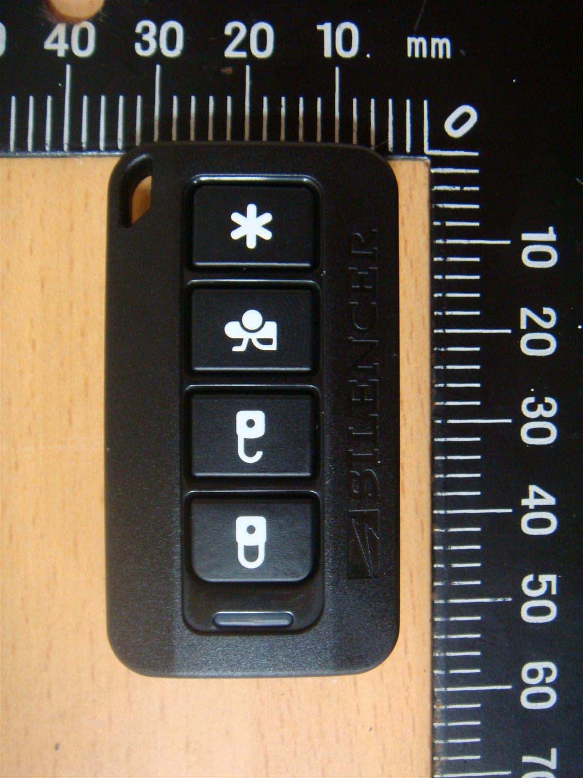
H5OT62
Dec 11, 2015Remote Control
Equipment Class
DSC - Part 15 Security/Remote Control Transmitter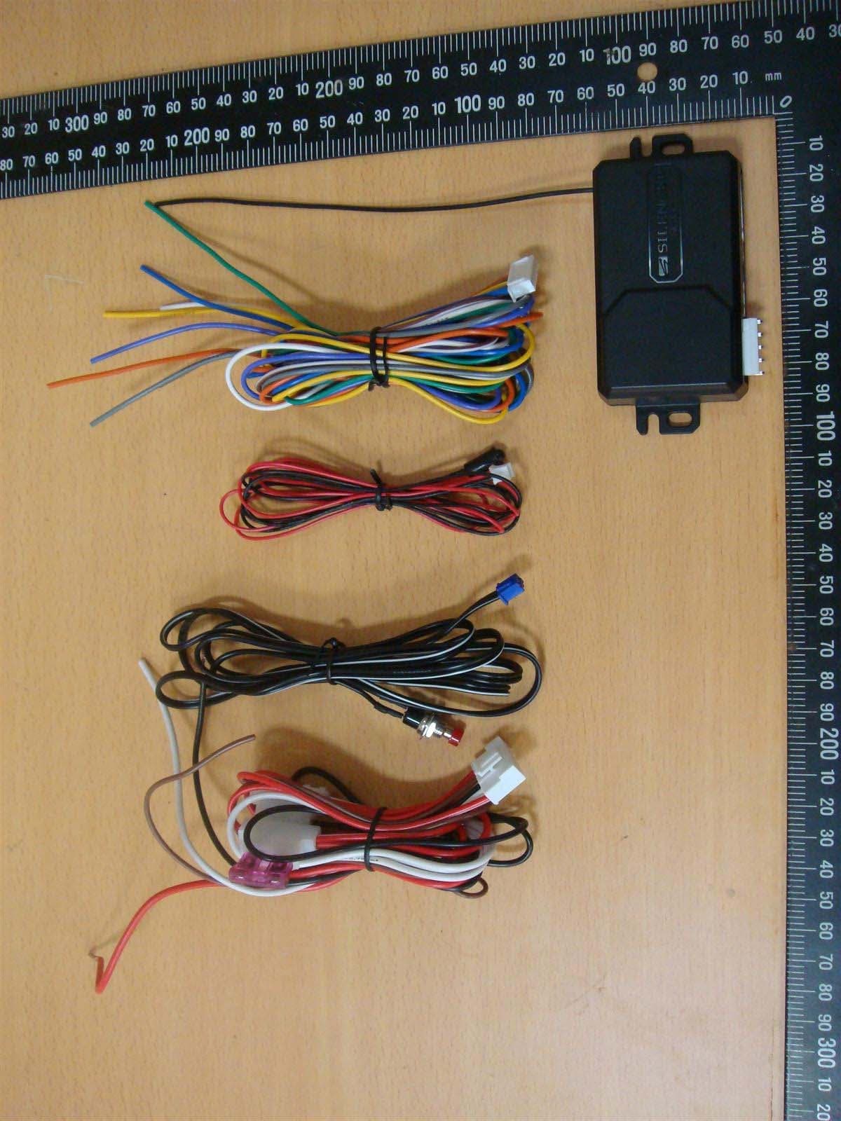
H5OR57
Dec 11, 2015Remote Control
Equipment Class
CYY - Communications Receiver used w/Pt 15 Transmitter
H5OTR64
Oct 22, 2015Remote Control
Equipment Class
DSS - Part 15 Spread Spectrum Transmitter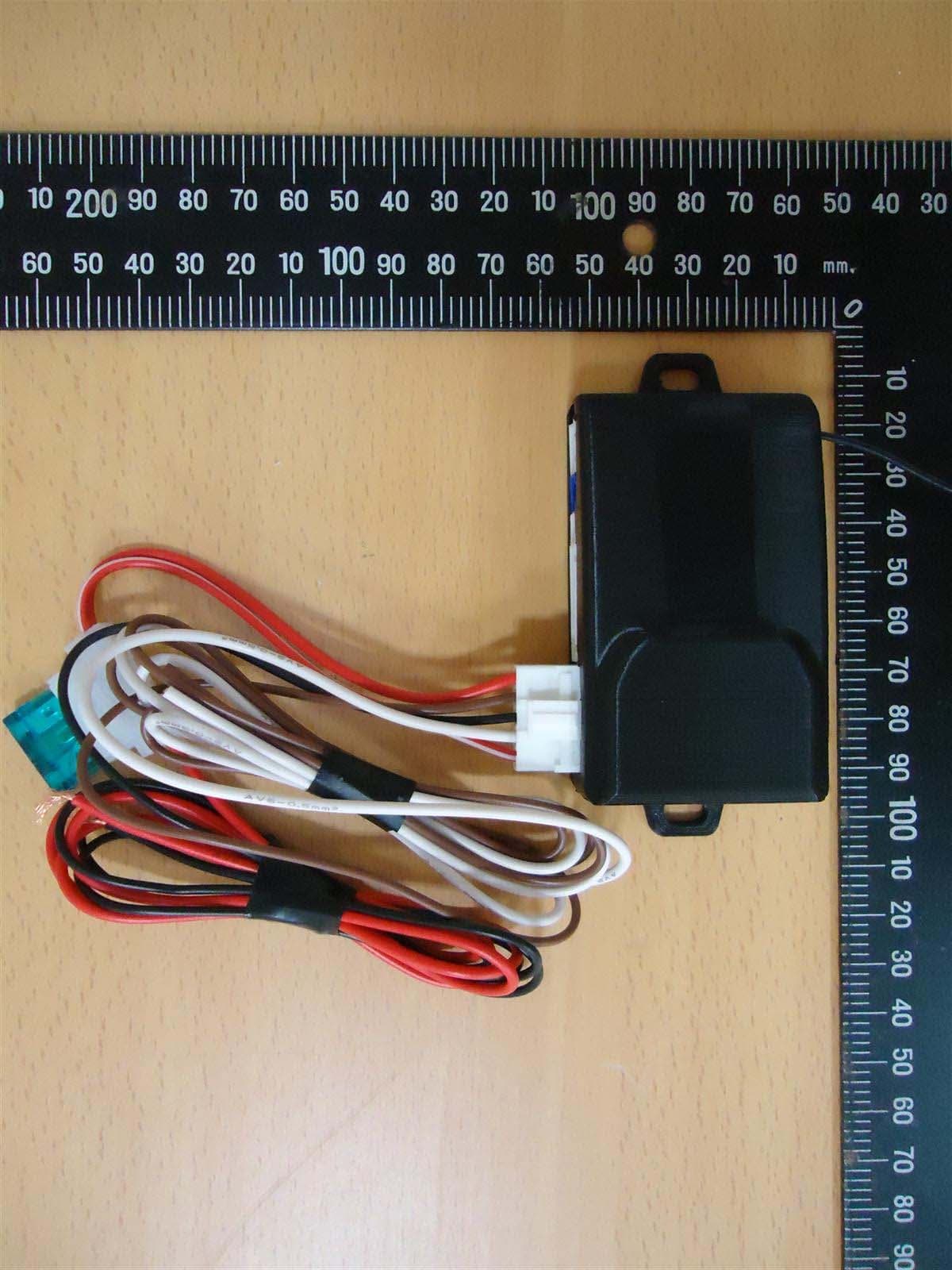
H5OR56
Sep 10, 2015Remote Control
Equipment Class
CYY - Communications Receiver used w/Pt 15 Transmitter
H5OT61
Sep 07, 2015Remote Control
Equipment Class
DSC - Part 15 Security/Remote Control Transmitter