H5OR44Car Alarm Receiver
Advance Security Inc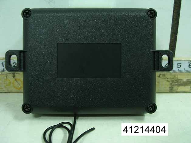
Click to zoom
Application Details
- Equipment Class
- CRR - Superregenerative Receiver
- Date of Grant
- Dec 30, 2004
- Application Purpose
- Original Equipment
- Date of Application
- Dec 30, 2004
- Equipment Note
- Car Alarm Receiver
- Frequency Range
- 433.92000000 - 433.92000000
- Company
- Advance Security Inc
- Country
- Taiwan
Documents & Files
Document Text
Text extracted from the exhibit documents filed with the FCC. Open a document above to read the original.
Users Manual
APRIL/18/2004 1 MKE - 400 14 PIN PLUG: 7. Black / White Wi r e: (-) 200mA Channel 3 Output 8. Yellow Wire: To Ignition Switched +12V 9. Red Wire: To Vehicle’s +12V Constant Power 2. White / Black Wire: (+) 10A Porch Light Relay Output 12. Green Wi re: (+) 200mA Vehicle’s Door Lock Output 13. Blue / White Wi re: (+) 200mA Cargo’s Door Unlock Output 11. Green / White Wi r e: (+) 200mA Vehicle’s Door Unlock Output 3. Brown Wire: (+) 10A Dome Light Relay Output 5. Violet Wire: (+) 200mA Channel 5 Output 6. Orange Wi re: (-) 200mA Channel 4 Output 14. Blue Wi re: (+) 200mA Cargo’s Door Lock Output 4. Whi te Wi re: (+) 10A Parking Light Relay Output 1 0. Red / White Wire: To RV’s +12V Constant Power 1. Black Wire: Ground to Vehicle Frame. APRIL/18/2004 2 PROGRAMMING A. 3- BUTTON TRANSMITTER PROGRAMMING: Note: This mode will only retain the last 4 remote transmitters programmed. If the transmitter memory is exceeded, the security system will start deleting transmitters from memory in chronological order. 1. Turn the Ignition 'switch to ‘ON’ position. Within 15 seconds. 2. Push the Program switch 3 times, the on board LED will flashing and the beeper will emit a long chirp to indicate the system in the Transmitter programming mode. 3. Press and hold any button of the transmitter until the on board LED turns On for 2 seconds and the beeper responds with a confirming chirp, indicating the signal has been stored into memory. 4. If you have additional transmitters (up to 4) that need to be programmed, repeat step 3 for each transmitter. Exit: Turn Ignition to 'OFF' position, or leave it for 15 seconds. The on board LED turns Off and the beeper will emit 3 long chirps to confirm exit. B. 4- BUTTON TRANSMITTERS PROGRAMMING: Note: This mode will only retain the last 4 remote transmitters programmed. If the transmitter memory is exceeded, the security system will start deleting transmitters from memory in chronological order. 1. Turn the Ignition 'switch to ‘ON’ position. Within 15 seconds. 2. Push the Program switch 5 times, the on board LED will flashing and the beeper will emit a long chirp to indicate the system in the Transmitter programming mode. 3. Press and hold any button of the transmitter until the on board LED turns On for 2 seconds and the beeper responds with a confirming chirp, indicating the signal has been stored into memory. 4. If you have additional transmitters (up to 4) that need to be programmed, repeat step 3 for each transmitter. Exit: Turn Ignition to 'OFF' position, or leave it for 15 seconds. The on board LED turns Off and the beeper will emit 3 long chirps to confirm exit. C. FEATURES PROGRAMMING: 1. Turn the Ignition 'switch to ‘OFF’ position. Within 15 seconds. 2. Push the Program switch 7 times, the on board LED wills Turns On constantly and the beeper will emit a long chirp to indicate the system in the Feature programming mode. 3. Press and release the transmitter button ‘A’ corresponding to the feature ‘A’ you want to change. - The beeps from beeper and the on board LED pause will indicate previously setting. 4. Depress the transmitter button ‘A’ again to change the feature again. Simple keep re-depressing the transmitter button ‘A’ again until the module advances to your desired setting. 5. Depress the transmitter button ‘B’ corresponding to the feature ‘B’ you wants to program. Press Transmitter Button or keypad One Beep / LED one pause Factory Default Setting Two Beeps / LED Two pauses Press Button on the transmitter or Press and hold the “ 1/2 ” Key on the keypad for 3 seconds Channel 3 Output = Momentary output Channel 3 Output = Latched output Press Button on the transmitter or Press and hold the “ 3/4 ” Key on the keypad for 3 seconds Channel 4 Output = Momentary output Channel 4 Output = Latched output Press Button on the 3 button transmitter or Press Button on the 4 button transmitter or Press and hold the “ 5/6 ” Key on the keypad for 3 seconds Channel 5 Output = Momentary output Channel 5 Output = Latched output Exit: Turn Ignition to 'ON' position or Press the “LOCK” button 1 seconds on the key pad or leave it for 15 seconds. The beeper will emit 3 long chirps and the on board led will turns Off to confirm exit. APRIL/18/2004 3 D. ALL CODES BACK TO DEFAULT: 1 Enter the “MAGNADYNE Master Code” (7352000) on the keypad; the beeper will emit a long chirp to confirm the correct code was entered. 2 Press the “LOCK” key on the keypad and holding in for 5 seconds until five beeps is hearing then release the “LOCK” key 3 The system will re-program all codes back to default. (Default dealer code is 12345 and user code is 54321) E. RE-PROGRAM THE DEALER CODE: Default Dealer Code is 12345 1. Enter the “Dealer Code” on the keypad; the beeper will emit a long chirp to confirm the correct code was entered. 2. Press the “LOCK” key on the keypad and holding in for 2 seconds until five beeps is hearing then release the “LOCK” key. 3. Enter the new 4 – 6 digit dealer codes on the keypad. (The dealer code can be 4, 5 or 6 digits.) 4. Finish by press the “LOCK” key on the keypad one long beep with 2 short beeps to confirm the new dealer code has been stored into memory and the all user code was back to default setting (Default user code is 54321). Exit: If 15 seconds of inactivity expire during of above steps, the unit will revert back to the last successfully stored code. 3 long beep to confirm exit. F. PROGRAM THE USER CODE: Default Dealer Code is 54321 Note: This mode will only retain the last 4 “user code” programmed. If the “user code” memory is exceeded, the system will start deleting “user code” from memory in chronological order. 1. Enter the “Dealer Code” on the keypad; the beeper will emit a long chirp to confirm the correct code was entered. 2. Enter the new 4 – 6 digit user codes on the keypad. (The user code can be 4, 5 or 6 digits.) 3. Finish by press the “LOCK” key on the keypad one long beep with 2 short beeps to confirm the new dealer code has been stored into m…
Text truncated - open the document above for the full version.
Block Diagram
1 2 3 4 5 6 78 ABCD 8 7 6 5 4 3 2 1 D CBA Title Number Revision Size A3 Date: 14-Dec-2004 Sheet of File: E:\TEMP\Test.ddb Drawn By: 4MHz C18,L1,C22 ** MKE-40BK.S01 CH#3 OUTPUT CH#3 O/P DRV. U6:B,R29 D/L DRIVER R20,R21,Q9,Q11 D/L +/- OUTPUT U6:G,K4 D/HT O/P DRV. D/HT OUTPUT MKE-400 R34,R35,R36 SW. DETECTOR VALET SW INPUTIGNITION INPUT LED- OUTPUT LED+ OUTPUT PORCH OUTPUT CH#4 OUTPUT PARKING LIGHT OUT PARKING LIGHT INCH#5 OUTPUT CARGO +/- OUTPUT DATA O/P AMP U2 RF IC MATCHING IMPEDANCE R28,R29 SW. DETECTOR U5 CODE MEMORY LED O/P DRV.R10,U6:F PORCH O/P DRV U6:A,K2 CH#4 O/P DRV. U6:D,R30 P/L O/P DRV. U6:C,K3 CH#5 O/P DRV. U6:E,R31 R1,R2,Q4,Q6CARGO DRIVER VOLTAGE REGULATORD5,D6,R24,C19,C20 U1,R32,R33,C32POWER ON RESET +12V INPUT BLOCK DIAGRAM 01 INC. ADVANCED SECCURITY 1 FLOWER 1 DATA O/P DRV. R7,Q3,R8 KEYPAD DATA OUTPUT CODE DETECTOR C10,R11 DATA INPUT
External Photos
Compliance Certification Services Inc. Report No: 41214404 Date of Issue: December 23, 2004 Page PHOTOGRAPHS OF EUT
ID Label/Location Info
FCC ID LABEL FORMAT AND LOCATION Advance Security Inc. FCC ID: H5OR44 FCC ID: H5OR44 This device complies with part 15 of the FCC Rules. Operation is subject to the following two conditions: (1) This device may not cause harmful interference, and (2) this device must accept any interference received, including interference that may cause undesired operation. FCC ID LABEL AREA
Internal Photos
Compliance Certification Services Inc. Report No: 41214404 Date of Issue: December 23, 2004 Page Compliance Certification Services Inc. Report No: 41214404 Date of Issue: December 23, 2004 Page
Operational Description
(MKE-400) Operational Description The radio frequency car-alarm is a system that it controllers locking(arm) and unlocking(disarm) the door of vehicle by wireless remote controller. This system consists of transmitter and receiver. The receiver (EUT) is fixed inside the vehicle and powered 12V from car battery. It works intermittently to prevent the battery exhaustion and check the vehicle status. It is designed to operate on a single fixed frequency 433.92 MHz by frequency modulation. It runs continuously to receive the signals completely, when the receiving module in receiver detects several synchronous codes, unique identification code, security code and function code transmitted from transmitter. After receiving the signal, the 8bit CPU in receiver decides which operation will be performed. And then driving circuit in receiver performs selected operations by pressing the button of the remote transmitter. All tuning and verification are performed by the manufacturer and there are no adjustments which can be made by the user. External ground is the chassis of vehicle and receiving antenna is fixed on enclosure of the receiver.
Schematics
1 2 3 4 5 6 78 ABCD 8 7 6 5 4 3 2 1 D CBA Title Number Revision Size A3 Date: 14-Dec-2004 Sheet of File: E:\TEMP\Test.ddb Drawn By: +12VB +12VB +12VB S2 VALET +5V R36 330K R354K7 R34 4K7 C33 223 +5V R331K C32104 R3247K V+ V R R G G U1 HT-7039A R31 10R 1/2W R29 10R 1/2W R30 10R 1/2W C31104 R27 100K R2610K +5V 9 W2I CARGO-D/UL 2 15 U6B2003 4 13 89 U6D2003 10 W2J RV-BAT 7 W2G P/L 12 W2L D/L 8 W2HPORCH R25 1R 1/2W ZD224V C30 100uF R24 47R 1/4W VZ2 180K X2 4MHz C29104 C26104 C28104 C20 10uF C19 470uF D61N4003 VI I GND G VO O U4 HT-7551 CS 1 CLK 2 DI 3 DO 4 VSS 5 ORG 6 MU 7 VCC 8 U5 93LC46 R2333K C17223 C16104 2 W2B D/UL B+ 1 W2A CARGO-D/L 3 W2C CH#3 5 W2E IGN 6 W2F CH#5 +5V 11 W2K CH#4 13 W2M D/HT 14 W2N +12V(BAT) B+ K3 12V/15A D4 1N4003 4 W2D GND D51N4003 R11 10K C10102 1 W3A DATA O/P 2 W3B DATA I/P 3 W3C GND 4 W3D B+ B+ B+ R104K7 Q3 D471 R8 10K +5V R7 10K C8223 VZ3 180K +12V +12V D3 1N4003 K4 12V/15A B+ B+ K2 12V/15A D2 1N4003 L2 RED LED C639P C439P 3 14 U6C2003 6 11 U6F2003 5 12 U6E2003 R2 2K2 R1 2K2 Q4 B564 R6 47K R22 2K2 Q5 D471 Q6 D471 D7 1N4003 R122K2 R1347K Q7 B564 D8 1N4003 D9 1N4003 D10 1N4003 B+ R143R3 1/2W R153R3 1/2W B+ D11 1N4003 D12 1N4003 D13 1N4003 Q9 B564 R1647K R172K2 D14 1N4003 Q10 D471 Q11 D471 R18 2K2 R19 47K Q13 B564 R202K2 R212K2 PB3 7 PA0 6 PA1 5 PB1 9 PB0 10 PC0 13 PA6 20 PB2 8 VSS 11 OSC2 18 PB6 24 PB7 23 PA4 22 PA2 4 INT 12 OSC1 17 PA5 21 PB5 1 PB4 2 PA3 3 PC2 14 PA7 19 RES 15 VDD 16 U3 HT-48R30A 7 10 U6G2003 116U6A 2003 * ** RF MODE RF I/P DATA I/P P/L IGN D/HT DU/L 2 D/L 2 PORCH CH#4CH#5CH#3 ** MKE-40L1.S01 1 1 FLOWER ADVANCE SECURITY INC MKE-100/300/400 D/L CSCKDIO VALET DATA O/P DU/L FEQ:434MHz 001 * * * GND LED * ** D/L+/- O/P,CH#5 - 1 2 3 4 ABCD 4 3 2 1 D CBA Title Number Revision Size A4 Date: 14-Dec-2004 Sheet of File: E:\TEMP\Test.ddb Drawn By: 3 W1C GND 2 W1B +5V 1 W1A DATA R5 10K R3 120K R4 180K C15203 C27470P R9 100K C25220P C21103 L1 15nH C224P7 C5 100P C7 104 X1 13.225MHz C14 8P C1322P C118P2 C2333P C9 473 C126P8 C3 100P C2 100P FL1 10.7MHz L6 10nH CRST1 1 VCC 2 LNI 3 TAGC 4 AGND 5 LNO 6 VCC 7 MI 8 MIX 9 SLN 20 OPP 21 FFB 22 THRES 23 3VOUT 24 DATA 25 PDO 26 PDWN 27 CRST2 28 AGND 10 SLP 19 FSEL 11 IFO 12 DGND 13 VDD 14 LF 15 CSEL 16 LIM 17 LIMX 18 U2 TDA5200 +5V C24 0.47uF C182P ANT 500mm ** MKE-RF.S01 F:434MHz 001 MKE-RF ADVANCE SECURITY INC. FLOWER * ** *
Test Report
Compliance Certification Services Inc. Report No: 41214404-PR1 FCC ID: H5OR44 Date of Issue: December 23, 2004 Page 1 FCC 47 CFR PART 15 SUBPART B TEST REPORT For Car Alarm Receiver Model: MKE-400 Trade Name: Advance Security Inc. Issued to Advance Security Inc. 3F, 48 Ta An Street, Hsi Chih, Taipei Hsien, TAIWAN R.O.C. Issued by Compliance Certification Services Inc. Hsintien Lab. No. 165, Chunghsen Road, Hsintien City Taipei Hsien, Taiwan TEL: (02) 2217-0894 FAX: (02) 2217-1029 Note: This report shall not be reproduced except in full, without the written approval of Compliance Certification Services Inc. Ltd. This document may be altered or revised by Compliance Certification Services Inc. personnel only, and shall be noted in the revision section of the document. Compliance Certification Services Inc. Report No: 41214404-PR1 FCC ID: H5OR44 Date of Issue: December 23, 2004 Page TABLE OF CONTENTS 1 TEST RESULT CERTIFICATION..................................................................... 3 2 EUT DESCRIPTION............................................................................................. 4 3 TEST METHODOLOGY ..................................................................................... 5 3.1 EUT SYSTEM OPERATION ........................................................................ 5 3.2 DECISION OF FINAL TEST MODE........................................................... 5 4 SETUP OF EQUIPMENT UNDER TEST .......................................................... 6 5 FACILITIES AND ACCREDITATIONS ........................................................... 7 5.1 FACILITIES .................................................................................................... 7 5.2 LABORATORY ACCREDITATIONS AND LISTINGS ............................ 7 6 INSTRUMENT AND CALIBRATION ............................................................... 8 6.1 MEASURING INSTRUMENT CALIBRATION ........................................ 8 6.2 TEST AND MEASUREMENT EQUIPMENT ............................................ 8 7 LINE CONDUCTED & RADIATED EMISSION TEST .................................. 9 7.1 LIMIT............................................................................................................... 9 7.2 TEST PROCEDURE OF LINE CONDUCTED EMISSION ................... 10 7.3 TEST PROCEDURE OF RADIATED EMISSION................................... 12 7.4 TEST RESULTS ............................................................................................ 14 APPENDIX I - PHOTOGRAPHS OF TEST SETUP ........................................... 16 APPENDIX II - TEST RESULT OF FINAL DATAS........................................... 17 Compliance Certification Services Inc. Report No: 41214404-PR1 FCC ID: H5OR44 Date of Issue: December 23, 2004 Page 1 TEST RESULT CERTIFICATION Applicant: Advance Security Inc. 3F, 48 Ta An Street, Hsi Chih, Taipei Hsien, TAIWAN R.O.C. Manufacturer: Advance Security Inc. 3F, 48 Ta An Street, Hsi Chih, Taipei Hsien, TAIWAN R.O.C. Equipment Under Test: Car Alarm Receiver Trade Name: Advance Security Inc. Model: MKE-400 Detailed EUT Description: See Item 2 of this report Date of Test: December 21, 2004 Applicable Standard Class / Limit Te s t R e s u l t FCC Part 15 Subpart B Class B No non-compliance noted Deviation from Applicable Standard None The above equipment was tested by Compliance Certification Services Inc. for compliance with the requirements set forth in the FCC Rules and Regulations Part 15, Subpart B and the measurement procedures were according to ANSI C63.4. This said equipment in the configuration described in this report shows the maximum emission levels emanating from equipment are within the compliance requirements. Approved by: Reviewed by: Compliance Certification Services Inc. Report No: 41214404-PR1 FCC ID: H5OR44 Date of Issue: December 23, 2004 Page 2 EUT DESCRIPTION Product Car Alarm Receiver Trade Name Advance Security Inc. Model MKE-400 Housing Type Plastic EUT Power Rating 12VDC from DC Power OSC/Clock Frequencies 13.225MHz; 10.7MHz; 4MHz Receiver Frequency 433.92MHz Number of Channels 1 Channel Operating Mode Point-to-Point Antenna Type Internal loop, which is built in EUT Note: The product is a composite system includes Transmitter and Receiver. This submittal(s) (test report) is intended for FCC ID: H5OR44 filing to comply with FCC Part 15 Subpart B Rules. The composite system (Transmitter) is intended for FCC ID: H5OT21 is compliance with FCC Part 15 Subpart C Rules. I/O PORT OF EUT I/O Port Type Q’TY TESTED WITH Note: Client consigns only one model sample (Model Number is MKE-400) to test. Compliance Certification Services Inc. Report No: 41214404-PR1 FCC ID: H5OR44 Date of Issue: December 23, 2004 Page 3 TEST METHODOLOGY 3.1 EUT SYSTEM OPERATION 1. Turn on the EUT by connect to DC power supply. 2. EUT receive the data from transmitter by pressing and hold the button. Note: Test program is self-repeating throughout the test. 3.2 DECISION OF FINAL TEST MODE 1. The following test mode(s) were scanned during the preliminary test: Mode: 1. NORMAL MODE 2. After the preliminary scan, the following test mode was found to produce the highest emission level. Radiation: Mode 1 Then, the EUT configuration and cable configuration of the above highest emission mode was recorded for all final test items. Compliance Certification Services Inc. Report No: 41214404-PR1 FCC ID: H5OR44 Date of Issue: December 23, 2004 Page 4 SETUP OF EQUIPMENT UNDER TEST Setup Diagram See test photographs attached in Appendix I for the actual connections between EUT and support equipment. Support Equipment No Device Ty pe Model Serial No. FCC ID/ BSMI ID Brand Data Cable Power Cord 1. DC Power Supply PS140YA N/A N/A DAIWA Unshielded, 0.4m Unshielded, 1.8m Note: All the above equipment/cables were placed in worse case positions to maximize emission signals during emission test. Grounding: Grounding was in accordance with the manufacturer’s requiremen…
Text truncated - open the document above for the full version.
Test Setup Photos
Compliance Certification Services Inc. Report No: 41214404-PR1 FCC ID: H5OR44 Date of Issue: December 23, 2004 Page APPENDIX I - PHOTOGRAPHS OF TEST SETUP RADIATED EMISSION TEST
Contact Information
Applicant
Michael Chen(SAL)
Test Firm
Compliance Certification Services Inc.Kurt Chen
Technical Specifications
| # | Rule Parts | Frequency Range | Power Output |
|---|---|---|---|
| 1 | 15B | 433.92 MHz - 433.92 MHz | - |
Other Applications from Advance Security Inc
H5OT62
Dec 11, 2015Remote Control
Equipment Class
DSC - Part 15 Security/Remote Control Transmitter
H5OR57
Dec 11, 2015Remote Control
Equipment Class
CYY - Communications Receiver used w/Pt 15 Transmitter
H5OTR64
Oct 22, 2015Remote Control
Equipment Class
DSS - Part 15 Spread Spectrum Transmitter
H5OR56
Sep 10, 2015Remote Control
Equipment Class
CYY - Communications Receiver used w/Pt 15 Transmitter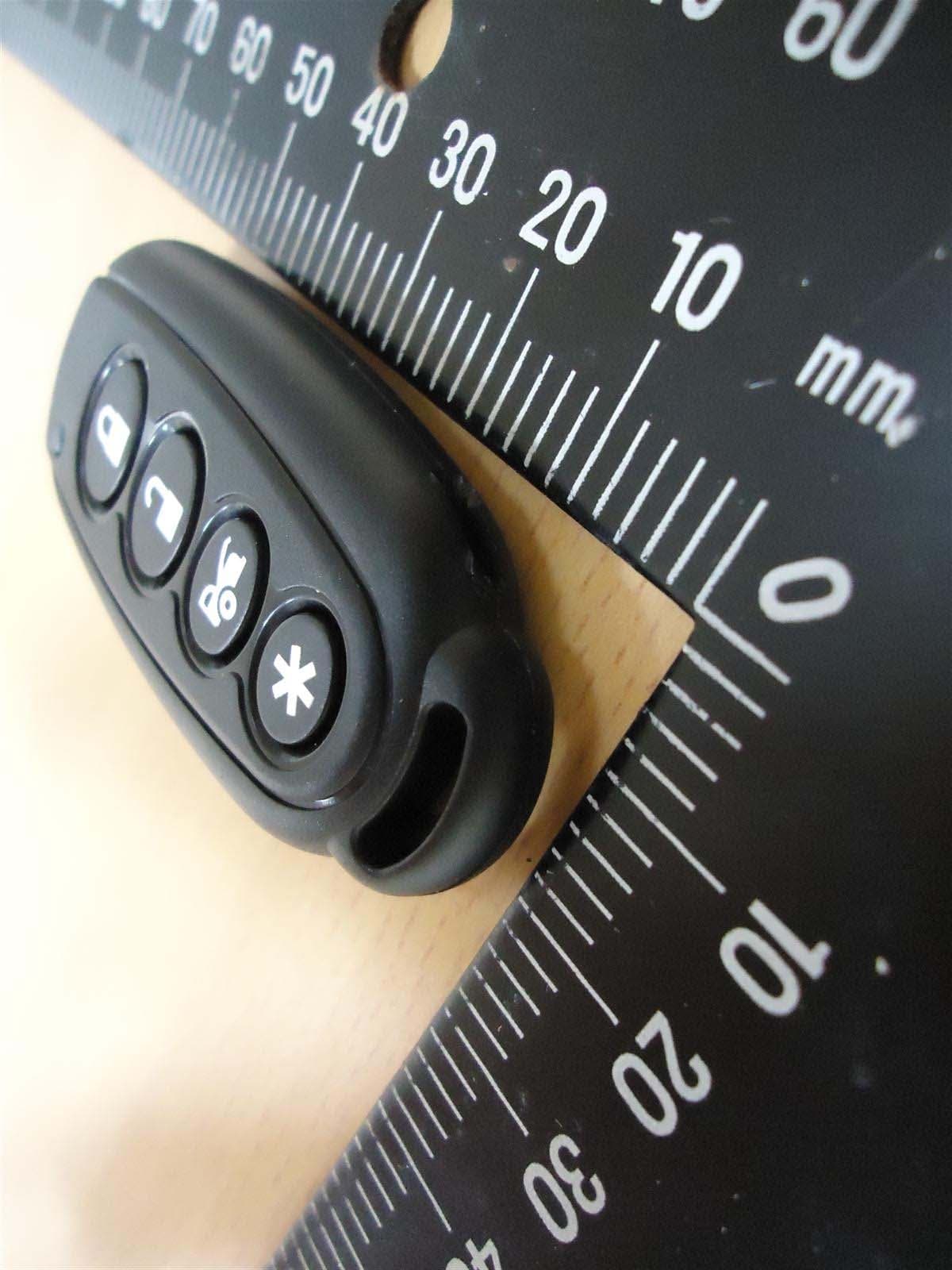
H5OT61
Sep 07, 2015Remote Control
Equipment Class
DSC - Part 15 Security/Remote Control Transmitter