H5OR47Car Alarm Receiver
Advance Security Inc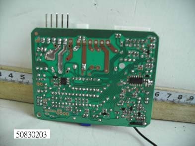
Click to zoom
Application Details
- Equipment Class
- CYY - Communications Receiver used w/Pt 15 Transmitter
- Date of Grant
- Sep 08, 2005
- Application Purpose
- Original Equipment
- Date of Application
- Sep 08, 2005
- Equipment Note
- Car Alarm Receiver
- Frequency Range
- 433.92000000 - 433.92000000
- Company
- Advance Security Inc
- Country
- Taiwan
Documents & Files
Document Text
Text extracted from the exhibit documents filed with the FCC. Open a document above to read the original.
Users Manual
JULY/04/2005 ALA225 1 MODEL ALA225 REMOTE CONTROL AUTO ALARM SYSTEM INSTALLATION & OPERATION INSTRUCTIONS WIRING DIAGRAM Main 5 Pin White harness 6 Pin White Mini Connector Black Antenna Wire LED Indicator Valet Switch Blue Wire: (-) 200mA Unlock Pulse Green Wire: (-) 200mA Lock Pulse 2 Pin Whi te 2 Pin Blue 2 Pin Whi te 5 Pin Whi te 6 Pin Whi te MAIN 5 PIN WIRE HARNESS: 5. Red Wire: +12V To Constant Battery Source 4. Brown Wire: Positive out put To Siren 3. Black Wire: Ground to Vehicle FRAME 2. White Wire: Parking Light Relay Output 1. Red / White Wire: Parking Light Relay Power Input 15A Fuse 6 PIN MINI CONNECTOR WIRE HARNESS: 6. Gray Wire: (-) 200mA Programmable Output 2. Blue Wire: Instant Trigger Ground Input 1. Violet Wire: Positive Door Pin Switch Input 4. Yellow Wire: To I gnition Switched + 12V 5. Orange Wire: 200mA Grounded when armed 3. Green Wire: Negative Door Pin Switch Input 85 86 30 87a Cut To start solenoidFrom ignition switch Red wire White wire Orange wire Channel 3 / 2 Step Door Unlock. 12V 12V Yellow wire A. PROGRAMMING TRANSMITTER: Note: This mode will only retain the last 4 remote transmitters programmed. If the transmitter memory is exceeded, the security system will start deleting transmitters from memory in chronological order. 1. Turn the Ignition 'switch ‘OFF/ON’ 3 TIMES and stay in ON position. Within 15 seconds. JULY/04/2005 ALA225 2 2. Push the Valet switch 3 times and holding in on 3rd push until a long chirp is hearing then release the valet switch. You are now in the Transmitter programming mode. 3. Press and hold any button of the transmitter until the siren responds with a confirming chirp, indicating the signal has been stored into memory. 4. If you have additional transmitters (up to 4) that need to be programmed, repeat step 3 for each transmitter. Exit: Turn Ignition to 'OFF' position, or leave it for 15 seconds. Three long chirps & Three parking light flashes to confirm exit. B. ALARM FEATURES PROGRAMMING: ALARM FEATURE “I” PRORAMMING: 1. Turn the Ignition 'switch ‘ON/OFF’ 3 TIMES and stay in OFF position. 2. Push the Valet switch 2 times and holding in on 2 nd push until one chirp with a long chirp is hearing then release the valet switch. You are now in the Alarm feature ‘I’ programming mode. 3. Press and release the transmitter button ‘A’ corresponding to the feature ‘A’ you want to change. a. The siren chirps and LED pause will indicate newly setting. b. The system would advance to [2] LED flash, [2] chirp. (The factory default setting is always [1] LED flash, [1] chirp.) 4. Depress the transmitter button ‘A’ again to change the feature again. Simple keep re-depressing the transmitter button ‘A’ again until the module advances to your desired setting. 5. Depress the transmitter button ‘B’ corresponding to the feature ‘B’ you want to program. Press Transmitter Button One Chirp / LED one pulse Factory Default Setting Two Chirps / LED two pulse 1 Chirps on Chirps off 2 Automatic Rearm On Automatic Rearm Off 3 + Instantly Door Ajar Warning. 45 seconds Delay Door Ajar error chirp. Exit: Turn Ignition to 'ON' position, or leave it for 15 seconds. Three long chirps to confirm exit. ALARM FEATURE “II” PRORAMMING: 1. Turn the Ignition 'switch ‘ON/OFF’ 3 TIMES and stay in OFF position. 2. Push the Valet switch 4 times and holding in on the 4 th push until two chirps with a long chirp is hearing then release the valet switch. You are now in the Alarm feature ‘II’ programming mode. 3. Press and release the transmitter button ‘A’ corresponding to the feature ‘A’ you want to program. Press Transmitter Button One Chirp / LED one pulse Factory Default Setting Two Chirps / LED two pulse Three Chirps / LED three pulse 1 0.9-second Door lock pulses. 3.0-second Door lock pulse. Double pulse unlock 2 Active arming Passive arming without passive door locking Passive arming with passive door locking. 3 + Ignition controlled door locks & unlocks Without ignition controlled door locks & unlocks Exit: Turn Ignition to 'ON' position, or leave it for 15 seconds. Three long chirps to confirm exit. ALARM FEATURE “III” PRORAMMING: 1. Turn the Ignition 'switch ‘ON/OFF’ 3 TIMES and stay in OFF position. 2. Push the Valet switch 6 times and holding in on the 6 th push until three chirps with a long chirp is hearing then release the valet switch. You are now in the Alarm feature ‘III’ programming mode. 3. Press and release the transmitter button ‘A’ corresponding to the feature ‘A’ you want to program. Press Transmitter Button One Chirp / LED one pulse Factory Default Setting Two Chirps / LED two pulse 1 Shock Sensor Program Mode 2 Gray Wire = Trunk (Channel 3) Output Gray Wire = Two Step Door Unlock Output 3 + Car Jacking Off Car Jacking On Exit: Turn Ignition to 'ON' position, or leave it for 15 seconds. Three long chirps to confirm exit. ADJEST AND TEST THE SENSITIVITY LEVEL OF THE SHOCK SENSOR JULY/04/2005 ALA225 3 1. Turn the Ignition 'switch ‘ON/OFF’ 3 TIMES and stay in OFF position. 2. Push the Valet switch 6 times and holding in on the 6th push until three chirps with a long chirp is hearing then release the valet switch. You are now in the Alarm feature ‘Shock Sensor’ programming mode. 3. Press and hold button for 2 seconds. One long siren chirp to indicates the unit is ready to accept adjustments of the shock sensor. 4. Press button on the transmitter once will decrease sensitivity level by one, each time an decrease is made the siren chirp will respond with [1] chirp, while 2 chirp indicates the minimum of sensitivity. 5. Press button on the transmitter once will increase sensitivity level by one, each time an increase is made the siren/horn chirp will respond with [1] chirp, while 2 chirp indicates the maximum of sensitivity. 6. Hit the bumper or strong metal part of the vehicle to test the threshold level of the sensor. a). Activate the warn-away (first stage the shock sensor), the siren will emit a short chirp. b). Activate the full alarm (second stage the shock …
Text truncated - open the document above for the full version.
Block Diagram
1 2 34 ABCD 4 3 2 1 D CBA 12V INPUT IGNITION DATA O/P PIN SW1DOOR SW OVERRIDE SW PARKING LIGHT ARM OUTPUT CHANNEL 3 OUTPUT LED OUTPUT SIREN O/PDOOR LOCK O/PDOOR UNLOCK O/P Title Size ORCAD ADate File Number Revision Sheet of Drawn By : 2005-4-29 E:\DDB\235R-1C.DDB
Cover Letter(s)
ADVANCED ADVANCE SECURITY INC. 3F, 48 Ta An Street, Hsi Chih, Phone : (886-2) 8648-1688 E-mail : [email protected] Taipei Hsien, TAIWAN R.O.C. Telexfax : (886-2) 8648-1689 Date: August 18, 2005 Compliance Certification Services Certification Division 561F Monterey Road Morgan Hill, CA 95037 To whom it may concern: We, the undersigned, hereby authorize the Testing Division of Compliance Engineering Services, Inc., d.b.a. Compliance Certification Services and hereafter referred to as CCS, to act on our behalf in all manners relating to application for equipment authorization, including signing of all documents relating to these matters. Any and all acts carried out by CCS on our behalf shall have the same effect as acts of our own. We, the undersigned, hereby certify that we are not subject to a denial of federal benefits, that includes FCC benefits, pursuant to Section 5301 of the Anti-Drug Abuse Act of 1988, 21 U.S.C. 853(a). In authorizing CCS Testing Division as our agent, we still recognize that we are responsible to: comply with the relevant provisions of the certification program; b) make all necessary arrangements for the conduct of the evaluation, including provision for examining documentation and access to all areas, records (including internal audit reports) and personnel for the purposes of evaluation (e.g. testing, inspection, assessment, surveillance, reassessment) and resolution of complaints; c) make claims regarding certification only in respect of the scope for which certification has been granted; d) do not use our product certification in such a manner as to bring the Certification Division into disrepute and not make any statement regarding our product certification which the Certification Division may consider misleading or unauthorized; e) upon suspension or cancellation of certification, discontinue use of all advertising matter that contains any reference thereto and return any certification documents as required by the Certification Division; f) use certification only to indicate the products are certified as being in conformity with specified standards; g) endeavor to ensure that no certificate or report nor any part thereof is used in a misleading manner; h) ensure that any reference to our product certification in communication media such as documents, brochures or advertising, complies with the requirements of the Certification Division; i) keep a record of all complaints made known to the us relating to the product’s compliance with requirements of the relevant standard and to make these records available to the Certification Division when requested; j) take appropriate action with respect to such complaints and any deficiencies found in products or services that affect compliance with the requirements for certification; k) document the actions taken. This authorization is valid until further written notice from the applicant. ADVANCE SECURITY INC. TED LIN SALES MANAGER REMARK: 1. This authorization letter will be sent along with your application when filing with the Certification Division. 2. Please follow the format and type it on company letterhead and send original to us.
External Photos
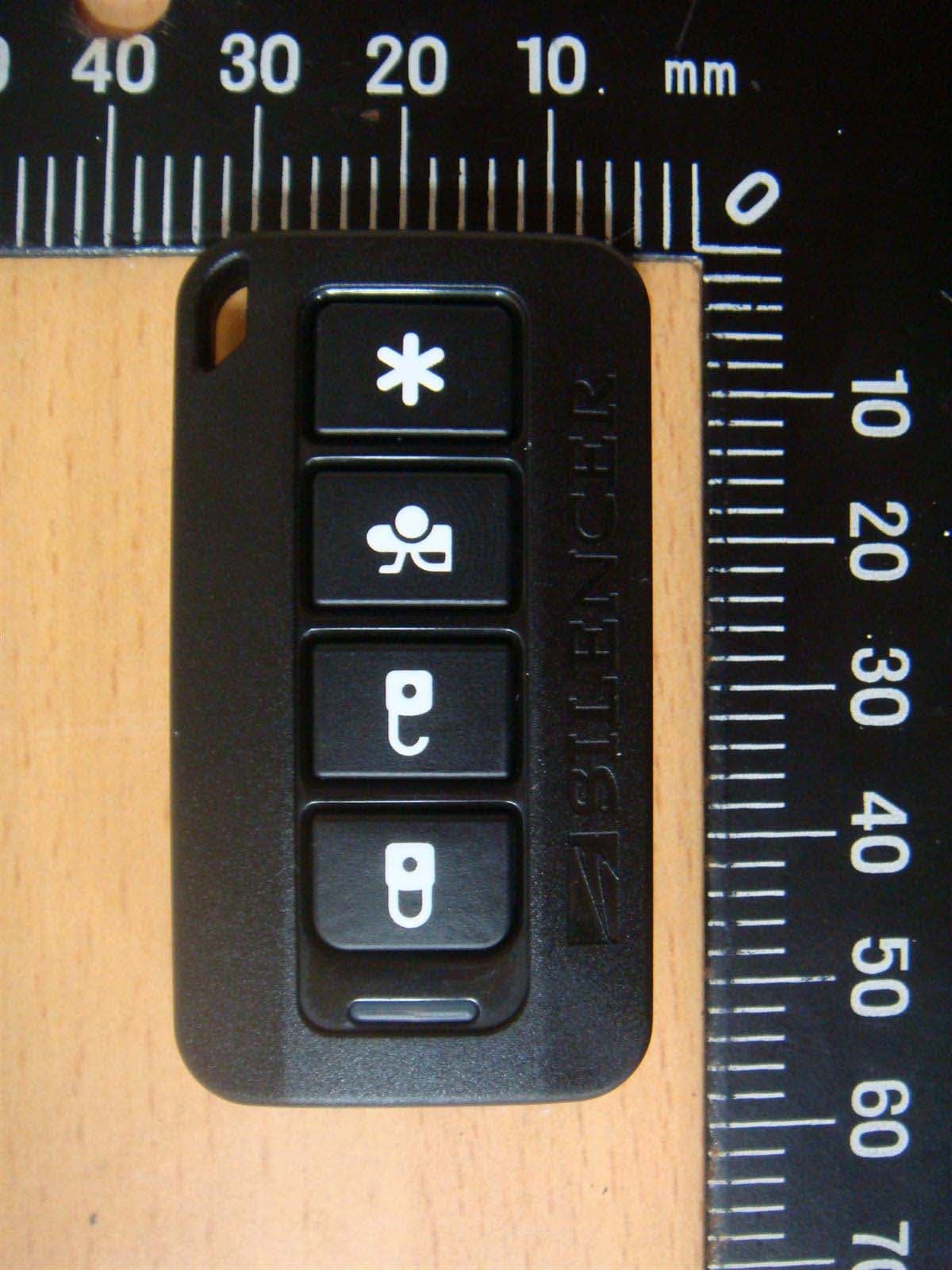
Compliance Certification Services Inc. Report No.: 50830203 Date of Issue: September 9, 2005 Page PHOTOGRAPHS OF EUT Compliance Certification Services Inc. Report No.: 50830203 Date of Issue: September 9, 2005 Page Compliance Certification Services Inc. Report No.: 50830203 Date of Issue: September 9, 2005 Page
ID Label/Location Info
FCC ID LABEL FORMAT AND LOCATION Advance Security Inc. FCC ID: H5OR47 FCC ID: H5OR47 This device complies with part 15 of the FCC Rules. Operation is subject to the following two conditions: (1) This device may not cause harmful interference, and (2) this device must accept any interference received, including interference that may cause undesired operation. FCC ID LABEL AREA
Internal Photos
Compliance Certification Services Inc. Report No.: 50830203 Date of Issue: September 9, 2005 Page Compliance Certification Services Inc. Report No.: 50830203 Date of Issue: September 9, 2005 Page Compliance Certification Services Inc. Report No.: 50830203 Date of Issue: September 9, 2005 Page Compliance Certification Services Inc. Report No.: 50830203 Date of Issue: September 9, 2005 Page Compliance Certification Services Inc. Report No.: 50830203 Date of Issue: September 9, 2005 Page
Operational Description
(ALA225) Operational Description The radio frequency car-alarm is a system that it controllers locking(arm) and unlocking(disarm) the door of vehicle by wireless remote controller. This system consists of transmitter and receiver. The receiver (EUT) is fixed inside the vehicle and powered 12V from car battery. It works intermittently to prevent the battery exhaustion and check the vehicle status. It is designed to operate on a single fixed frequency 433.92 MHz by frequency modulation. It runs continuously to receive the signals completely, when the receiving module in receiver detects several synchronous codes, unique identification code, security code and function code transmitted from transmitter. After receiving the signal, the 8bit CPU in receiver decides which operation will be performed. And then driving circuit in receiver performs selected operations by pressing the button of the remote transmitter. All tuning and verification are performed by the manufacturer and there are no adjustments which can be made by the user. External ground is the chassis of vehicle and receiving antenna is fixed on enclosure of the receiver.
Schematics
1 2 3 4 ABCD 4 3 2 1 D CBA 7 10 1 16 89 2 15 3 14 4 13 6 11 5 12 W1/4 W2/2 W2/1 W1/5 W3/1 W3/2 W6/2 W5/2 W6/3 W6/1 W1/6 +12V B+ 5V B+ 5V 5V 5V 5V 5V +12V B+ W5/1W4/2 5V CS 1 CK 2 DI 3 DO 4 GND 5 NC 6 NC 7 VDD 8 VI GND VO 32 1 114 56 7 123456 12 12 W1/5W1/4W1/3W1/2W1/1 W6/6W6/5W6/4W6/3 W2/2W2/1 W3/2W3/1 123456 W6/2W6/1 W6/5 B+ P0.1/INT1 1 VDD 2 P5.4 3 VSS 4 P0.0/INT0 5 P5.0 6 P5.1 7 P5.2 8 P5.3/BZ1/PWM1 9 P1.0 10 P1.1 11 P1.2 12 P1.3 13 P1.4 14 P1.5 15 P1.6 16 P1.7 17 P2.0 18 P2.1 19 P2.2 20 P2.3 21 P2.4 22 P2.5 23 P2.6 24 P2.7 25 XOUT/Fcpu 26 XIN 27 RST/VPP/P0.2 28 10 9 8 1213 14 5V 5V 5V Title Size 1520x1020Date File Number 2005-4-29 E:\DDB\235R-1C.DDB Revision Sheet of Drawn By : B+ W6/4 W6/6 B+ W1/2 W1/3 W1/6 12 B+ B+ POS POS POS POS POS 5V 5V B+ B+ 5V 5V TP1 TP1 U5/12 U5/12 U5/12 U5/7 U5/7 U5/7 U1/3 U1/3 U1/3 TP1
Test Report
Compliance Certification Services Inc. Report No.: 50830203-F FCC ID: H5OR47 Date of Issue: September 9, 2005 Page 1 FCC 47 CFR PART 15 SUBPART B TEST REPORT For CAR ALARM RECEIVER Model: ALA225 Trade Name: Advance Security Inc. Issued to Advance Security Inc. 3F, 48 Ta An Street, Hsi Chih, Taipei Hsien, TAIWAN R.O.C. Issued by Compliance Certification Services Inc. Hsintien Lab. No. 165, Chunghsen Road, Hsintien City Taipei Hsien, Taiwan TEL: (02) 2217-0894 FAX: (02) 2217-1029 Note: This report shall not be reproduced except in full, without the written approval of Compliance Certification Services Inc. Ltd. This document may be altered or revised by Compliance Certification Services Inc. personnel only, and shall be noted in the revision section of the document. Compliance Certification Services Inc. Report No.: 50830203-F FCC ID: H5OR47 Date of Issue: September 9, 2005 Page TABLE OF CONTENTS 1 TEST RESULT CERTIFICATION..................................................................... 3 2 EUT DESCRIPTION............................................................................................. 4 3 TEST METHODOLOGY ..................................................................................... 5 3.1 EUT SYSTEM OPERATION ........................................................................ 5 3.2 DECISION OF FINAL TEST MODE........................................................... 5 4 SETUP OF EQUIPMENT UNDER TEST .......................................................... 6 5 FACILITIES AND ACCREDITATIONS ........................................................... 7 5.1 FACILITIES .................................................................................................... 7 5.2 LABORATORY ACCREDITATIONS AND LISTINGS ............................ 7 6 INSTRUMENT AND CALIBRATION ............................................................... 8 6.1 MEASURING INSTRUMENT CALIBRATION ........................................ 8 6.2 TEST AND MEASUREMENT EQUIPMENT ............................................ 8 7 LINE CONDUCTED & RADIATED EMISSION TEST .................................. 9 7.1 LIMIT............................................................................................................... 9 7.2 TEST PROCEDURE OF LINE CONDUCTED EMISSION ................... 10 7.3 TEST PROCEDURE OF RADIATED EMISSION................................... 12 7.4 TEST RESULTS ............................................................................................ 14 APPENDIX I - PHOTOGRAPHS OF TEST SETUP ........................................... 16 APPENDIX II - TEST RESULT OF FINAL DATAS........................................... 17 Compliance Certification Services Inc. Report No.: 50830203-F FCC ID: H5OR47 Date of Issue: September 9, 2005 Page 1 TEST RESULT CERTIFICATION Applicant: Advance Security Inc. 3F, 48 Ta An Street, Hsi Chih, Taipei Hsien, TAIWAN R.O.C. Manufacturer: Advance Security Inc. 3F, 48 Ta An Street, Hsi Chih, Taipei Hsien, TAIWAN R.O.C. Equipment Under Test: CAR ALARM RECEIVER Trade Name: Advance Security Inc. Model: ALA225 Detailed EUT Description: See Item 2 of this report Date of Test: September 3, 2005 & September 5, 2005 Applicable Standard Class / Limit Te s t R e s u l t FCC Part 15 Subpart B, IC ICES-003 Class B No non-compliance noted Deviation from Applicable Standard None The above equipment was tested by Compliance Certification Services Inc. for compliance with the requirements set forth in the FCC Rules and Regulations Part 15, Subpart B and the measurement procedures were according to ANSI C63.4. This said equipment in the configuration described in this report shows the maximum emission levels emanating from equipment are within the compliance requirements. Approved by: Reviewed by: Compliance Certification Services Inc. Report No.: 50830203-F FCC ID: H5OR47 Date of Issue: September 9, 2005 Page 2 EUT DESCRIPTION Product CAR ALARM RECEIVER Trade Name Advance Security Inc. Model ALA225 Housing Type Plastic EUT Power Rating 12VDC from DC Power Supply OSC/Clock Frequencies 4MHz Receiver Frequency 433.92MHz Number of Channels 1 Channel Operating Mode Point-to-Point Antenna Type Internal loop, which is built in EUT Note: The product is a composite system includes Transmitter and Receiver. This submittal(s) (test report) is intended for FCC ID: H5OR47 filing to comply with FCC Part 15 Subpart B Rules. The composite system (Transmitter) is intended for FCC ID: H5OT30 is compliance with FCC Part 15 Subpart C Rules. I/O PORT OF EUT I/O Port Type Q’TY TESTED WITH Note: Client consigns only one model sample (Model Number is ALA225) to test. Compliance Certification Services Inc. Report No.: 50830203-F FCC ID: H5OR47 Date of Issue: September 9, 2005 Page 3 TEST METHODOLOGY 3.1 EUT SYSTEM OPERATION 1. Turn on the EUT by connect to DC power supply. 2. EUT receive the data from transmitter by pressing and hold the button. Note: Test program is self-repeating throughout the test. 3.2 DECISION OF FINAL TEST MODE 1. The following test mode(s) were scanned during the preliminary test: Mode: 1. NORMAL MODE 2. After the preliminary scan, the following test mode was found to produce the highest emission level. Radiation: Mode 1 Then, the EUT configuration and cable configuration of the above highest emission mode was recorded for all final test items. Compliance Certification Services Inc. Report No.: 50830203-F FCC ID: H5OR47 Date of Issue: September 9, 2005 Page 4 SETUP OF EQUIPMENT UNDER TEST Setup Diagram See test photographs attached in Appendix I for the actual connections between EUT and support equipment. Support Equipment No Device Ty pe Model Serial No. FCC ID/ BSMI ID Brand Data Cable Power Cord 1. DC Power Supply PS140YA N/A N/A DAIWA Unshielded, 0.9m X2 Unshielded, 1.8m Note: All the above equipment/cables were placed in worse case positions to maximize emission signals during emission test. Grounding: Grounding was in accordance with the manufacturer…
Text truncated - open the document above for the full version.
Test Setup Photos
Compliance Certification Services Inc. Report No.: 50830203-F FCC ID: H5OR47 Date of Issue: September 9, 2005 Page APPENDIX I - PHOTOGRAPHS OF TEST SETUP RADIATED EMISSION TEST
Contact Information
Applicant
Michael Chen(SAL)
Test Firm
Compliance Certification Services Inc.Kurt Chen
Technical Specifications
| # | Rule Parts | Frequency Range | Power Output |
|---|---|---|---|
| 1 | 15B | 433.92 MHz - 433.92 MHz | - |
Other Applications from Advance Security Inc
H5OT62
Dec 11, 2015Remote Control
Equipment Class
DSC - Part 15 Security/Remote Control Transmitter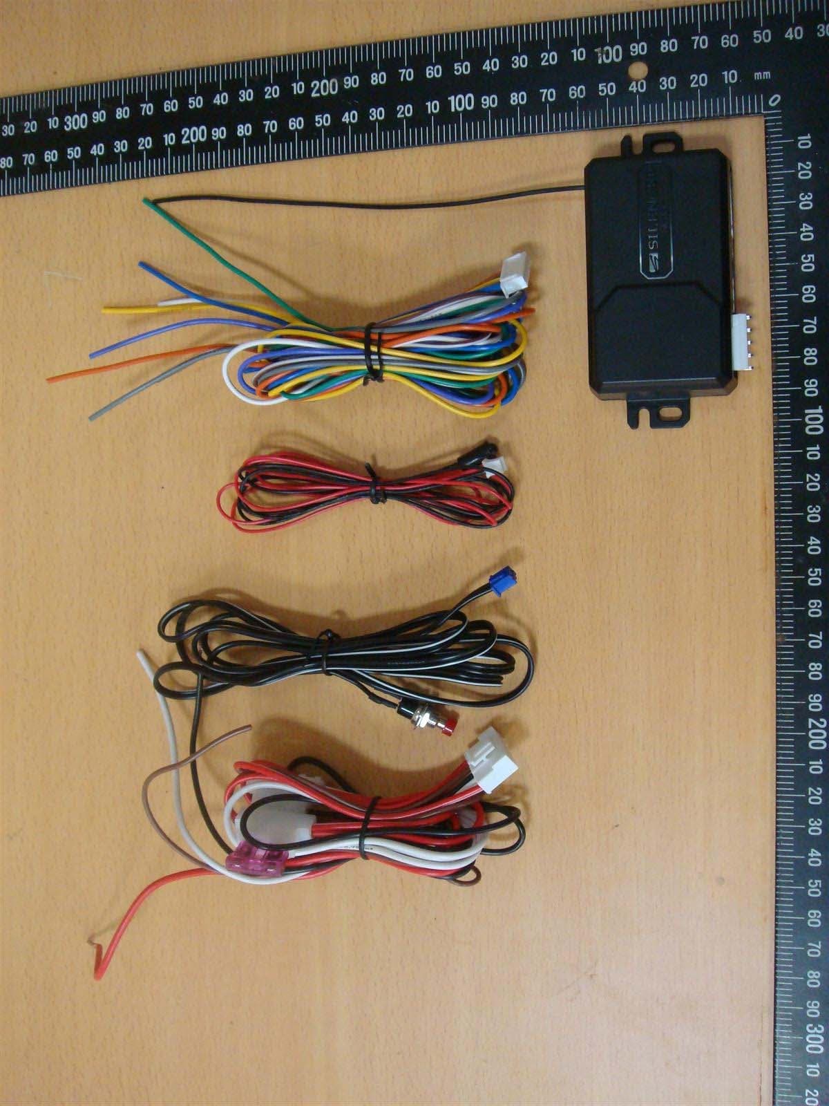
H5OR57
Dec 11, 2015Remote Control
Equipment Class
CYY - Communications Receiver used w/Pt 15 Transmitter
H5OTR64
Oct 22, 2015Remote Control
Equipment Class
DSS - Part 15 Spread Spectrum Transmitter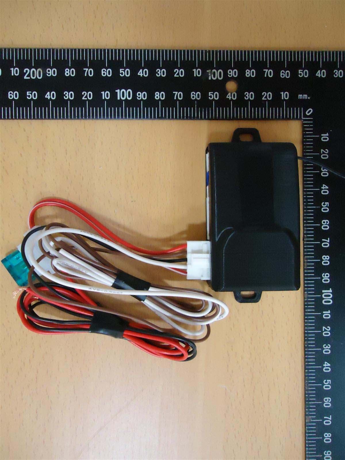
H5OR56
Sep 10, 2015Remote Control
Equipment Class
CYY - Communications Receiver used w/Pt 15 Transmitter
H5OT61
Sep 07, 2015Remote Control
Equipment Class
DSC - Part 15 Security/Remote Control Transmitter