H5OR54Car Alarm Receiver
Advance Security Inc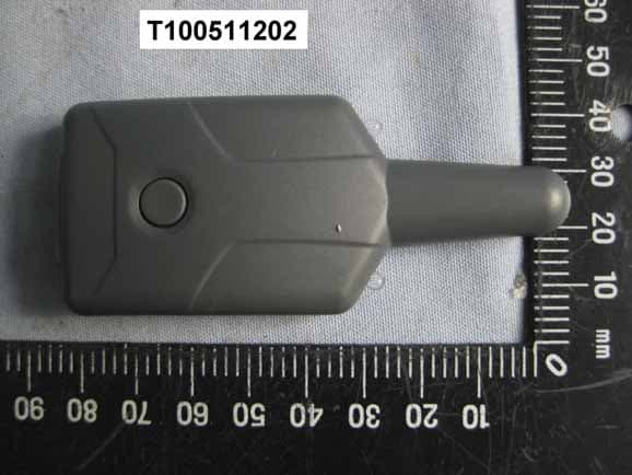
Click to zoom
Application Details
- Equipment Class
- CYY - Communications Receiver used w/Pt 15 Transmitter
- Date of Grant
- Jun 14, 2010
- Application Purpose
- Original Equipment
- Date of Application
- Jun 14, 2010
- Equipment Note
- Car Alarm Receiver
- Frequency Range
- 433.92000000 - 433.92000000
- Company
- Advance Security Inc
- Country
- Taiwan
Documents & Files
Document Text
Text extracted from the exhibit documents filed with the FCC. Open a document above to read the original.
Users Manual
12010 Audiovox Electronics Corporation. All rights reserved. PROFESSIONAL SERIES Remote Start with Keyless Entry Installation Guide CA6150RX 22010 Audiovox Electronics Corporation. All rights reserved. Before You Begin...................................................................................... 3 Wire Connection Guide........................................................................... 4 8 Pin Main Harness................................................................................... 5 3 Pin Parking Light Harness..................................................................... 8 6 Pin Start Harness................................................................................... 8 4 Pin Auxiliary Harness.......................................................................... 10 2 Pin Door Lock Output Harness........................................................... 11 Additional Ports...................................................................................... 15 Antenna / LED / Programming Port....................................................... 15 DBI Port .................................................................................................... 15 Tracking Port........................................................................................... 15 Set Up & Programming.......................................................................... 16 Transmitter Programming........................................................................ 16 Manual Feature Programming................................................................. 16 Programming Feature Banks.................................................................. 17 Tach Programming.................................................................................. 18 Smart Tachless.Mode............................................................................. 18 Feature Descriptions............................................................................. 19 Transmitter Button Functions............................................................. 22 Remote Start Shutdown Diagnostics................................................ 23 System Layout......................................................................................... 24 Table of Contents 32010 Audiovox Electronics Corporation. All rights reserved. PROFESSIONAL INSTALLATION STRONGLY RECOMMENDED Installation Precautions: Roll down window to avoid locking keys in vehicle during installation Avoid mounting components or routing wires near hot surfaces Avoid mounting components or routing wires near moving parts Tape or loom wires under hood for protection and appearance Technical Support (800) 421-3209 or go to http://techservices.codesystems.com Use a Digital Multi Meter for testing and verifying circuits. DO NOT USE A TEST LIGHT, OR "COMPUTER SAFE PROBE" as these can set off air bags or damage vehicle computers. Use grommets when routing wires through metal surfaces BEFORE YOU BEGIN 42010 Audiovox Electronics Corporation. All rights reserved. 6 Pin Start Harness 4 Pin Auxiliary Output Harness 8 Pin Main Harness 3 Pin Parking Light Harness 52010 Audiovox Electronics Corporation. All rights reserved. 2 Pin Lock Output Harness 1VIOLET/BLACKAUX 1 This wire provides a ( - ) 500mA output capable of driving relays. For Control of optional accessories (i.e. Power Window/Sunroof, etc.). To activate refer to the transmitter button configuration chart. Please refer to the selectable options for timing. 8 Pin Main Harness 2BLACK/WHITEILLUMINATED ENTRY OUTPUT ( - ) This wire provides a ( - ) 500mA output for 30 seconds when the system is disarmed capable of driving relays. Locate the vehicle’s dome light or pin switch wire. Verification: This wire will register positive voltage or ground when the vehicle's dome light is turned ON. 3BROWN/BLACKHORN OUTPUT ( - ) Locate the vehicle’s horn wire. Verification: This wire will register at positive voltage and register ground when the horn switch is pressed. Connect the BROWN/BLACK wire to the vehicle’s horn wire. This is a low current output, 500mA. 62010 Audiovox Electronics Corporation. All rights reserved. Fused +12 Volt Battery Source 30 87 87a 86 85 BLUE/BLACK ActiveOutput Wire VATS Control Module Matching Value Resistor Ignition Switch VATS Wire #1, WHITE or WHITE/BLACK VATS Wire #2, WHITE or VIOLET/WHITE X CUT GM VATS Fused +12 Volt Battery Source 30 87 87a 86 85 BLUE/BLACK Active Outpu t Wire To Vehicle's 2nd or 3rd Ignition Wire Jump To PINK Ignition Output Wire From Control Module Ignition 3Accessory 2/ 3 Fused +12 Volt Battery Source 30 87 87a 86 85 BLUE/BLACK Active Outpu t Wire To Vehicle's 2nd or 3rd Accessory Wire Jump To ORANGE Accessory Output Wire From Control Module 4RED/WHITETRUNK RELEASE OUTPUT ( - ) Locate the vehicle’s trunk release wire at the trunk release switch. Verification: This wire will register either positive voltage or ground when the trunk release is activated. This is a low current output, 500mA. 5BLUE/BLACKIGNITION 3 / ACTIVE OUTPUT ( - ) The Active Output/Ignition 3 output wire provides a ground output when the remote start function is activated and remains until 4 seconds after the remote start is shutdown. The Ignition 3 output wire can be used for several functions listed below. If this wire will be used for multiple application's a 1 amp diode is required in-line with the stripe facing the control module. Factory transponder (coded key) bypass. General Motors VATS bypass, see the following diagram. Use an SPDT relay (not supplied). Ignition 3 output, see the following diagram. Use an SPDT relay (not supplied). Accessory 2/3 output, see the following diagram. Use an SPDT relay (not supplied). 72010 Audiovox Electronics Corporation. All rights reserved. 6PURPLE/WHITETACH INPUT Locate the vehicle’s ignition coil or fuel injector in the engine compartment. Verification: Test using the following procedure: 1. Set voltmeter to AC VOLT…
Text truncated - open the document above for the full version.
Users Manual
12010 Audiovox Electronics Corporation. All rights reserved. PROFESSIONAL SERIES IMPORTANT NOTE: The operation of the Security and Convenience System as described in this manual is applicable to most vehicles. However, due to the configuration of some vehicles, some functions AND/OR SAFETY PRECAUTIONS may not apply. Please see your installing dealer for more information. Remote Start and Keyless Entry System CA6150RX Owner’s Guide 22010 Audiovox Electronics Corporation. All rights reserved. Table of Contents Using Your Remote Control............................................................... 3 Using the Keyless Entry................................................................... 3 Two Stage Door Unlock (optional)................................................... 3 Activating Trunk Release (optional)................................................ 3 Using the Progressive Car Finder Feature...................................... 3 Using the Personal Protection Alarm............................................... 3 Programmed Transmitter Notification.............................................. 4 Valet Mode........................................................................................ 4 Eliminating Lock / Unlock Notification Chirps................................... 4 Using Your Remote Vehicle Starter................................................. 4 Remote Starting Your Vehicle.......................................................... 4 Remote Start Shutdown................................................................... 4 Entering Your Vehicle while it is Running via Remote Start ........... 5 Preheating or Precooling the Vehicle’s Interior............................... 5 User Programmable Run Time / Run Time Extension...................... 5 Using the “Quick-Stop” Feature....................................................... 5 Operating the 2 / 3 Hour Start Up Timer Mode................................ 6 Operating the Daily Start Timer........................................................ 6 Remote Start Safety Features......................................................... 7 Transmitter Button Functions........................................................... 7 Replacing Remote Control Batteries............................................... 8 Warranty Information........................................................................... 9 32010 Audiovox Electronics Corporation. All rights reserved. Using Your Remote Control Using the Keyless Entry The button is used to lock the vehicle's doors, the button is used to unlock the vehicle's doors. To lock or unlock the doors simply press and release the desired function button one time. For your convenience, the parking lights will flash once when the doors are unlocked and twice when the door are locked. NOTE: The system is defaulted with Silent Choice enabled, which requires a second press of the or button to activate an audible locking/unlocking response from the vehicle. If your system is set up for 2 step unlock, a third press of unlock will activate the audible response. Using the Progressive Car Finder Feature Press the button to locate your vehicle. The system will sound 5 times at low volume, increasing in volume each time the button is pressed. Using the Personal Protection Alarm (Panic) Press and hold the button for 3 seconds to activate the personal protection alarm. During panic mode, the normal function of the transmitter buttons will be suspended. The transmitter’s and buttons can be used to lock and unlock the door (if the option is installed). To stop the alarm, press and hold the button on the transmitter again for 3 seconds. The system will automatically stop after 30 seconds. Activating AUX 1 (Optional) If this feature is enabled on your system, pressing the and buttons simultaneously will activate an optional feature. This feature can be programmed for a wide range of functions like power window or sunroof automation, please consult your installing dealer to determine the functionality of your system. Activating the Trunk Release Feature (Optional) The button is used to open the trunk of the vehicle. To open the vehicle's trunk press and hold the button for 3 seconds. Two Stage Door Unlock (Optional) If this feature is enabled on your system, pressing the button one time will unlock only the driver’s door. Press again within three seconds to unlock the remaining doors. 42010 Audiovox Electronics Corporation. All rights reserved. Valet Mode Valet Mode is used to disable the system from remote starting. To enter or exit valet mode simply follow the 4 steps outlined below: 1.Turn the vehicle’s ignition ON. 2.Push and hold the programming/valet button. 3.The LED will turn on solid when valet mode is active 4.Release the programming/valet button. Programmed Transmitter Notification As a security precaution each time the vehicle’s ignition is turn on the status LED light with flash the number of transmitters programmed into the system. This helps to identify unauthorized transmitters from accessing your vehicle. If you believe an unauthorized transmitter has been programmed to your system, contact your installing dealer for assistance. Eliminating Lock / Unlock Notification Chirps System lock and unlock notification chirps can be toggled ON or OFF without entering the programming feature banks. 1.Turn the ignition ON then OFF. 2.Press and release the valet/programming button 3 times. The system will respond with 1 chirp for ON or 2 chirps for OFF. Using Your Remote Control Remote Starting Your Vehicle To activate the remote vehicle start function, press and release the button 2 times within 2 seconds. The system will sound, the parking lights will flash 1 time and the system will check the vehicle to ensure it is safe to start. If all safety parameters are correct, the vehicle will start within 5 seconds. The vehicle’s parking lights will turn on (or flash depending on system settings) as a visua…
Text truncated - open the document above for the full version.
External Photos
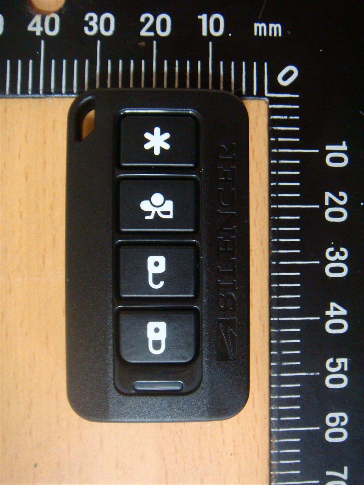
Compliance Certification Services Inc. Report No.: T100511202 Date of Issue: May 31, 2010 Page 1 Total Page: 4 Rev. 00 PHOTOGRAPHS OF EUT Compliance Certification Services Inc. Report No.: T100511202 Date of Issue: May 31, 2010 Page 2 Rev. 00 Compliance Certification Services Inc. Report No.: T100511202 Date of Issue: May 31, 2010 Page 3 Rev. 00
ID Label/Location Info
FCC ID LABEL FORMAT AND LOCATION Advance Security Inc. FCC ID: H5OR54 FCC ID: H5OR54 Model No.: CA6150RX This device complies with part 15 of the FCC Rules. Operation is subject to the following two conditions: (1) This device may not cause harmful interference, and (2) this device must accept any interference received, including interference that may cause undesired operation. FCC ID LABEL AREA
Internal Photos
Compliance Certification Services Inc. Report No.: T100511202 Date of Issue: May 31, 2010 Page 2 Rev. 00
Test Report
Compliance Certification Services Inc. Report No.: T100511202-F FCC ID: H5OR54 Date of Issue: May 31, 2010 Page 1 Total Page: 17 Rev. 00 FCC 47 CFR PART 15 SUBPART B TEST REPORT For Car Alarm Receiver Model: CA6150RX Brand Name: Advance Security Inc. Issued to Advance Security Inc. 3F, 48 Ta An Street, Hsi Chih, Taipei Hsien, TAIWAN R.O.C. Issued by Compliance Certification Services Inc. Sindian BU. No.163-1, Jhongsheng Rd., Sindian City, Taipei County 23151, Taiwan TEL: (02) 2217-0894 FAX: (02) 2217-1029 Note: This report shall not be reproduced except in full, without the written approval of Compliance Certification Services Inc. Ltd. This document may be altered or revised by Compliance Certification Services Inc. personnel only, and shall be noted in the revision section of the document. Compliance Certification Services Inc. Report No.: T100511202-F FCC ID: H5OR54 Date of Issue: May 31, 2010 Page 2 Rev. 00 TABLE OF CONTENTS 1 TEST RESULT CERTIFICATION .......................................................................................... 3 2 EUT DESCRIPTION .................................................................................................................. 4 3 TEST METHODOLOGY........................................................................................................... 4 3.1 EUT SYSTEM OPERATION............................................................................................. 4 3.2 DECISION OF FINAL TEST MODE ............................................................................... 5 4 SETUP OF EQUIPMENT UNDER TEST................................................................................ 5 5 FACILITIES AND ACCREDITATIONS................................................................................. 6 5.1 FACILITIES ........................................................................................................................ 6 5.2 LABORATORY ACCREDITATIONS AND LISTINGS ................................................. 6 6 INSTRUMENT AND CALIBRATION..................................................................................... 7 6.1 MEASUREMENT UNCERTAINTY ................................................................................. 7 6.2 MEASURING INSTRUMENT CALIBRATION ............................................................. 7 6.3 TEST AND MEASUREMENT EQUIPMENT ................................................................. 7 7 LINE CONDUCTED & RADIATED EMISSION TEST........................................................ 9 7.1 LIMIT ................................................................................................................................. 9 7.2 TEST PROCEDURE OF LINE CONDUCTED EMISSION........................................ 10 7.3 TEST PROCEDURE OF RADIATED EMISSION ....................................................... 12 7.4 TEST RESULTS ................................................................................................................ 14 APPENDIX I - PHOTOGRAPHS OF TEST SETUP.................................................................. 17 Compliance Certification Services Inc. Report No.: T100511202-F FCC ID: H5OR54 Date of Issue: May 31, 2010 Page 3 Rev. 00 1 TEST RESULT CERTIFICATION Applicant: Advance Security Inc. 3F, 48 Ta An Street, Hsi Chih, Taipei Hsien, TAIWAN R.O.C. Manufacturer: Advance Security Inc. 3F, 48 Ta An Street, Hsi Chih, Taipei Hsien, TAIWAN R.O.C. Equipment Under Test: Car Alarm Receiver Brand Name: Advance Security Inc. Model: CA6150RX Detailed EUT Description: See Item 2 of this report Date of Test: May 25, 2010 Applicable Standard Class / Limit Te s t R e s u l t FCC Part 15 Subpart B IC ICES-003 Class B No non-compliance noted Deviation from Applicable Standard None The above equipment was tested by Compliance Certification Services Inc. for compliance with the requirements set forth in the FCC Rules and Regulations Part 15, Subpart B and the measurement procedures were according to ANSI C63.4. This said equipment in the configuration described in this report shows the maximum emission levels emanating from equipment are within the compliance requirements. Compliance Certification Services Inc. Report No.: T100511202-F FCC ID: H5OR54 Date of Issue: May 31, 2010 Page 4 Rev. 00 2 EUT DESCRIPTION Product Car Alarm Receiver Brand Name Advance Security Inc. Model CA6150RX Housing Type Plastic EUT Power Rating 12VDC Receiver Frequency 433.92MHz Number of Channels 1 Channel Operating Mode Point-to-Point Note: The product is a composite system includes Transmitter and Receiver. This submittal(s) (test report) is intended for FCC ID: H5OR54 filing to comply with FCC Part 15 Subpart B Rules. The composite system (Transmitter) is intended for FCC ID: H5OT49 is compliance with FCC Part 15 Subpart C Rules. I/O PORT OF EUT I/O Port Type Q’TY TESTED WITH Note: Client consigns only one model sample (Model Number is CA6150RX) to test. 3 TEST METHODOLOGY 3.1 EUT SYSTEM OPERATION 1. Turn on the EUT to test. Note: Test program is self-repeating throughout the test. Compliance Certification Services Inc. Report No.: T100511202-F FCC ID: H5OR54 Date of Issue: May 31, 2010 Page 5 Rev. 00 3.2 DECISION OF FINAL TEST MODE 1. The following test mode(s) were scanned during the preliminary test: Mode: 1. Normal Mode 2. After the preliminary scan, the following test mode was found to produce the highest emission level. Radiation: Mode 1 Then, the EUT configuration and cable configuration of the above highest emission mode was recorded for all final test items. 4 SETUP OF EQUIPMENT UNDER TEST Setup Diagram See test photographs attached in Appendix I for the actual connections between EUT and support equipment. Support Equipment No Device Type Model Serial No. FCC ID/ BSMI ID Tra de Na me Data Cable Power Cord 1 Tool CA6550RX N/A N/A Advance Security Inc. To EU T: Unshielded, 2.5m 3 pin Cable: Unshielded, 0.85m N/A 2 Adaptor 91-56809 N/A N/A N/A N/A Unshielded, 1…
Text truncated - open the document above for the full version.
Test Setup Photos
Compliance Certification Services Inc. Report No.: T100511202-F FCC ID: H5OR54 Date of Issue: May 31, 2010 Page 17 Rev. 00 APPENDIX I - PHOTOGRAPHS OF TEST SETUP RADIATED EMISSION TEST
Contact Information
Applicant
Michael Chen(SAL)
Test Firm
Compliance Certification Services Inc.Rick Yeo
Technical Specifications
| # | Rule Parts | Frequency Range | Power Output |
|---|---|---|---|
| 1 | 15B | 433.92 MHz - 433.92 MHz | - |
Other Applications from Advance Security Inc
H5OT62
Dec 11, 2015Remote Control
Equipment Class
DSC - Part 15 Security/Remote Control Transmitter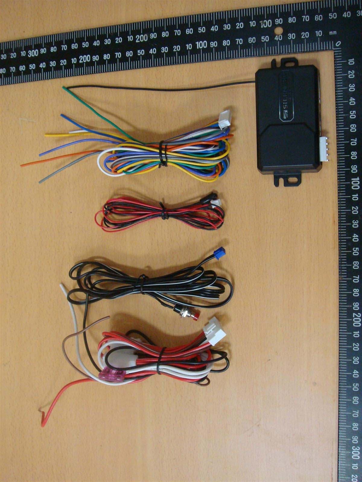
H5OR57
Dec 11, 2015Remote Control
Equipment Class
CYY - Communications Receiver used w/Pt 15 Transmitter
H5OTR64
Oct 22, 2015Remote Control
Equipment Class
DSS - Part 15 Spread Spectrum Transmitter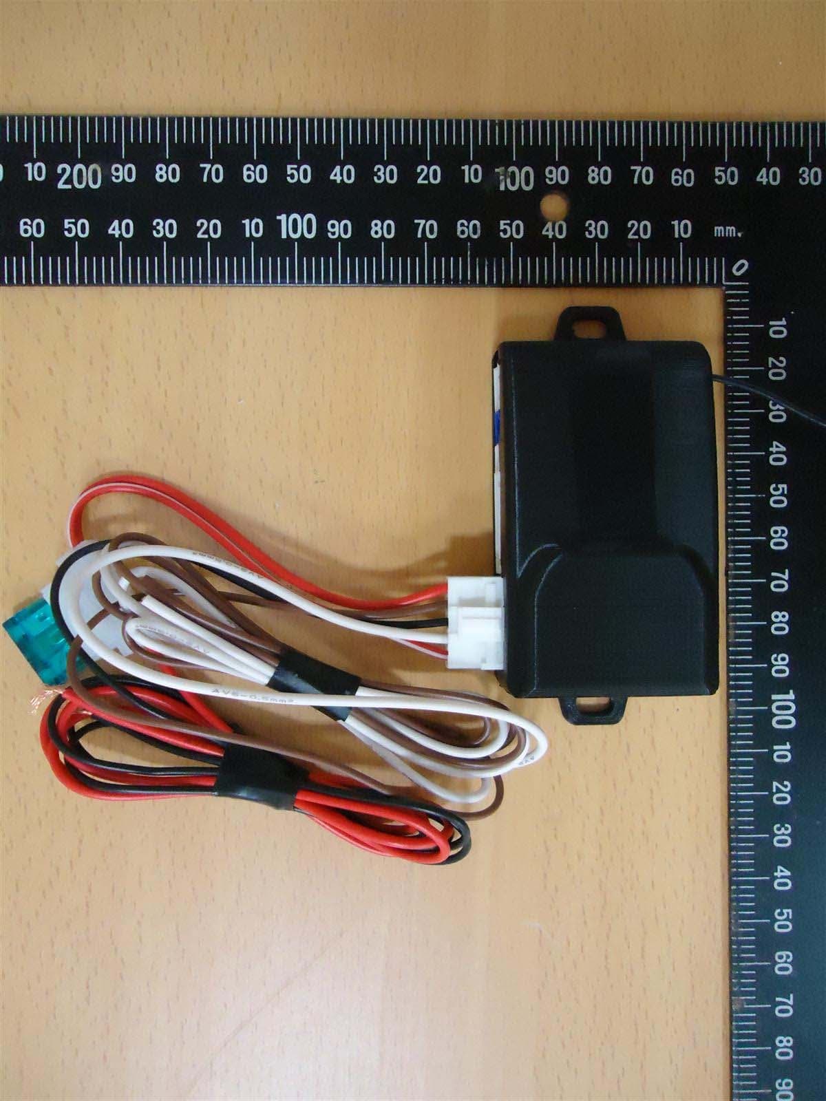
H5OR56
Sep 10, 2015Remote Control
Equipment Class
CYY - Communications Receiver used w/Pt 15 Transmitter
H5OT61
Sep 07, 2015Remote Control
Equipment Class
DSC - Part 15 Security/Remote Control Transmitter