H5OT23Car Alarm Transmitter
Advance Security Inc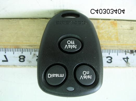
Click to zoom
Application Details
- Equipment Class
- DSC - Part 15 Security/Remote Control Transmitter
- Date of Grant
- Mar 09, 2004
- Application Purpose
- Original Equipment
- Date of Application
- Mar 09, 2004
- Equipment Note
- Car Alarm Transmitter
- Frequency Range
- 302.00000000 - 302.00000000
- Company
- Advance Security Inc
- Country
- Taiwan
Documents & Files
Document Text
Text extracted from the exhibit documents filed with the FCC. Open a document above to read the original.
Users Manual
OWNER’S MANUAL Model: SLRF8 Vehicle Immobilizer This device complies with part 15 of the FCC rules. Operation is subject to the following two conditions: (1) This device may not cause harmful interference; and (2) This device must accept any interference received, including interference that may cause undesired operation. Note: The manufacturer is not responsible for any radio or TV interference caused by unauthorized modifications to this equipment. Such modifications could void the user’s authority to operate the equipment. 4900UM 3/2/04 12:59 PM Page 1 Welcome to the world of Silencer ® automotive security. Silencer automotive security products have been designed to provide the consumer with a product that is technologically superior, providing years of trouble free operation. This manual will provide reference for the operation and maintenance of your new Silencer vehicle immobilizer system. This system is an automatic device that will become armed every time you leave your vehicle. Once armed, the Silencer vehicle immobilizer will prevent your vehicle's engine from operating, aiding in the prevention of vehicle theft. Take a moment to read this manual so you will be familiar with the operation of your new system. Passive Arming Once you have turned the ignition key to the "Off" position, the Silencer engine immobilizer will become armed in 30 seconds. Upon arming, the device will emit 1 chirp sound to indicate it’s "Armed". If you turn the ignition key back on before the 30 seconds has elapsed, the system will reset and wait for the ignition key to be turned to the "Off" position again. Note: This passive arming feature could qualify in some states for an insurance discount. Check with your insurance agency. When you return to your vehicle to start the engine, press the “Disarm” button on the 3-button transmitter. When the system is disarmed, the device will emit 2 chirps to indicate it’s "Disarmed". Manual Disarm – 3-Button Transmitter Manual Disarm – 1-Button Transmitter When you return to your vehicle to start the engine, press the button on the transmitter. When the system is disarmed, the device will emit 2 chirps to indicate it’s "Disarmed". Disarm Valet On Valet Off 3-Button Transmitter1-Button Transmitter 2 4900UM 3/2/04 12:59 PM Page 2 Each time the system is disarmed using the transmitter, the device will begin a protection mode countdown. This is a timed secondary protection mode to insure the RF signal that disarmed the system came from your transmitter. If you do not start your vehicle within the 60 second timer countdown, your Silencer system will become rearmed and your engine will be disabled. RF Protection Mode Emergency Override There may come a time when it will be necessary to manually disarm your Silencer system without using your transmitter. This condition occurs if the battery in your transmitter is low, dead or if your transmitter becomes damaged or lost. In these circumstances, it will be necessary to use your ignition key to perform an emergency override procedure to get your vehicle operational. Follow this procedure to manually override your system: 1. Turn on the ignition key for 10 seconds then turn it off. 2. Wait for 10 seconds. 3. Turn on the ignition key for 10 seconds then turn it off. 4. Wait for 10 seconds 5. Turn on the ignition key and the vehicle will start. The only maintenance that your Silencer engine immobilizer requires is a periodic check to insure that all operations are functioning normally. This is also good practice for you to refresh your memory on “Emergency Override” and “Valet Mode” procedures. System Maintenance The batteries supplied with yourremote controls should last over 1 year. Heavy transmitter usage will shorten battery life. Reduced transmitter range is usually a indication that the batteries are becoming weak and should be replaced. Transmitters that are not in use should have the batteries removed. Batteries (Only applies if you have a 3-button transmitter) The valet mode allows you to temporarily turn off the passive arming function, eliminating the need to give your transmitter to a parking attendant or garage mechanic. To enter the valet mode, follow this procedure: 1. Press the disarm button on your transmitter to insure the device is disarmed (you will hear 2 beeps from the device). 2. Within 3 seconds of pressing the disarm button, press and release the “Valet On” button 3 times slowly. The device will emit 3 long beeps to indicate the valet mode "On" condition. To exit the valet mode, follow this procedure: 1. Press the "Disarm" button on your transmitter (you will not hear any sound). 2. Within 3 seconds of pressing the disarm button, press and release the “Valet Off” button 3 times slowly. The device will emit 1 long beep to indicate the valet mode is "Off". Valet Mode 3 4900UM 3/2/04 12:59 PM Page 3 3 Year Warranty Your new Silencer ® Security Systemsis warranted to be free of defects for 3 years. Silencer ® or its authorized agents will within 3 years from the date of sale to you, repair or replace said product or any part thereof, at the option of the Silencer ® or its authorized agents, if said product or part is found defective in materials or workmanship, when properly connected and operating on the correct power requirements designated for the specific product. This warranty and Silencer ® or its authorized agents obligations hereunder do not apply where the product was; damaged while in the possession of the consumer, subjected to unreasonable or unintended use, not reasonably maintained, or serviced by anyone other than Silencer ® or its authorized agents, or where the warning seal on the product is broken or the power and/ or plugs are detached from the unit. This war ranty does not cover the cabinet appearance items or accessories used in connection with this product, or any damage to the products resulting from improper installation, alteration, accident, misuse, abuse or acts of nature. Silencer…
Text truncated - open the document above for the full version.
External Photos
Report Number: C40303404-RP March 8, 2004 Page 12 Rev. 00 External of EUT
ID Label/Location Info
FCC ID LABEL FORMAT AND LOCATION Applicant: Advance Security Inc. FCC ID: H5OT23 FCC ID: H5OT23 This device complies with part 15 of the FCC Rules. Operation is subject to the following two conditions: (1) This device may not cause harmful interference, and (2) this device must accept any interference received, including interference that may cause undesired operation. FCC ID LABEL AREA
Internal Photos
Report Number: C40303404-RP March 8, 2004 Page 13 Rev. 00 Internal of EUT Report Number: C40303404-RP March 8, 2004 Page 14 Rev. 00
Operational Description
SLRF8 Operational Description The car alarm transmitter is a low powered, hand held unit for remote controlling the car locks and other features. See the function descriptions in attached. The transmitter is powered by a 3 volt battery. It is designed to operated on a single fixed frequency at 302 MHz. See the attached block diagram and schematic. There are 3 buttons trigger the integrated circuit (U1) which produces the digital control signals and will modulate the carrier signal. The carrier signal is generated by a crystal oscillator/ amplifier circuit comprised of a 302 MHz crystal (X1) and a npn transmitter (Q1). The modulated output of the RF amplifier stage is coupled to the PCB strip antenna. The coupling network comprised of L1, C2 and C3. The strip antenna is attached on PCB permanently around 20 mm. The transmitter is manually operated by the buttons pushed and will automatically deactivate within 3 seconds after the button being released. This feature is incorporated by the U1 internally. All tuning and verification are performed by the manufacture and there are no adjustments can be made by the user. No external ground is required or used with this transmitter.
Test Report
Report Number: C40303404-RP March 8, 2004 Page 1 of 15 Rev. 00 FCC ELECTROMAGNETIC EMISSIONS COMPLIANCE REPORT CERTIFICATION TO FCC PART 15 REQUIREMENTS for INTENTIONAL RADIATOR of Car Alarm Transmitter FCC ID Number : H5OT23 Trade Name : Advance Security Inc. Model Number : SLRF8 Agency Series : N/A Report Number : C40303404-RP Date : March 8, 2004 Prepared for Advance Security Inc. 3F, 48 Ta An Street, Hsi Chih, Taipei Hsien, Taiwan, R.O.C. Prepared by Compliance Certification Services Inc. Hsintien Lab. No. 165, Chunghsen Road, Hsintien City Taipei Hsien, Taiwan TEL: (02) 2217-0894 FAX: (02) 2217-1029 This report shall not be reproduced, except in full, without the written approval of Compliance Certification Services Inc. Report Number: C40303404-RP March 8, 2004 Page 2 Rev. 00 TABLE OF CONTENTS 1. VERIFICATION OF COMPLIANCE......................................................3 2. PRODUCT DESCRIPTION.....................................................................4 3. TEST FACILITY.......................................................................................4 4. MEASUREMENT STANDARDS.............................................................4 5. TEST METHODLOGY............................................................................4 6. MEASUREMENT EQUIPMENT USED.................................................5 7. POWERLINE RFI LIMIT.......................................................................5 8. RADIATED EMISSION LIMITS.............................................................6 9. SYSTEM TEST CONFIGURATION.......................................................6 10. TEST PROCEDURE................................................................................7 11. EQUIPMENT MODIFICATIONS...........................................................8 12. TEST RESULT..........................................................................................9 12.1. MAXIMUM MODULATION PERCENTAGE(M%)...........................9 12.2. THE EMISSIONS BANDWIDTH.......................................................10 APPENDIX 1 PHOTOGRAPHS OF EUT....................................................11 APPENDIX 2 TEST DATA...........................................................................15 Report Number: C40303404-RP March 8, 2004 Page 3 Rev. 00 1. VERIFICATION OF COMPLIANCE COMPANY NAME : Advance Security Inc. 3F, 48 Ta An Street, Hsi Chih, Taipei Hsien, Taiwan, R.O.C. CONTACT PERSON : Michael Chen / President TELEPHONE NO. : (886-2) 8648-1688 EUT DESCRIPTION : Car Alarm Transmitter MODEL NAME/NUMBER : SLRF8 FCC ID : H5OT23 DATE TESTED : March 3, 2004 & March 4, 2004 REPORT NUMBER : C40303404-RP TYPE OF EQUIPMENT SECURITY EQUIPMENT (INTENTIONAL RADIATOR) EQUIPMENT TYPE 302 MHz Car Alarm Transmitter MEASUREMENT PROCEDURE ANSI 63.4 / 2001 LIMIT TYPE CERTIFICATION FCC RULE CFR 47, PART 15 The above equipment was tested by Compliance Certification Services Inc. for compliance with the requirements set forth in the FCC CFR 47, PART 15. The results of testing in this report apply to the product/system which was tested only. Other similar equipment will not necessarily produce the same results due to production tolerance and measurement uncertainties. Warning: This document reports conditions under which testing was conducted and results of tests performed. This document may not be altered or revised in any way unless done so by Compliance Engineering Services, Inc. and all revisions are duly noted in the revisions section. Any alteration of this document not carried out by Compliance Certification Services Inc. will constitute fraud and shall nullify the document. Vince Chiang / Supervisor Compliance Certification Services Inc. Report Number: C40303404-RP March 8, 2004 Page 4 Rev. 00 2. PRODUCT DESCRIPTION Fundamental Frequency 302 MHz Power Source 3V Battery Transmitting Time Periodic < 5 seconds Associated Receiver Model: H5OR38 (FCC ID) 3. TEST FACILITY The open area test sites and conducted measurement facilities used to collect the radiated data are located at No. 165 & No. 199, Chung Sheng Road, Hsin Tien City, Taipei, Taiwan R.O.C. The sites are constructed in conformance with the requirements of ANSI C63.7, ANSI C63.4 and CISPR Publication 22. 4. MEASUREMENT STANDARDS The site is constructed and calibrated in conformance with the requirements of ANSI C63.4/2001. 5. TEST METHODOLOGY For an intentional radiator, the spectrum shall be investigated from the lowest radio frequency signal generated in the device, without going below 9 KHz, up to at least the tenth harmonic of the highest fundamental frequency or to 40 GHz, whichever is lower. (CFR 47 Section 15.33) Report Number: C40303404-RP March 8, 2004 Page 5 Rev. 00 6. MEASUREMENT EQUIPMENT USED Manufacturer Model Number Description Cal Due Date ADVANTEST R3261A SPECTRUM ANALYZER 04/11/04 R&S ESVS30 MEASURE RECEIVER 09/30/04 SCHWARZBECK VULB 9160 ANTENNA 05/09/04 BELDEN 9913 CABLE 01/01/05 H.P. 8447D B PRE-AMPLIFIER 05/03/04 CCS N/A Site NSA 10/30/04 EMCO 3115 ANTENNA(1-18GHz) 02/02/05 HP 8449B AMPLIFIER(1-26.5GHz) 02/15/05 JYEBAO LL143 CABLE(1-18GHz) 02/15/05 JYEBAO LL142 CABLE(1-18GHz) 02/15/05 HP 8566B EMC ANALYZER(100Hz-22GHz) 06/25/04 7. POWERLINE RFI LIMIT CONNECTED TO AC POWER LINE SECTION 15.207 CARRIER CURRENT SYSTEM IN THE FREQUENCY RANGE OF 450 KHz TO 30 MHz SECTION 15.205 AND SECTION 15.209, 15.221, 15.223, 15.225 OR 15.227, AS APPROPRIATE. BATTERY POWER NO REQUIRED. Report Number: C40303404-RP March 8, 2004 Page 6 Rev. 00 8. RADIATED EMISSION LIMITS GENERAL REQUIREMENTS SECTION 15.209 RESTRICTED BANDS OF OPERATION SECTION 15.205 PERIODIC OPERATION IN THE BAND 40.66 -40.70 MHz AND ABOVE 70 MHz. SECTION 15.231 9. SYSTEM TEST CONFIGURATION Use a block of foam and combined it with EUT wrapping rubber band around it. This way it can test X.Y, and Z axis. To activate continuous transmission, place a small plastic block between rubber band and EUT push button. Radiated Open Site Test Set-up Report Nu…
Text truncated - open the document above for the full version.
Test Setup Photos
Report Number: C40303404-RP March 8, 2004 Page 6 Rev. 00 8. RADIATED EMISSION LIMITS GENERAL REQUIREMENTS SECTION 15.209 RESTRICTED BANDS OF OPERATION SECTION 15.205 PERIODIC OPERATION IN THE BAND 40.66 -40.70 MHz AND ABOVE 70 MHz. SECTION 15.231 9. SYSTEM TEST CONFIGURATION Use a block of foam and combined it with EUT wrapping rubber band around it. This way it can test X.Y, and Z axis. To activate continuous transmission, place a small plastic block between rubber band and EUT push button. Radiated Open Site Test Set-up
Contact Information
Applicant
Michael Chen(SAL)
Test Firm
Compliance Certification Services Inc.Kurt Chen
Technical Specifications
| # | Rule Parts | Frequency Range | Power Output |
|---|---|---|---|
| 1 | 15.231 | 302 MHz - 302 MHz | - |
Other Applications from Advance Security Inc
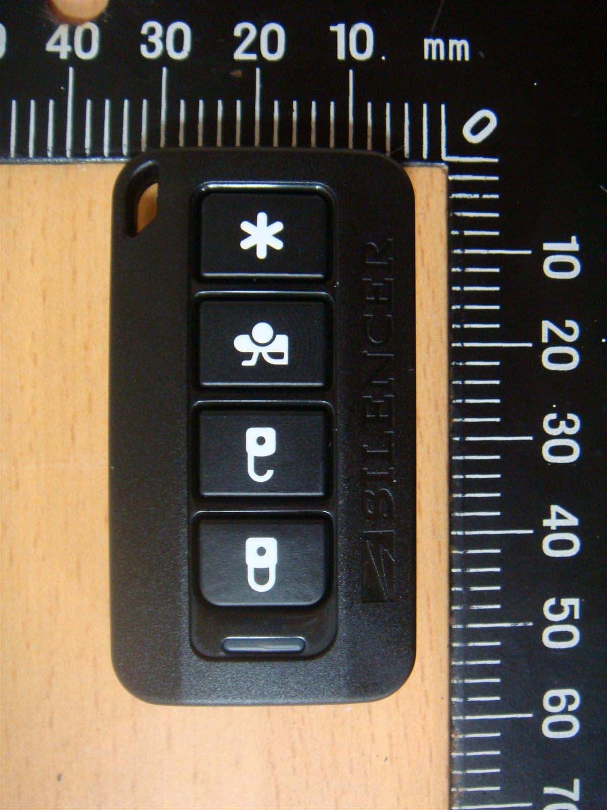
H5OT62
Dec 11, 2015Remote Control
Equipment Class
DSC - Part 15 Security/Remote Control Transmitter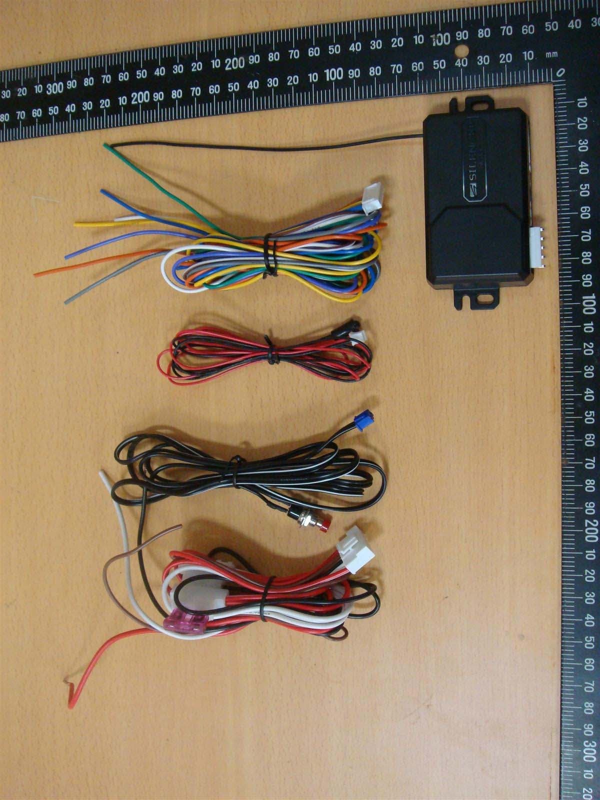
H5OR57
Dec 11, 2015Remote Control
Equipment Class
CYY - Communications Receiver used w/Pt 15 Transmitter
H5OTR64
Oct 22, 2015Remote Control
Equipment Class
DSS - Part 15 Spread Spectrum Transmitter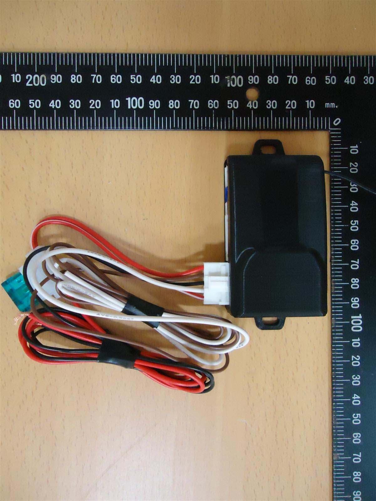
H5OR56
Sep 10, 2015Remote Control
Equipment Class
CYY - Communications Receiver used w/Pt 15 Transmitter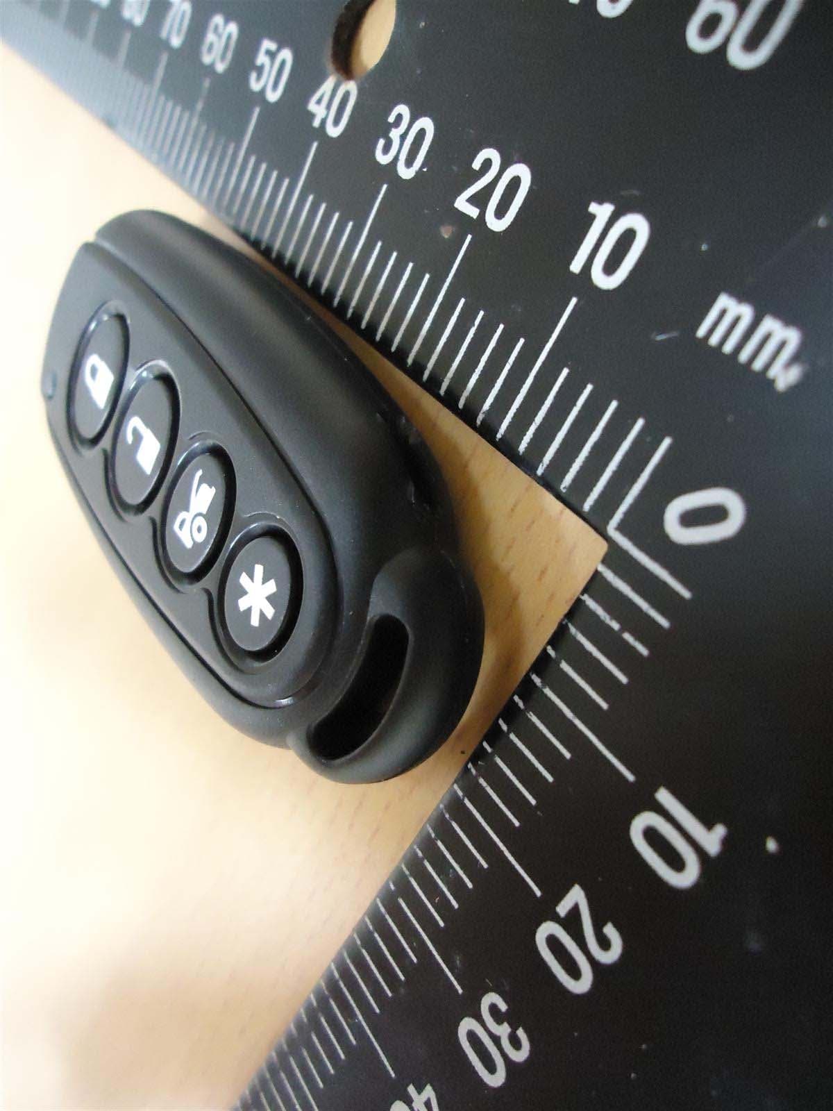
H5OT61
Sep 07, 2015Remote Control
Equipment Class
DSC - Part 15 Security/Remote Control Transmitter