H5OT29Car Alarm Transmitter
Advance Security Inc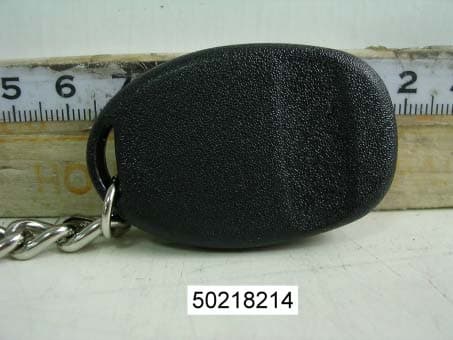
Click to zoom
Application Details
- Equipment Class
- DSC - Part 15 Security/Remote Control Transmitter
- Date of Grant
- Mar 06, 2005
- Application Purpose
- Original Equipment
- Date of Application
- Mar 06, 2005
- Equipment Note
- Car Alarm Transmitter
- Frequency Range
- 433.92000000 - 433.92000000
- Company
- Advance Security Inc
- Country
- Taiwan
Documents & Files
Document Text
Text extracted from the exhibit documents filed with the FCC. Open a document above to read the original.
Users Manual
OWNER’S MANUAL Model: PLUS-4800 For Technical Assistance, please call (800) 638-3600, or visit www.magnadyne.com R Vehicle Security PLUS-4800-UM.qxp 2/7/05 2:43 PM Page 1 2 Congratulations on your purchase of a quality Carbine automotive security system. Carbine automotive security products have been designed to provide the consumer with a product that is technologically superior and will provide years of trouble free operation. The information enclosed will provide a ready reference of the operation and maintenance of your new security system. Remote Control Transmitters 1. Exit the vehicle and close all entrances. 2. Press and release the LOCK button. The security system will respond as follows: A. The horn/siren will chirp one time. B. The LED indicator will begin to flash at a steady rate. C. The parking lights will flash one time. D. The starter disable device will become armed and the vehicle engine will not crank. E. All protected entrances are armed. Note:If the dome light is on or a sensor is active at the time you arm your security system, you will hear the horn/siren beep one time and then you will hear another beep from the horn/siren about 5 seconds later. The second beep is the active sensor warning indicator. This second beep tells you that the alarm is armed but one of the sensors has been temporarily deleted because it was “On” at the time the alarm was armed. The security system is now fully armed! Security System Operation:(using the transmitter to arm the security system) AB Note: The following information is valid only if your security system has been programmed to automatically arm. 1. Turn off the ignition key and exit the vehicle. 2. Close all protected entrances. After the last protected entrance is closed the horn/siren will chirp one time and the LED indicator will begin to flash fast. The fast flashing LED indicates that the automatic arming timer is counting down and the security system will become armed within 30 seconds. After 30 seconds has passed, the security system will respond in the following manner: Automatic Arming(without using the transmitter) Lock Unlock Panic Aux Regular Transmitter Lock Unlock Panic Aux Passive Transmitter (Optional) Passive Unlocking PLUS-4800-UM.qxp 2/7/05 2:43 PM Page 2 A. The horn/siren will chirp one time. B. The LED indicator will begin to flash slower. C. The parking lights will flash one time. D. All protected entrances are armed. Note 1:Re-opening a protected entrance before the system becomes armed will stop the arming timer. After closing the entrance the timer will begin counting again from zero. Note 2:If the vehicle has a delayed interior lighting system, the automatic arming timer will start counting after the interior lighting has turned itself Off. This could add up to 45 seconds to the total automatic arming countdown time (up to 75 seconds total arming delay). The security system is now fully armed! 3 Automatic Arming(without using the transmitter)(Continued) Press and release the UNLOCK button. The security system will respond as follows: A. The horn/siren will chirp two times. B1.The LED indicator will be Off (only if Auto Arming is programmed Off). B2.The LED indicator will be flashing very fast (only if Auto Arming is programmed On). C. The parking lights will flash two times. Note: If you are disarming the security system after it has been triggered and the horn/siren is sounding, the disarm chirps are automatically deleted. Disarming the Security System Using the Regular Transmitter(A) Override Switch Operation Your Carbine security system is supplied with a override switch system. This switch is used to override the security system in the event that the transmitters are lost or fail to operate, and to put the security system in non-operational mode. Disarming the Security System Using the Passive Transmitter (B) Note: When using the passive transmitter the on/off switch must be in the “On” position. A. Walk toward your vehicle and the security system will respond the same as pushing the UNLOCK button. The security system is now disarmed! PLUS-4800-UM.qxp 2/7/05 2:43 PM Page 3 4 Override Switch Operation(Continued) Override Operation:(Security System is Armed) 1. Enter the vehicle (the security system will begin sounding at this point). 2. Place the ignition key into the ignition switch and turn the switch to the “On” position. 3. Within 5 seconds of turning the ignition key “On”, place the override switch to the “On” position. 4. The horn/siren will stop sounding. 5. The LED indicator will be solid red. The security system is overridden. Note 1:If the override switch is already in the “On” position when you turn “On” the ignition key, the override function will be bypassed. Turn “Off” the ignition key, place the override switch in the “Off” position and try again. Note 2:If you fail to place the overrideswitch to the “On” position within 5 seconds of turning “On” the ignition key, the override function will be locked-out. Place the switch in the “Off” position, turn “Off” the ignition key and try again. Remote Panic: Press and hold the LOCK or PANIC button for more than 3 seconds and the security system will respond in the following manner: A. The horn/siren will begin sounding. B. The parking lights will begin flashing. To turn off the panic alarm, press and release the UNLOCK or PANIC button. The horn/siren will stop sounding and the parking lights will stop flashing. Note:If you do not turn off the panic feature with the transmitter, the panic alarm will sound for 60 seconds and then turn off by itself. Remote Valet Mode Operation: Activate Valet Mode 1. Turn the ignition key to the “Off” position and open any door. 2. Press and hold down the LOCK + * buttons. 3. The door locks will lock and unlock. Release the buttons. 4. The LED will begin to flash every 5 seconds indicating that the system is in Valet Mode. Exit Valet Mode 1. Turn the ignition key to the “Off” position and open any door. 2. Press…
Text truncated - open the document above for the full version.
Block Diagram
1 2 34 ABCD 4 3 2 1 D CBA
External Photos
Compliance Certification Services Inc. Report No.: 50218214 Date of Issue: February 24, 2005 Page PHOTOGRAPHS OF EUT
ID Label/Location Info
FCC ID LABEL FORMAT AND LOCATION Advance Security Inc. FCC ID: H5OT29 FCC ID: H5OT29 This device complies with part 15 of the FCC Rules. Operation is subject to the following two conditions: (1) This device may not cause harmful interference, and (2) this device must accept any interference received, including interference that may cause undesired operation. FCC ID LABEL AREA
Internal Photos
Compliance Certification Services Inc. Report No.: 50218214 Date of Issue: February 24, 2005 Page Compliance Certification Services Inc. Report No.: 50218214 Date of Issue: February 24, 2005 Page
Operational Description
CA-RC6HF Operational Description The car alarm transmitter is a low powered, hand held unit for remote controlling the car locks and other features. See the function descriptions in attached. The transmitter is powered by a 3 volt battery. It is designed to operate on a single fixed frequency at 433.92 MHz. See the attached block diagram and schematic. There are 1 buttons trigger the integrated circuit (U2) which produces the digital control signals and will modulate the carrier signal. The carrier signal is generated by a crystal oscillator/ amplifier circuit comprised of a 433.92 MHz crystal (X1) and a npn transmitter (Q1). The modulated output of the RF amplifier stage is coupled to the PCB strip antenna. The coupling network comprised of L1, C3 and C4. The strip antenna is attached on PCB permanently around 20 mm. The transmitter is manually operated by the buttons pushed and will automatically deactivate within 3 seconds after the button being released. This feature is incorporated by the U2 internally. All tuning and verification are performed by the manufacture and there are no adjustments can be made by the user. No external ground is required or used with this transmitter.
Schematics
1 2 34 ABCD 4 3 2 1 D CBA Title Number Revision Size A4 Date: 17-Feb-2005 Sheet of File: D:\DDB \T X\ CA-RC6HF.Dd b Drawn By: VDD 1 GP5 2 GP4 3 GP3 4 GP2 5 GP1 6 GP0 7 VSS 8 3V
Test Report
Compliance Certification Services Inc. Report No.: 50218214-RP1 FCC ID: H5OT29 Date of Issue: February 24, 2005 Page 1 of 25 Rev. 00 FCC ELECTROMAGNETIC EMISSIONS COMPLIANCE REPORT CERTIFICATION TO FCC PART 15 REQUIREMENTS for INTENTIONAL RADIATOR of Car Alarm Transmitter FCC ID Number : H5OT29 Trade Name : Advance Security Inc. Model Number : CA-RC6HF Agency Series : N/A Report Number : 50218214-RP1 Date : February 24, 2005 Issued to Advance Security Inc. 3F, 48 Ta An Street, Hsi Chih, Taipei Hsien, TAIWAN R.O.C. Issued by Compliance Certification Services Inc. Hsintien Lab. No. 165, Chunghsen Road, Hsintien City Taipei Hsien, Taiwan TEL: (02) 2217-0894 FAX: (02) 2217-1029 Note: This report shall not be reproduced except in full, without the written approval of Compliance Certification Services Inc. Ltd. This document may be altered or revised by Compliance Certification Services Inc. personnel only, and shall be noted in the revision section of the document. Compliance Certification Services Inc. Report No.: 50218214-RP1 FCC ID: H5OT29 Date of Issue: February 24, 2005 Page 2 Rev. 00 TABLE OF CONTENTS 1. VERIFICATION OF COMPLIANCE ............................................................... 3 2. PRODUCT DESCRIPTION................................................................................. 4 3. TEST FACILITY ................................................................................................... 4 4. MEASUREMENT STANDARDS ....................................................................... 4 5. TEST METHODLOGY ........................................................................................ 4 6. MEASUREMENT EQUIPMENT USED ........................................................... 5 7. POWERLINE RFI LIMIT.................................................................................... 5 8. RADIATED EMISSION LIMITS ....................................................................... 6 9. SYSTEM TEST CONFIGURATION ................................................................. 6 10. TEST PROCEDURE ............................................................................................. 7 11. EQUIPMENT MODIFICATIONS...................................................................... 8 12. TEST RESULT ....................................................................................................... 9 12.1. MAXIMUM MODULATION PERCENTAGE (M%)................................. 9 12.2. THE EMISSIONS BANDWIDTH ................................................................... 9 APPENDIX I TEST DATA ........................................................................................ 10 Compliance Certification Services Inc. Report No.: 50218214-RP1 FCC ID: H5OT29 Date of Issue: February 24, 2005 Page 3 Rev. 00 1. VERIFICATION OF COMPLIANCE COMPANY NAME : Advance Security Inc. 3F, 48 Ta An Street, Hsi Chih, Taipei Hsien, TAIWAN R.O.C. CONTACT PERSON : Michael Chen / President TELEPHONE NO. : 886-2-8648-1688 EUT DESCRIPTION : Car Alarm Transmitter MODEL NAME/NUMBER : CA-RC6HF FCC ID : H5OT29 DATE TESTED : February 22, 2005 REPORT NUMBER : 50218214-RP1 TYPE OF EQUIPMENT SECURITY EQUIPMENT (INTENTIONAL RADIATOR) EQUIPMENT TYPE 433.92 MHz Car Alarm Transmitter MEASUREMENT PROCEDURE ANSI 63.4 / 2003 LIMIT TYPE CERTIFICATION FCC RULE CFR 47, PART 15 The above equipment was tested by Compliance Certification Services Inc. for compliance with the requirements set forth in the FCC CFR 47, PART 15. The results of testing in this report apply to the product/system which was tested only. Other similar equipment will not necessarily produce the same results due to production tolerance and measurement uncertainties. Warning: This document reports conditions under which testing was conducted and results of tests performed. This document may not be altered or revised in any way unless done so by Compliance Certification Services Inc. and all revisions are duly noted in the revisions section. Any alteration of this document not carried out by Compliance Certification Services Inc. will constitute fraud and shall nullify the document. Approved by: Reviewed by: Compliance Certification Services Inc. Report No.: 50218214-RP1 FCC ID: H5OT29 Date of Issue: February 24, 2005 Page 4 Rev. 00 2. PRODUCT DESCRIPTION Fundamental Frequency 433.92 MHz Power Source 3V Battery Transmitting Time Periodic < 5 seconds Associated Receiver FCC ID: H5OR41 3. TEST FACILITY The open area test sites and conducted measurement facilities used to collect the radiated data are located at No. 165 & 199, Chunghsen Road, Hsintien City, Taipei Hsien, Taiwan The sites are constructed in conformance with the requirements of ANSI C63.7, ANSI C63.4 and CISPR Publication 22. 4. MEASUREMENT STANDARDS The site is constructed and calibrated in conformance with the requirements of ANSI C63.4/2003. 5. TEST METHODOLOGY For an intentional radiator, the spectrum shall be investigated from the lowest radio frequency signal generated in the device, without going below 9 KHz, up to at least the tenth harmonic of the highest fundamental frequency or to 40 GHz, whichever is lower. (CFR 47 Section 15.33) Compliance Certification Services Inc. Report No.: 50218214-RP1 FCC ID: H5OT29 Date of Issue: February 24, 2005 Page 5 Rev. 00 6. MEASUREMENT EQUIPMENT USED Open Area Test Site # I Name of Equipment Manufacturer Model Serial Number Calibration Due SITE NSA CCS I Site N/A 09/17/2005 MEASURE RECEIVER SCHAFFNER SCR3501 338 07/05/2005 SPECTRUM ANALYZER ADVANTEST R3132 120900008 No Calibration Required ANTENNA SCHAFFNER CBL 6112B 2809 09/24/2005 AMPLIFIER SCHAFFNER CPA9231A 3626 10/08/2005 CABLE BELDEN 9913 N-TYPE #I2 02/18/2006 ATTENUATOR MCL UNAT-6 AT06-3 10/08/2005 THERMO- HYGRO METER TFA N/A NO.2 11/09/2005 EMC ANALYZER (100Hz-22GHz) HP 8566B 2937A06102 07/26/2005 ANTENNA (1-18GHz) EMCO 3115 5761 01/17/2006 AMPLIFIER (1-18GHz) HP 8449B 3008A01266 02/16/2006 CABLE (1-18GHz) JYEBAO LL142 SMA#RS1&2 02/16/2006 Remark:…
Text truncated - open the document above for the full version.
Test Setup Photos
Compliance Certification Services Inc. Report No.: 50218214-RP1 FCC ID: H5OT29 Date of Issue: February 24, 2005 Page 6 Rev. 00 8. RADIATED EMISSION LIMITS GENERAL REQUIREMENTS SECTION 15.209 RESTRICTED BANDS OF OPERATION SECTION 15.205 PERIODIC OPERATION IN THE BAND 40.66 -40.70 MHz AND ABOVE 70 MHz. SECTION 15.231 9. SYSTEM TEST CONFIGURATION Use a block of foam and combined it with EUT wrapping rubber band around it. This way it can test X, Y and Z axis. To activate continuous transmitting & receiving, place a small plastic block between rubber band and EUT push button. Radiated Open Site Test Set-up
Contact Information
Applicant
Michael Chen(SAL)
Test Firm
Compliance Certification Services Inc.Kurt Chen
Technical Specifications
| # | Rule Parts | Frequency Range | Power Output |
|---|---|---|---|
| 1 | 15.231 | 433.92 MHz - 433.92 MHz | - |
Other Applications from Advance Security Inc
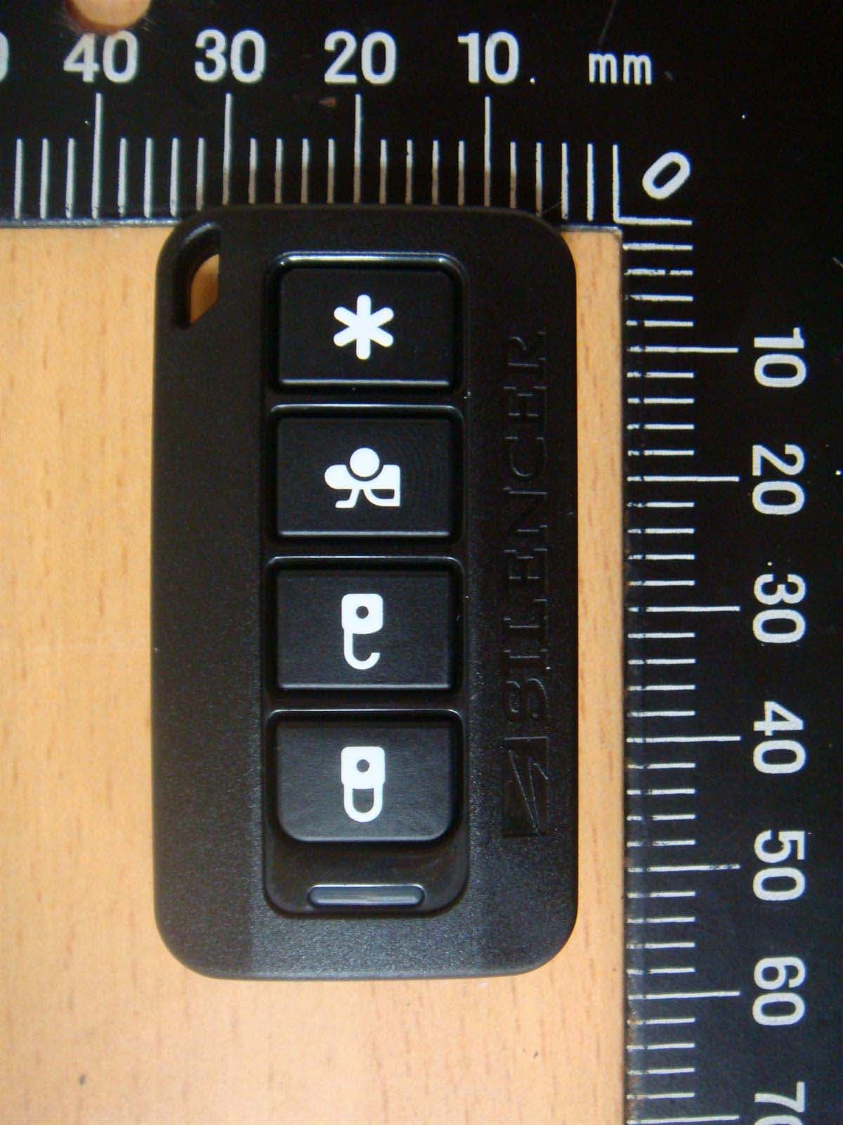
H5OT62
Dec 11, 2015Remote Control
Equipment Class
DSC - Part 15 Security/Remote Control Transmitter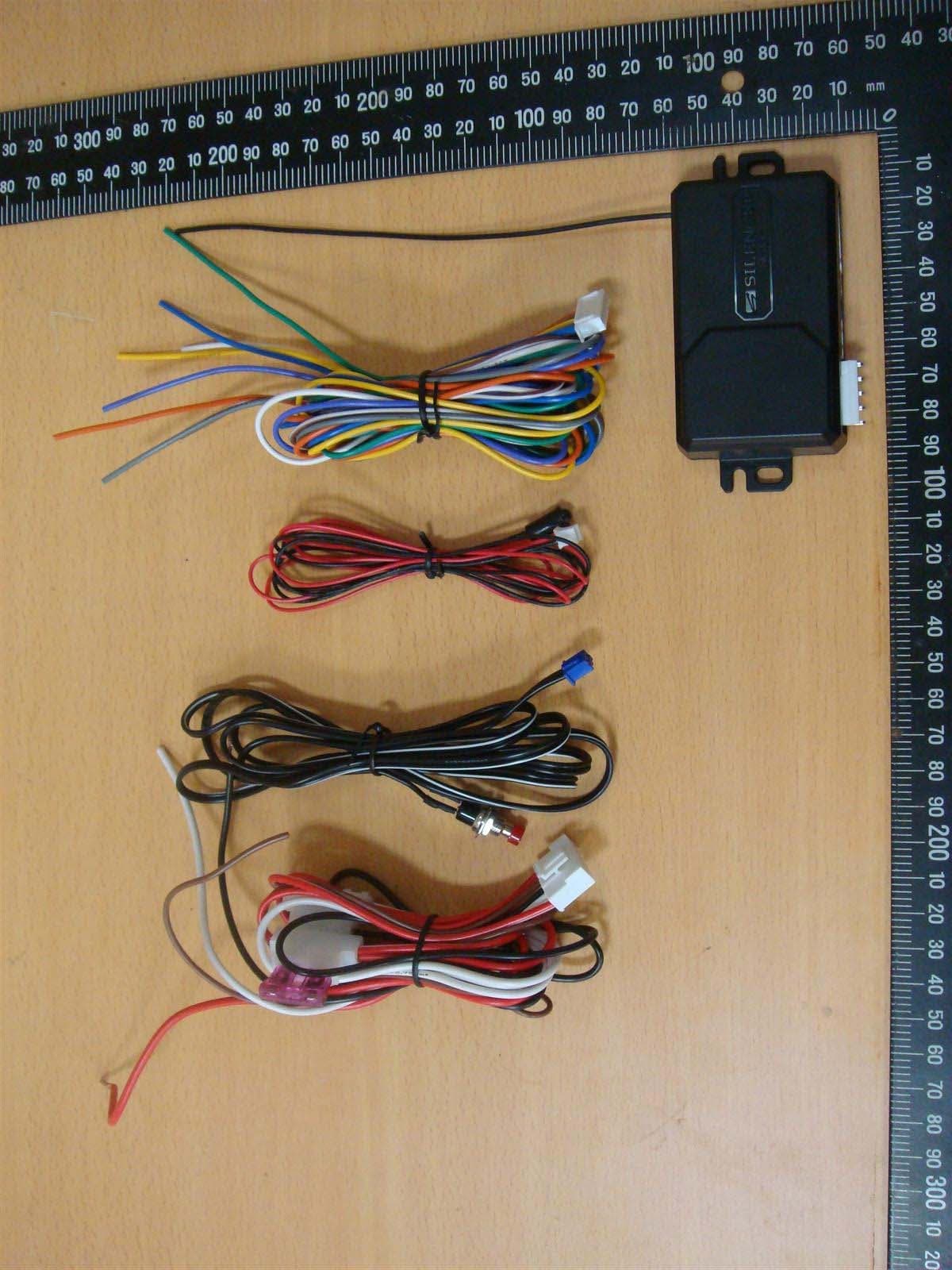
H5OR57
Dec 11, 2015Remote Control
Equipment Class
CYY - Communications Receiver used w/Pt 15 Transmitter
H5OTR64
Oct 22, 2015Remote Control
Equipment Class
DSS - Part 15 Spread Spectrum Transmitter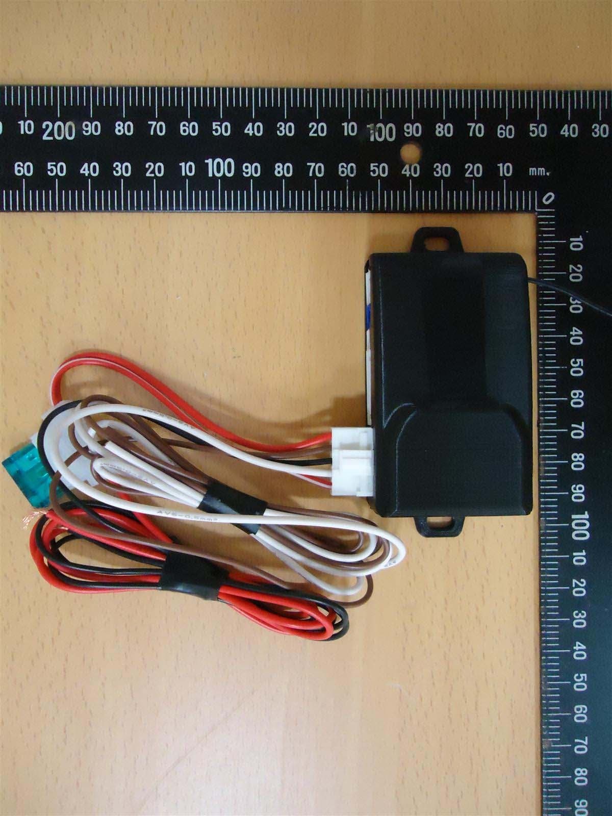
H5OR56
Sep 10, 2015Remote Control
Equipment Class
CYY - Communications Receiver used w/Pt 15 Transmitter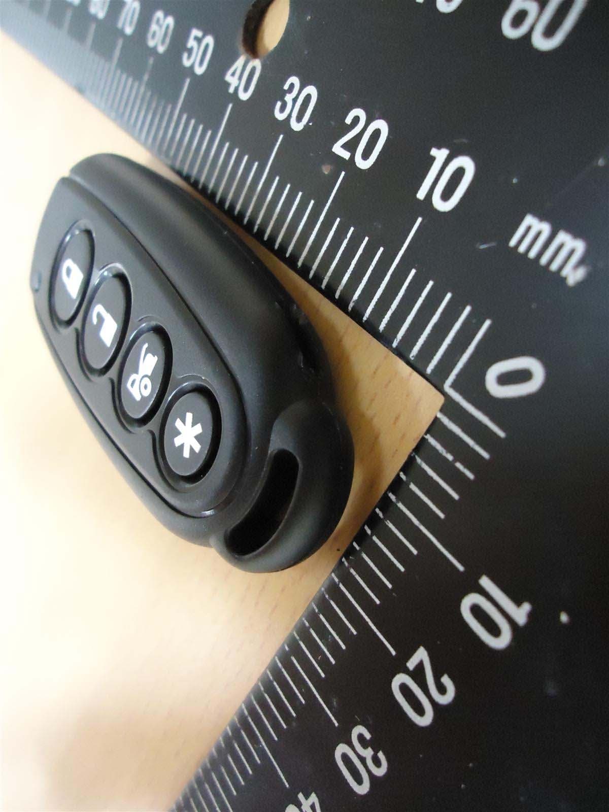
H5OT61
Sep 07, 2015Remote Control
Equipment Class
DSC - Part 15 Security/Remote Control Transmitter