H5OT35Remote Control
Advance Security Inc
Click to zoom
Application Details
- Equipment Class
- DSS - Part 15 Spread Spectrum Transmitter
- Date of Grant
- Jul 26, 2007
- Application Purpose
- Original Equipment
- Date of Application
- Jul 26, 2007
- Equipment Note
- Remote Control
- Frequency Range
- 909.00000000 - 921.77800000
- Company
- Advance Security Inc
- Country
- Taiwan
Documents & Files
Document Text
Text extracted from the exhibit documents filed with the FCC. Open a document above to read the original.
Users Manual
MODEL XRO-9100 REMOTE ENGINE STARTER WITH ALARM SYSTEM OWNER’S MANUAL 1 REMOTE TRANSCEIVER (TX) A. OLED DISPLAY Name of Transmitter Timer Door Lock Door Unlock In – Range Indicator Alarm Status Temperature Bypass Shock Sensor Battery Level Engine Running Melody Mode Count Down Timer Parking Timer Vibration Mode Alert Alarm Timer Start B. CHARGE THE BATTERY Power by built-in 3.7V lithium polymer battery, if the OLED screen display low battery or is flash, charge your remote transceiver. While the battery of the Remote Transceiver is under the battery charging, you can push the ” ” button to check charging condition. While the battery of the Remote Transceiver is under charging. Push the button; the screen will display Battery charging. C. MAIN PAGE: 1. Press the button, the screen will display main page. 2. While the icon flashing on the OLED screen, press the button, the OLED screen will display the detail of the flash icon, the display sequence of flash icon as follows: TRIGGERED / ENGINE RUNNING / COUNT DOWN TIMER / TIMER START / ALART TIMER condition. 2 While the TRIGGERED icon flash. Push the button to display triggered area. While the icon flash Push the button While the icon flash Push the button, the count down timer will display. Press the button 2to set off the count down time missing graphic or Or While the icon flash Push the button, the OLED screen will display individually i.e. daily start timer, timer start or temperature start, depend on which you selected. While the icon flash Push the button, the alert alarm time will display. Press the button 2 to set off the alert alarm timer D. SELECT THE TRANSCEIVER’S BUTTON CONFIGURATION: 1. Spin up the Switch to select the transceiver button configuration you need and the OLED screen will display the transceiver button configuration you select. 2. Within 5 seconds press the button 1, 2, 3 or 4 to remote control “button configuration” you selected. Note: If 5 seconds of inactivity expired, or push the button, the transceiver button configuration mode will exit. 3 Spin up the switch to the page 1 Spin up the switch to the page 2 Spin up the switch to the page 3 Spin up the switch to the page 4 Spin up the switch to the page 5 Spin up the switch resume to main page. E. SELECT THE TRANSCEIVER FEATURES: 1. Spin down the Switch to select the transceiver feature you need and the OLED screen will display the features you select. 2. Press the button 1, 2, 3 or 4 once within 3 seconds after finished selection and the OLED screen will change the display alternatively. Note: If 5 seconds of inactivity expire, or push the button, the transceiver features program mode will exit. Spin down the switch to the page 1 Spin down the switch to the page 2 Spin down the switch to the page 3 Spin down the switch to the page 4 Spin down the switch to the page 5 Spin down the switch to the page 6 Spin down the switch resume to main page. E- P1- 1. “BUTTON BI” SETTING: Example: Set the “Button Bi Disable”. It has a short “bi” sound while pressing the b utton of the remote transceiver Spin down the switch to the page 1 Press the button 1 and it will display previously setting Press the button 2 to change the setting Press the button and the setting is done. 4 E- P1- 2. “BUTTON LOCK” SETTING: Example: Set the “Button Lock Enable”. Spin down the switch to the page 1 Press the button 2 and it will display previously setting Press the button 1 to change the setting Press the button and the setting is done. D- P1- 3. “MELODY / VIBRATION MODE” SETTING: Example: set the Vibration mode. Spin down the switch to the page 1 Press the button 3 and it will display previously setting Press the button 2 to change the setting Press the button and the setting is done also the icon will display on the OLED screen E- P1- 4. “DEMO MODE”: Spin down the switch to the page 1 Press the button 4 to start Demo movie Demo movie playing Press the any Button to exit. E- P2- 1. “POWER SAVE” SETTING: Example set the “Power Save Enable”. While the power save mode, the LCD remote transceiver uses “0” current to save the battery power. Spin down the switch to the page 2 Press the button 1 and it will display previously setting. Press the button 1 to change the setting. Press the button and the setting is done. E- P2- 2. “PARKING METER” SETTING: Example set the “Parking Meter 30 min.. Note: When “parking meter” trigger presses any button to stop the beeper. Spin down the switch to the page 2 Press the button 2 Press the button 1 three times to set the parking timer to 30 minutes. Press the button to start the parking meter and the icon will 5 flash on the main page. D - P2- 3. “PARKING AREA” SETTING: Example set the “Parking Area.” to “B120 Spin down the switch to the page 2 Press the button 3, it will display previously parking area Press the button 2 to clear the parking area, and the “ -” flashes for setting. Spin up the switch to setting the “B” Press the button 1 and the “-” flashes for setting. Spin down the switch to set the “1” Press the button 1 and the “-” flashes for setting. Spin down the switch to set the “2”. Press the button 1 and the “ -” flashes for setting. Spin down the switch to set the “0”. Press the button 3 and the setting is done. D- P2- 4. “LIGHTING FOR OLED” TIMER SETTING: Example: set the LCD display from 2 seconds to 3 seconds. Spin down the switch to the page 2 Press the button 4 and it will display previously setting Press the button 2 to change the setting Press the button and the setting is done. D- P3- 1. “TIMER” SETTING: E xample set the timer to 08:20P 6 Press the button 2 to set the ”hours” digit to “08” Press the button 1 and the ”minute” digit flashes for adjusting. Spin down the switch to the page 3 Press the button 1 and the ”hour” digit flashes for adjusting. Press the button 2 to set the “minute” digit to “20” Press the button 1 and the ”A” digit flashes for adjusting. Press the button 2 to set the “P” Press the button 3 and the setting is done. D- P3-…
Text truncated - open the document above for the full version.
Cover Letter(s)
ADVANCE SECURITY INC. 3F, 48 Ta An Street, Hsi Chih, Phone : (886-2) 8648-1688 E-mail : adv4758 @ms11.hinet.net Taipei Hsien, TAIWAN R.O.C. Te l e x f a x : (886-2) 8648-1689 07/05/2007 Federal Communications Commission Authorization and Evaluation Division Equipment Authorization Branch 7435 Oakland Mills Road Columbia, MD 21046 To whom it may concern: We, the undersigned, hereby authorize ETS Product Service (Taiwan) Co., Ltd. to act on our behalf in all matters relating to applications for“Remote Control” (Model No.: XRO91, FCC ID: H5OT35)" authorization, including the signing of all documents relating to these matters. Any and all acts carried out by ETS Product Service (Taiwan) Co., Ltd. on our behalf shall have the same effect as acts of our own. We also hereby certify that no party to this application is subject to a denial of benefits, including FCC benefits, pursuant to Section 5301 of the Anti-Drug Abuse Act of 1988, 21 U.S.C. 862. Sincerely, Signature: Name: Ted Lin Title: SALES MANAGER Company: Advance Security Inc.
Cover Letter(s)
ADVANCE SECURITY INC. 3F, 48 Ta An Street, Hsi Chih, Phone : (886-2) 8648-1688 E-mail : adv4758 @ms11.hinet.net Taipei Hsien, TAIWAN R.O.C. Te l e x f a x : (886-2) 8648-1689 Federal Communications Commission FCC ID: H5OT35 Dear Sir: This is to request confidentiality on information submitted for above application. We would like to request confidentiality on some exhibits we submitted for above original application for the reason of trade secret. If those exhibits are available for public inspection, any person who once gets the information contained in those exhibits will be able to design and to make the same products very easily. This is a very serious problem and huge loss for us, because we did invest so much on it. Please be not made the Exhibit Types listed below routinely available for public inspection. Confidentiality Request regarding application for certification of FCC ID: H5OT35 Pursuant to Sections 0.457 and 0.459 of the Commission’s Rules, we hereby request confidential treatment of information accompanying this application as outlined below: Block diagram, schematics, operational description By: By: (Signature) (Printed) Title : SALES MANAGER Applicant : Advance Security Inc. Address : 3F, 48 Ta-An Street, Hsi-Chih Taipei Hsien, Taiwan R.O.C. Tel : +886-2-86481688 Fax: +886-2-86481689 Date : July 05, 2007
External Photos
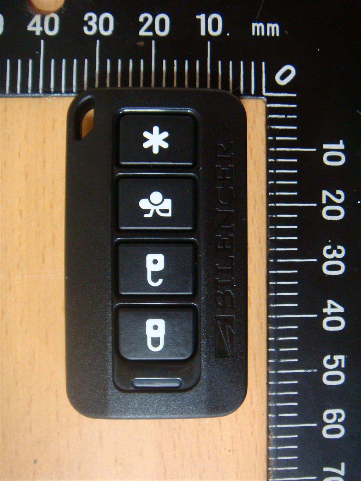
Registration number: W6M20707-8272-P-15 FCC ID: H5OT35 ETS Product Service (Taiwan) Co., Ltd. appendix page 39 of 45 External Photos Registration number: W6M20707-8272-P-15 FCC ID: H5OT35 ETS Product Service (Taiwan) Co., Ltd. appendix page 40 of 45
ID Label/Location Info
FCC ID: H5OT35 Model No.: XRO91 This device complies with Part 15 of the FCC Rules. Operation is subject to the following two conditions:(1) This device may not cause harmful interference, and (2) This device must accept any interference received, including interference that may cause undesired operation. 2.7 cm 2 cm
Internal Photos
Registration number: W6M20707-8272-P-15 FCC ID: H5OT35 ETS Product Service (Taiwan) Co., Ltd. appendix page 41 of 45 Internal Photos Registration number: W6M20707-8272-P-15 FCC ID: H5OT35 ETS Product Service (Taiwan) Co., Ltd. appendix page 42 of 45 Registration number: W6M20707-8272-P-15 FCC ID: H5OT35 ETS Product Service (Taiwan) Co., Ltd. appendix page 43 of 45 Registration number: W6M20707-8272-P-15 FCC ID: H5OT35 ETS Product Service (Taiwan) Co., Ltd. appendix page 44 of 45
Test Report
of Applicant: Advance Security Inc. Address: 3F, 48 Ta-An Street, Hsi-Chih Taipei Hsien, Taiwan R.O.C. Tested and Prepared by ETS Product Service (Taiwan) Co., Ltd. FCC Registration No.: 930600 Industry Canada filed test laboratory Reg. No. IC 5679 A2LA Accredited No.: 2300.01 PTCRB Accredited Type Certification Test House FCC ID: H5OT35 Report No.: W6M20707-8272-P-15 6F, NO. 58, LANE 188, RUEY-KUANG RD., NEIHU TAIPEI 114, TAIWAN, R.O.C. TEL: 886-2-66068877 FAX: 886-2-66068879 E-mail: [email protected] FCC TEST REPORT for Remote Control Model No.: XRO91 Registration number: W6M20707-8272-P-15 FCC ID : H5OT35 ETS Product Service (Taiwan) Co., Ltd. Page 1 of 37 TABLE OF CONTENTS 1 GENERAL INFORMATION ...................................................................................................... 2 1.1 Notes .................................................................................................................................... 2 1.2 Testing laboratory ................................................................................................................ 3 1.2.1 Location .......................................................................................................................3 1.2.2 Details of accreditation status ..................................................................................... 3 1.3 Details of approval holder.................................................................................................... 3 1.4 Application details ............................................................................................................... 4 1.5 General information of Test item......................................................................................... 4 1.6 Test standards ...................................................................................................................... 5 2 TECHNICAL TEST .................................................................................................................... 6 2.1 Summary of test results........................................................................................................ 6 2.2 Test environment ................................................................................................................. 6 2.3 Test Equipment List ............................................................................................................. 7 2.4 General Test Procedure........................................................................................................ 9 3 TEST RESULTS (ENCLOSURE) ............................................................................................ 11 3.1 Peak Output Power (transmitter) ....................................................................................... 12 3.2 Equivalent isotropic radiated power .................................................................................. 14 3.3 RF Exposure Compliance Requirements ........................................................................... 14 3.4 Out of Band Radiated Emissions ....................................................................................... 14 3.5 Transmitter Radiated Emissions in restricted Bands ......................................................... 15 3.6 Spurious emissions (tx)...................................................................................................... 16 3.7 Carrier Frequency Separation ............................................................................................ 28 3.8 Number of Hopping Frequencies....................................................................................... 29 3.8.1 Pseudorandom Frequency Hopping Sequence .......................................................... 30 3.8.2 Coordination of hopping sequences to other transmitters......................................... 30 3.8.3 System Receiver Hopping Capability ........................................................................ 30 3.8.4 Equal Hopping Frequency Use.................................................................................. 30 3.9 Time of Occupancy (Dwell Time) ..................................................................................... 31 3.10 20dB Bandwidth ................................................................................................................ 33 3.10.1 System Receiver Input Bandwidth.............................................................................. 33 3.11 Band-edge Compliance of RF Emissions .......................................................................... 34 3.12 Radiated Emissions from Receiver Section of Transceiver............................................... 35 3.13 Power Line Conducted Emission....................................................................................... 36 APPENDIX...................................................................................................... 37 Registration number: W6M20707-8272-P-15 FCC ID : H5OT35 ETS Product Service (Taiwan) Co., Ltd. Page 2 of 37 1 General Information 1.1 Notes The purpose of conformity testing is to increase the probability of adherence to the essential requirements or conformity specifications, as appropriate. The complexity of the technical specifications, however, means that full and thorough testing is impractical for both technical and economic reasons. Furthermore, there is no guarantee that a test sample which has Passed all the relevant tests conforms to a specification. Neither is there any guarantee that such a test sample will interwork with other genuinely open systems. The existence of the tests nevertheless provides the confidence that the test sample possesses the qualities as maintained and that is performance generally conforms to representative cases of communications equipment. The test results of this test report relate exclusively to the item tested as specified in 1.5. The test report …
Text truncated - open the document above for the full version.
Test Report
Registration number: W6M20707-8272-P-15 FCC ID : H5OT35 ETS Product Service (Taiwan) Co., Ltd. Page 25 of 37 Registration number: W6M20707-8272-P-15 FCC ID : H5OT35 ETS Product Service (Taiwan) Co., Ltd. Page 26 of 37 Registration number: W6M20707-8272-P-15 FCC ID : H5OT35 ETS Product Service (Taiwan) Co., Ltd. Page 27 of 37 Note 1. Correction Factor = Antenna factor + Cable loss - Preamplifier 2. The formula of measured value as: Test Result = Reading + Correction Factor 3. All not in the table noted test results are more than 20 dB below the relevant limits. All other not noted test plots do not contain significant test results in relation to the limits. TEST RESULT (Transmitter): The unit DOES meet the FCC requirements. Test equipment used: ETSTW-RE 003 ETSTW-RE 004 ETSTW-RE 017 ETSTW-RE 028 ETSTW-RE 029 ETSTW-RE 030 ETSTW-RE 042 ETSTW-RE 043 ETSTW-RE 044 ETSTW-RE 064 Registration number: W6M20707-8272-P-15 FCC ID : H5OT35 ETS Product Service (Taiwan) Co., Ltd. Page 28 of 37 3.7 Carrier Frequency Separation Carrier Frequency Separation was measured with modulation (declared by manufacturer). According to FCC rules part 15 subpart C §15.247 frequency hopping systems shall have hopping channel carrier frequencies separated by a minimum of 25 kHz or 20 dB bandwidth of the hopping channel, whichever is greater. Channel Separation Test conditions Channel 0 Channel 0+1 T nom = 23°C V nom = 6 V 498.968512365 kHz Channel Separation Test conditions Channel 12 Channel 12+1 T nom = 23°C V nom = 6 V 498.996558962 kHz Channel Separation Test conditions Channel 24 Channel 24+1 T nom = 23°C V nom = 6 V 498.965896549 kHz Limits: Limits Frequency Range MHz 20 dB bandwidth < 25 kHz 20 dB bandwidth > 25 kHz 902-928 25 kHz 20 dB bandwidth 2400-2483.5 5725-5850.0 25 kHz 20 dB bandwidth Test equipment used: ETSTW-RE 003 ETSTW-RE 004 ETSTW-RE 055 ETSTW-RE 064 Explanation: See attached diagram as appendix. Registration number: W6M20707-8272-P-15 FCC ID : H5OT35 ETS Product Service (Taiwan) Co., Ltd. Page 29 of 37 3.8 Number of Hopping Frequencies According to FCC rules part 15 subpart C §15.247 frequency hopping systems operating in the 2400- 2483.5 MHz band shall use at least 15 hopping frequencies. Frequency hopping systems in 5725-5850 MHz bands shall use least 75 hopping frequencies. For frequency hopping systems operating in the 902-928 MHz band: if the 20dB bandwidth of the hopping channel is less than 250 kHz, the system shall use at least 50 hopping frequencies; if the 20dB bandwidth of the hopping channel 250 kHz or greater, the system shall use at least 25 hopping frequencies. Test conditions Operating Mode Number of Channels T nom = 23°C V nom = 6 V normal transmitting 25 T nom = 23°C V nom = 6 V Inquiry mode -- Limits: Limit 20dB Bandwidth Frequency Range MHz ≤ 1MHz 20dB Bandwidth < 250 kHz 20dB Bandwidth ≥ 250 kHz 902-928 MHz ≥ 50 ≥ 25 2400-2483.5 ≥ 15 ≥ 15 5725-5850.0 MHz ≥ 75 Test equipment used: ETSTW-RE 003 ETSTW-RE 004 ETSTW-RE 055 ETSTW-RE 064 Explanation: See attached diagrams as appendix. Registration number: W6M20707-8272-P-15 FCC ID : H5OT35 ETS Product Service (Taiwan) Co., Ltd. Page 30 of 37 3.8.1 Pseudorandom Frequency Hopping Sequence This FHSS transmitter is controlled by a microchip to generate the Pseudorandom Frequency Hopping Sequence. There are three hopping sequences listed below: Sequence A : 915.5, 914, 912.47, 910.5, 913.45, 911.5, 910, 909, 909.5, 911, 912.96, 914.5, 916.51, 916, 915, 917.6, 919.6, 921.77, 920.29, 918.11, 919.11, 921.29, 920.8, 918.62, 917.05 Sequence B : 921.29, 919.11, 917.6, 919.6, 918.11, 916, 914.5, 912.96, 910.5, 909, 911, 909.5, 911.5, 910, 912.47, 914, 913.45, 915, 917.05, 915.5, 916.51, 918.62, 920.8, 921.77, 920.29 Sequence C : 913.45, 915.5, 918.11, 920.29, 920.8, 918.62, 916.51, 915, 912.96, 911, 910, 911.5, 909.5, 909, 910.5, 912.47, 914, 916, 917.6, 919.6, 921.77, 921.29, 919.11, 917.05, 914.5 3.8.2 Coordination of hopping sequences to other transmitters This transmitter does not have the ability of being coordinated with other FHSS system for as soon as the transmitter is in operation, the hopping frequency will follow the selected hopping sequence to transmit independently and no coordination is possible. Especially, this transmitter is used as a duplex car alarm system, so no coordination of hopping frequency is required. 3.8.3 System Receiver Hopping Capability There are two steps to make the receiver to shift the frequencies in synchronization with the transmitted signals: First, the Transmitter will emit a preamble signal of 50 ms and the receiver will scan this signal by 2ms sweeping until the preamble signal is caught. Second, the preamble signal is coded with the information of hopping sequence and the next transmitting frequency, so the receiver will be able to shift the receiving frequencies in synchronization with the transmitted signals. 3.8.4 Equal Hopping Frequency Use Due to each hopping frequency will be transmitted in accordance to the frequency tables described above, there is no any frequency will be able to hop more times than others. Therefore each frequency will be used equally. Registration number: W6M20707-8272-P-15 FCC ID : H5OT35 ETS Product Service (Taiwan) Co., Ltd. Page 31 of 37 3.9 Time of Occupancy (Dwell Time) Frequency hopping systems operating in the 5725-5850 MHz band shall use an average time of occupancy on any frequency not greater than 0.4 seconds within a 30 second period. In 2400-2483,5 MHz band the average time of occupancy on any channel shall not be greater than 0,4 seconds multiplied by the number of hopping channels employed. For frequency hopping systems operating in the 902-928 MHz band: if the 20dB bandwidth of the hopping channel is less than 250 kHz, the average time of occupancy on any frequency shall not greater than 0.4 seconds within a 20 second period; if the 20dB bandwidth of the hopping channel is 250 kHz or greater, the average time of occupancy on any frequency shall not be greate…
Text truncated - open the document above for the full version.
Test Setup Photos
Registration number: W6M20707-8272-P-15 FCC ID: H5OT35 ETS Product Service (Taiwan) Co., Ltd. appendix page 45 of 45 Set Up Photo of Radiated Emission
Contact Information
Applicant
Michael Chen(SAL)
Technical Contact
ETS Product Service (Taiwan) Co., Ltd.Steven Chuang
[email protected]+886-2-6606-8877
6F., No. 58, Lane 188, Ruey Kuang Road, Neihu · Taipei · Taiwan
Test Firm
Worldwide Testing Services (Taiwan) Co. Ltd.Chang Tse-Ming
Technical Specifications
| # | Rule Parts | Frequency Range | Power Output |
|---|---|---|---|
| 1 | 15C | 909 MHz - 921.778 MHz | 9.59 mW |
Other Applications from Advance Security Inc
H5OT62
Dec 11, 2015Remote Control
Equipment Class
DSC - Part 15 Security/Remote Control Transmitter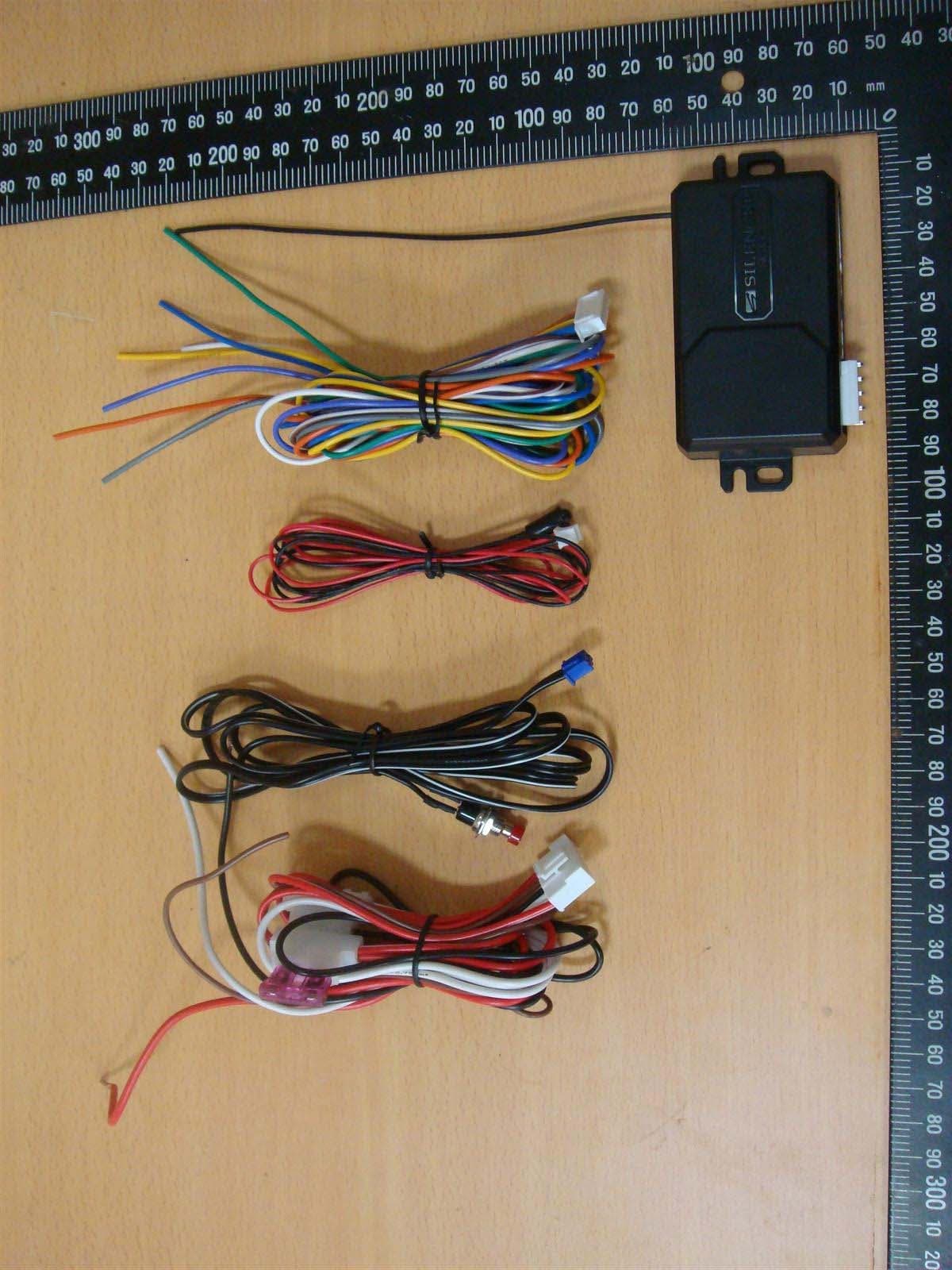
H5OR57
Dec 11, 2015Remote Control
Equipment Class
CYY - Communications Receiver used w/Pt 15 Transmitter
H5OTR64
Oct 22, 2015Remote Control
Equipment Class
DSS - Part 15 Spread Spectrum Transmitter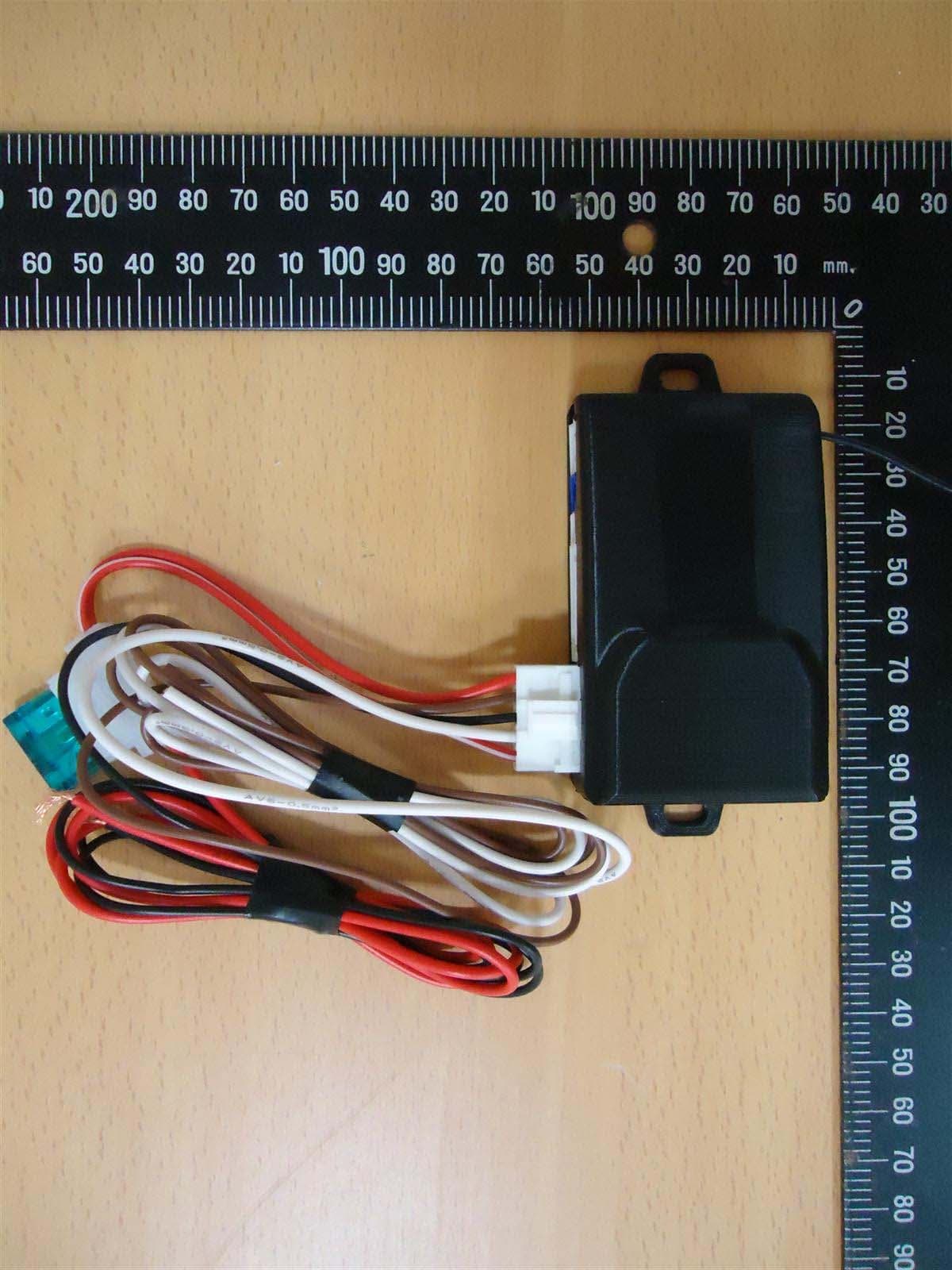
H5OR56
Sep 10, 2015Remote Control
Equipment Class
CYY - Communications Receiver used w/Pt 15 Transmitter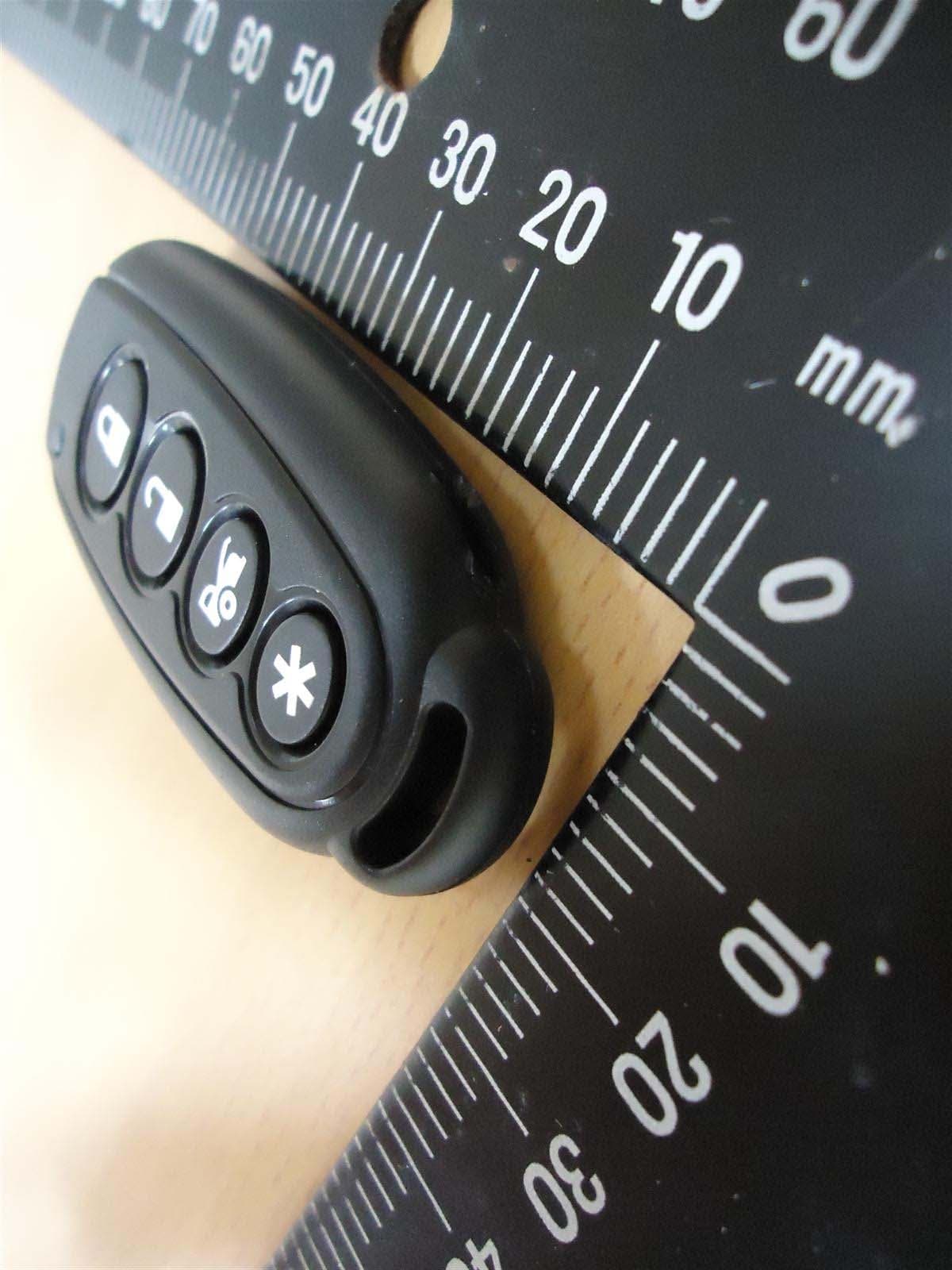
H5OT61
Sep 07, 2015Remote Control
Equipment Class
DSC - Part 15 Security/Remote Control Transmitter