H5OTR14Car Alarm Transceiver
Advance Security Inc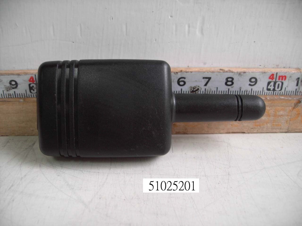
Click to zoom
Application Details
- Equipment Class
- DSR - Part 15 Remote Control/Security Device Transceiver
- Date of Grant
- Jan 09, 2006
- Application Purpose
- Original Equipment
- Date of Application
- Jan 09, 2006
- Equipment Note
- Car Alarm Transceiver
- Frequency Range
- 433.92000000 - 433.92000000
- Company
- Advance Security Inc
- Country
- Taiwan
Documents & Files
Document Text
Text extracted from the exhibit documents filed with the FCC. Open a document above to read the original.
Users Manual
MODEL TRX72 REMOTE ENGINE STARTER WITH ALARM SYSTEM INSTALLATION MANUAL INSTALLATION DIAGRAM H 6 3 Pin White H 1 6 Pin White H 8 4 Pin Orange H 7 8 Pin Black VALET SWITCH H 5 6 Pin White H 4 2 Pin Blue Dual Zone Shock Sensor 5. Pink: Ignition 2 output 2. Red: +12V Input 3. Red: +12V Input 4. Yellow: Ignition 1 output 1. Violet: Starter Output 20A Fuse 20A Fuse 6. Brown: ACC/Heater Output H7 8 Pin Black Connector for Input Connection H5 6 Pin White Connector for Output Connection 3. G r ee n: ( - ) Lock P u l s e. O r ( + ) U nl ock P u l s 1. B l ue : ( -) U n l o ck P u l s e. O r ( + ) Lock P u l s e H 3 2 Pin White LED Indicator H 9 4 Pin Black Two Way Transceive r Antenna H 2 5 Pin White 1. Red / White: Parking Light Relay Power input 2. White: Parking Light Relay Output 3. Black: Ground to Vehicle Frame 4. Brown: Positive Output to Siren 5. Red: +12V Input 10A Fuse 3A Fuse 1 #H5 6 PIN WHITE CONNECTOR FOR OUTPUT CONNECTION 1. White Wire: (-) 200 mA Programmable output Dome Light Control Output (Factory Default setting) Or Horn Output Or Factory Security Rearm Signal Output Or Ground Out put During Start (Crank). 6. Orange Wire: (-) 500mA Grounded Output When Armed 4. Gray Wire: (-) 200 mA Channel 3 (Trunk) Output 2. Yellow Wire: (-) 200 mA Ignition 3 Control Output 5. Pink Wire: (-) 200 mA Programmable output 2-Step Door Unlock Output (Factory Default setting) Or Factory Security Disarm Signal Output Or Start Status (Shock Sensor Bypass Control) Output 3. Black / Green Wire: (-) 200 mA Time Control Channel 4 Output #H7. 8 PIN BLACK CONNECTOR FOR INPUT CONNECTION: 2. Green Wire: Zone 3 Negative Door Pin Trigger Input: 1. Blue Wire: Zone 2 Instant Trigger Ground Input 3. Violet Wire: Zone 3 Positive Door Pin Trigger 7. White/Violet Wire: ( + ) Positive Safety Shut Down Input for Brake switch. 6. Black/White Wire: ( - ) Neutral Safety Switch Input & ( - ) Remote Start Toggle Switch Input 8. White/Red Wire: Tach. Signal Input +12V 5. White/Black Wire: ( - ) Negative Safety Shut Down Input for Hood pin switch IMPORTANT NOTE: Directly connect the H7/6 BLACK/WHITE wire to the “GROUND” when this wire is not used. +12V 4. White/Blue Wire: (-) Instant Start and Turn Off Input. 2 INTRODUCTION INSTALLER WARNINGS This Remote Starter with Alarm System is designed to be installed on fuel injected vehicles ONLY. For automatic transmission vehicle, this system must be installed and wired through a safety switch it will not start in any forward or reverse gear. Some automatic transmission vehicle [mainly older GM vehicles with a purple starter wire] have a mechanical-type park safety switch instead of electrical safety switch. The mechanical type does not interrupt the starter circuit when the transmission is any gear and does not offer the 100% level of safety required for remote starting purposes. Therefore, our system should never be installed on any vehicle that uses a mechanical type park safety switch. For automatic transmission vehicle, once you install this system, you must verify that the vehicle will not start any forward or reverse gear. Regardless of the type of vehicle. Read operation manual for operating and programming routine. Do not install any component near the brake, gas pedal or steering linkage. Some vehicles have a factory installed transponder immobilizer system that can severely complicate the installation. There is possibility that this system can not be installed on some immobilizer equipped vehicles. Most vehicles have an SRS air bag system. Use extreme care and do not probe any wires of the SRS system. Disconnect the car battery before connecting work on the vehicle. Check behind panels before drilling any holes. Ensure that no wiring harness or other components are located behind the panels that would otherwise be damaged. Use conventional crimp lock, bullet on any wiring. Poor wiring, i.e. taped joints will possibly introduce unreliability into the alarm system and may result in false alarms or incorrect operation. Install wiring neatly under carpets or behind trim to prevent possible damage to wires. For the wire operates the current more than 10A. We suggest soldering all connection point. Do not use crimp lock type connectors or wire nuts. WIRING Keep wiring away from moving engine parts, exhaust pipes and high-tension cable. Tape wires that pass through holes on the firewall to prevent fraying. Watches out sharp edges that may damage wires and causes short circuit. CAUTION: Do not connect the wire harness to the control module until all wiring to vehicle is complete. H1: 6 PIN HEAVY GAUGE WIRING CONNECTION: Remember that the system does to start a vehicle is duplicate the functions of the ignition key switch! Below, we will explain the three basic functions of the ignition switch. Since this installation will require analysis of the ignition switch functions, we recommend making the three connections below at the ignition switch harness directly. H1/1. Violet Wire – Starter Output Careful consideration for the connection of this wire must be made to prevent the vehicle from starting while in gear. Understanding the difference between a mechanical and an electrical Neutral Start Switch will allow you to properly identify the circuit and select the correct installation method. In addition you will realize why the connection of the safety wire is required for all mechanical switch configurations. Failure to make this connection properly can result in personal injury and property damage. In all installations it is the responsibility of the installing technician to test the remote start unit and assure that the vehicle can not start via RF control in any gear selection other than park or neutral. In both mechanical and electrical neutral start switch configurations, the connection of the VIOLET wire will be made to the low current start solenoid wire of the ignition switch harness. This wire have +12 volts when the ignition switch is turned to the …
Text truncated - open the document above for the full version.
Block Diagram
1 2 3 4 ABCD 4 3 2 1 D CBA Title Number Revision Size A4 Date: 19-Oct-2005 Sheet of File: C:\ddb-work\CKT.ddb Drawn By:
Cover Letter(s)
ADVANCED ADVANCE SECURITY INC. 3F, 48 Ta An Street, Hsi Chih, Phone : (886-2) 8648-1688 E-mail : [email protected] Taipei Hsien, TAIWAN R.O.C. Telexfax : (886-2) 8648-1689 Date: August 18, 2005 Compliance Certification Services Certification Division 561F Monterey Road Morgan Hill, CA 95037 To whom it may concern: We, the undersigned, hereby authorize the Testing Division of Compliance Engineering Services, Inc., d.b.a. Compliance Certification Services and hereafter referred to as CCS, to act on our behalf in all manners relating to application for equipment authorization, including signing of all documents relating to these matters. Any and all acts carried out by CCS on our behalf shall have the same effect as acts of our own. We, the undersigned, hereby certify that we are not subject to a denial of federal benefits, that includes FCC benefits, pursuant to Section 5301 of the Anti-Drug Abuse Act of 1988, 21 U.S.C. 853(a). In authorizing CCS Testing Division as our agent, we still recognize that we are responsible to: comply with the relevant provisions of the certification program; b) make all necessary arrangements for the conduct of the evaluation, including provision for examining documentation and access to all areas, records (including internal audit reports) and personnel for the purposes of evaluation (e.g. testing, inspection, assessment, surveillance, reassessment) and resolution of complaints; c) make claims regarding certification only in respect of the scope for which certification has been granted; d) do not use our product certification in such a manner as to bring the Certification Division into disrepute and not make any statement regarding our product certification which the Certification Division may consider misleading or unauthorized; e) upon suspension or cancellation of certification, discontinue use of all advertising matter that contains any reference thereto and return any certification documents as required by the Certification Division; f) use certification only to indicate the products are certified as being in conformity with specified standards; g) endeavor to ensure that no certificate or report nor any part thereof is used in a misleading manner; h) ensure that any reference to our product certification in communication media such as documents, brochures or advertising, complies with the requirements of the Certification Division; i) keep a record of all complaints made known to the us relating to the product’s compliance with requirements of the relevant standard and to make these records available to the Certification Division when requested; j) take appropriate action with respect to such complaints and any deficiencies found in products or services that affect compliance with the requirements for certification; k) document the actions taken. This authorization is valid until further written notice from the applicant. ADVANCE SECURITY INC. TED LIN SALES MANAGER REMARK: 1. This authorization letter will be sent along with your application when filing with the Certification Division. 2. Please follow the format and type it on company letterhead and send original to us.
External Photos
Compliance Certification Services Inc. Report No.: 51025201 Date of Issue: January 6, 2006 Page 1 Total Page: 5 Rev. 00 PHOTOGRAPHS OF EUT Compliance Certification Services Inc. Report No.: 51025201 Date of Issue: January 6, 2006 Page 2 Rev. 00 Compliance Certification Services Inc. Report No.: 51025201 Date of Issue: January 6, 2006 Page 3 Rev. 00
ID Label/Location Info
FCC ID LABEL FORMAT AND LOCATION Applicant: Advance Security Inc. FCC ID: H5OTR14 FCC ID: H5OTR14 This device complies with part 15 of the FCC Rules. Operation is subject to the following two conditions: (1) This device may not cause harmful interference, and (2) this device must accept any interference received, including interference that may cause undesired operation. FCC ID LABEL AREA
Internal Photos
Compliance Certification Services Inc. Report No.: 51025201 Date of Issue: January 6, 2006 Page 4 Rev. 00 Compliance Certification Services Inc. Report No.: 51025201 Date of Issue: January 6, 2006 Page 5 Rev. 00
Operational Description
(TRX72) Operational Description The 2 way pager is a low-powered transmitter device used in monitoring the automobile security status as well as in remotely engine start system and other optional features .Its features and functions are described in the separate attached sheet. The transmission is powered by DC 12V and works on 433.92 Mhz single fixed frequency. Details of circuit diagram and its block diagramare are shown on the attached sheets. sgnals and modulate the carrier signal. The carrier signal is generated by a crystal oscillator/ amplifter circuit composed of a 433.92 Mh crystal and a npn transmitter. The modulated output of RF amplifier stage is coupled to the coil. The module will be transmitting when the RF module data input is Hi; the module will stop transmitting when the RF module data input is Low. The single is controlled by the CPU control data input inside the control unit. Normally the transmitting time is about 0.6 seconds, the maximum is lasting for 4.5seconds. The automobile’s sensor will trigger the digital control signals and modulate the carrier signal. The carrier signal is generated by a crystal oscillator/ amplifter circuit composed of a 433.92 Mh crystal and a npn transmitter. The modulated output of RF amplifier stage is coupled to the coil. All the tuning and verification are done by manufacturer during the production process and no adjustment is allowed by any consumer. No external ground is needed in such device. This device complies with part 15 of the FCC rules. Operation is subject to the following two conditions:- (1) This device may not cause harmful interference. (2) This device must accept any interference received : including interference that may cause undesired operation. Note: The manufacturer is not responsible for any radio of TV interference caused by unauthorized modification to this equipment. Such modification could void the user’ authority to operate the equipment.
Test Report
Compliance Certification Services Inc. Report No.: 51025201-RP1 FCC ID: H5OTR14 Date of Issue: January 6, 2006 Page 1 of 20 Rev. 00 FCC ELECTROMAGNETIC EMISSIONS COMPLIANCE REPORT CERTIFICATION TO FCC PART 15 REQUIREMENTS For INTENTIONAL RADIATOR of Car Alarm Transceiver FCC ID Number : H5OTR14 Trade Name : Advance Security Inc. Model Number : TRX72 Agency Series : N/A Report Number : 51025201-RP1 Date : January 6, 2006 Issued to Advance Security Inc. 3F, 48 Ta An Street, Hsi Chih, Taipei Hsien, TAIWAN R.O.C. Issued by Compliance Certification Services Inc. Hsintien Lab. No. 165, Chunghsen Road, Hsintien City Taipei Hsien, Taiwan TEL: (02) 2217-0894 FAX: (02) 2217-1029 Note: This report shall not be reproduced except in full, without the written approval of Compliance Certification Services Inc. Ltd. This document may be altered or revised by Compliance Certification Services Inc. personnel only, and shall be noted in the revision section of the document. Compliance Certification Services Inc. Report No.: 51025201-RP1 FCC ID: H5OTR14 Date of Issue: January 6, 2006 Page 2 Rev. 00 TABLE OF CONTENTS 1. VERIFICATION OF COMPLIANCE .............................................................. 3 2. PRODUCT DESCRIPTION ............................................................................... 4 3. TEST FACILITY ................................................................................................. 4 4. MEASUREMENT STANDARDS ...................................................................... 4 5. TEST METHODLOGY....................................................................................... 4 6. MEASUREMENT EQUIPMENT USED.......................................................... 5 7. POWERLINE RFI LIMIT.................................................................................. 5 8. RADIATED EMISSION LIMITS...................................................................... 6 9. SYSTEM TEST CONFIGURATION................................................................ 6 10. TEST PROCEDURE ........................................................................................... 8 11. EQUIPMENT MODIFICATIONS .................................................................... 9 12. TEST RESULT ................................................................................................... 10 12.1. MAXIMUM MODULATION PERCENTAGE (M%).............................. 10 12.2. THE EMISSIONS BANDWIDTH................................................................ 10 APPENDIX I TEST DATA ...................................................................................... 11 Compliance Certification Services Inc. Report No.: 51025201-RP1 FCC ID: H5OTR14 Date of Issue: January 6, 2006 Page 3 Rev. 00 1. VERIFICATION OF COMPLIANCE COMPANY NAME : Advance Security Inc. 3F, 48 Ta An Street, Hsi Chih, Taipei Hsien, TAIWAN R.O.C. CONTACT PERSON : Michael Chen / President TELEPHONE NO. : 886-2-8648-1688 EUT DESCRIPTION : Car Alarm Transceiver MODEL NAME/NUMBER : TRX72 FCC ID : H5OTR14 DATE TESTED : October 29, 2005 ~ January 4, 2006 REPORT NUMBER : 51025201-RP1 TYPE OF EQUIPMENT SECURITY EQUIPMENT (INTENTIONAL RADIATOR) EQUIPMENT TYPE 433.92 MHz Car Alarm Transceiver MEASUREMENT PROCEDURE ANSI 63.4 / 2003 LIMIT TYPE CERTIFICATION FCC RULE CFR 47, PART 15 The above equipment was tested by Compliance Certification Services Inc. for compliance with the requirements set forth in the FCC CFR 47, PART 15. The results of testing in this report apply to the product/system which was tested only. Other similar equipment will not necessarily produce the same results due to production tolerance and measurement uncertainties. Warning: This document reports conditions under which testing was conducted and results of tests performed. This document may not be altered or revised in any way unless done so by Compliance Certification Services Inc. and all revisions are duly noted in the revisions section. Any alteration of this document not carried out by Compliance Certification Services Inc. will constitute fraud and shall nullify the document. Approved by: Reviewed by: Compliance Certification Services Inc. Report No.: 51025201-RP1 FCC ID: H5OTR14 Date of Issue: January 6, 2006 Page 4 Rev. 00 2. PRODUCT DESCRIPTION Fundamental Frequency 433.92 MHz Power Source 12VDC Transmitting Time Periodic < 5 seconds Associated Transceiver FCC ID: H5OTR12 3. TEST FACILITY The open area test sites and conducted measurement facilities used to collect the radiated data are located at No. 165, Chunghsen Road, Hsintien City, Taipei Hsien, Taiwan, R.O.C. The sites are constructed in conformance with the requirements of ANSI C63.7, ANSI C63.4 and CISPR Publication 22. 4. MEASUREMENT STANDARDS The site is constructed and calibrated in conformance with the requirements of ANSI C63.4/2003. 5. TEST METHODOLOGY For an intentional radiator, the spectrum shall be investigated from the lowest radio frequency signal generated in the device, without going below 9 KHz, up to at least the tenth harmonic of the highest fundamental frequency or to 40 GHz, whichever is lower. (CFR 47 Section 15.33) Compliance Certification Services Inc. Report No.: 51025201-RP1 FCC ID: H5OTR14 Date of Issue: January 6, 2006 Page 5 Rev. 00 6. MEASUREMENT EQUIPMENT USED Open Area Test Site # H Name of Equipment ManufacturerModel Serial Number Calibration Due SITE NSA CCS H Site N/A 10/09/2006 MEASURE RECEIVER SCHAFFNER SCR3501 341 09/07/2006 SPECTRUM ANALYZER ADVANTEST R3132 120900002 No Calibration Required ANTENNA SCHAFFNER CBL 6112B 2801 09/23/2006 AMPLIFIER SCHAFFNER CPA9231A 3613 10/08/2006 CABLE SUHNER RG 214 N-TYPE#H2 12/02/2006 THERMO- HYGRO METER TFA N/A NO.1 12/25/2006 EMC ANALYZER (100Hz-22GHz) HP 8566B 2937A06102 06/30/2006 ANTENNA (1-18GHz) EMCO 3115 5761 01/17/2006 AMPLIFIER (1-18GHz) HP 8449B 3008A01266 02/16/2006 CABLE (1-18GHz) JYEBAO LL142 SMA#RS1&2 02/16/2006 CABLE (1-18GHz) JYEBAO LL142 SMA#C1 04/28/2006 Remark: Each piece of…
Text truncated - open the document above for the full version.
Test Setup Photos
Compliance Certification Services Inc. Report No.: 51025201-RP1 FCC ID: H5OTR14 Date of Issue: January 6, 2006 Page 6 Rev. 00 8. RADIATED EMISSION LIMITS GENERAL REQUIREMENTS SECTION 15.209 RESTRICTED BANDS OF OPERATION SECTION 15.205 PERIODIC OPERATION IN THE BAND 40.66 -40.70 MHz AND ABOVE 70 MHz. SECTION 15.231 RECEIVER MODE SECTION 15.109 9. SYSTEM TEST CONFIGURATION Use a block of foam and combined it with EUT wrapping rubber band around it. This way it can test X, Y and Z axis. To activate continuous transmitting & receiving, place a small plastic block between rubber band and EUT push button. Radiated Open Site Test Set-up Compliance Certification Services Inc. Report No.: 51025201-RP1 FCC ID: H5OTR14 Date of Issue: January 6, 2006 Page 7 Rev. 00 Radiated Open Site Test Set-Up (Receiver Mode)
Contact Information
Applicant
Michael Chen(SAL)
Test Firm
Compliance Certification Services Inc.Kurt Chen
Technical Specifications
| # | Rule Parts | Frequency Range | Power Output |
|---|---|---|---|
| 1 | 15.231 | 433.92 MHz - 433.92 MHz | - |
Other Applications from Advance Security Inc
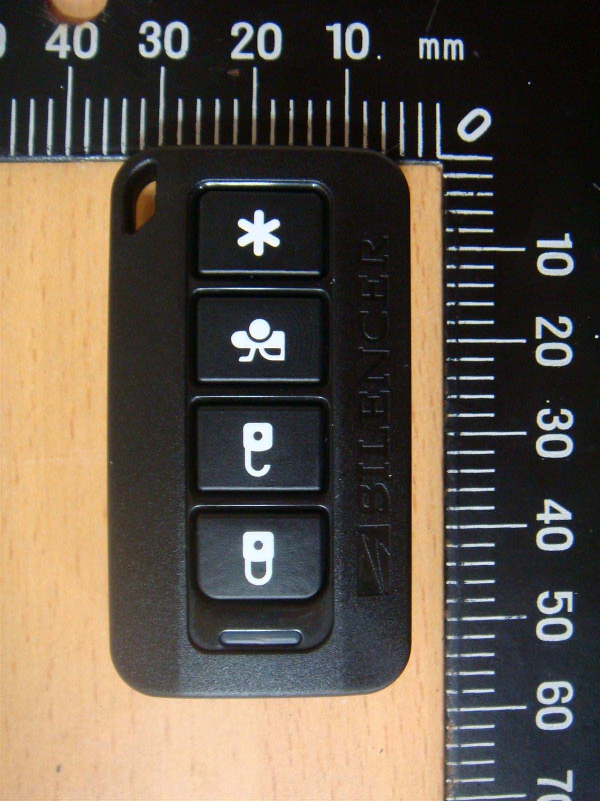
H5OT62
Dec 11, 2015Remote Control
Equipment Class
DSC - Part 15 Security/Remote Control Transmitter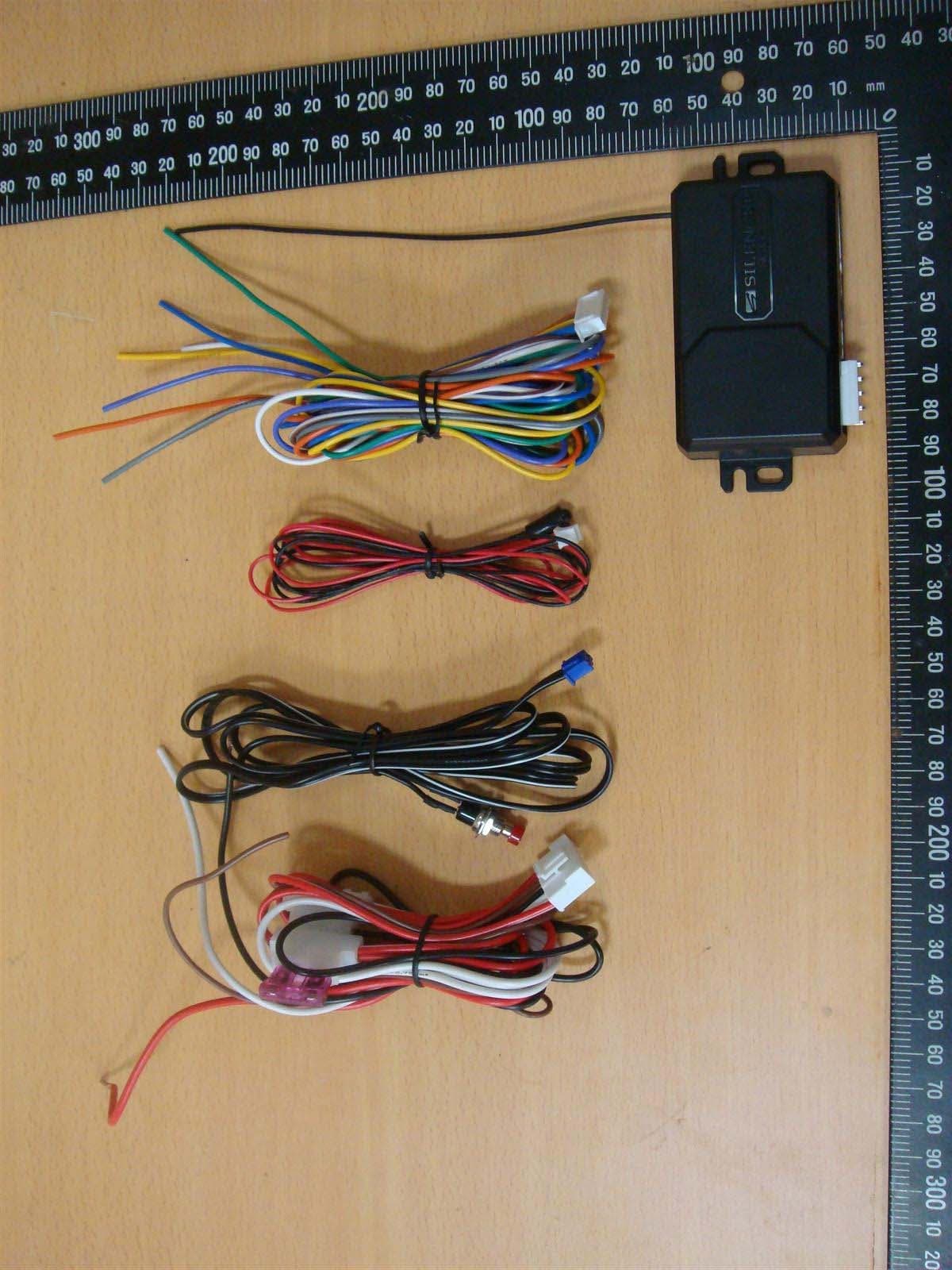
H5OR57
Dec 11, 2015Remote Control
Equipment Class
CYY - Communications Receiver used w/Pt 15 Transmitter
H5OTR64
Oct 22, 2015Remote Control
Equipment Class
DSS - Part 15 Spread Spectrum Transmitter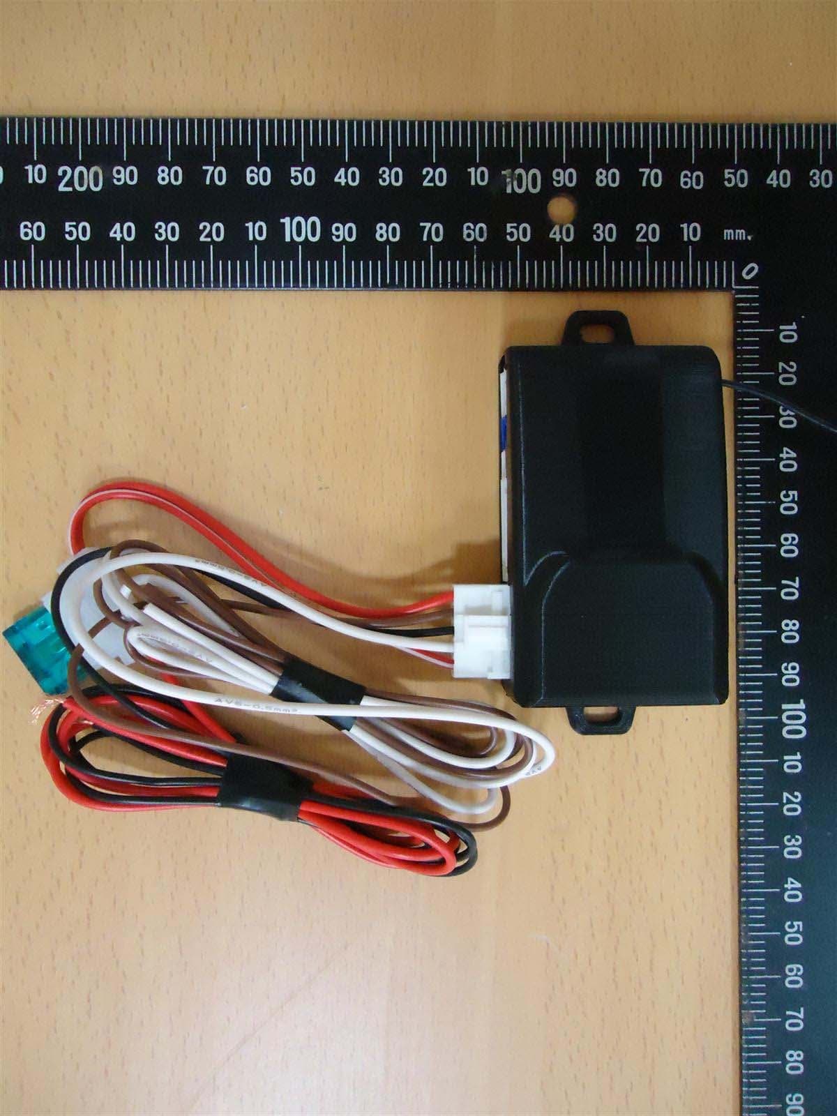
H5OR56
Sep 10, 2015Remote Control
Equipment Class
CYY - Communications Receiver used w/Pt 15 Transmitter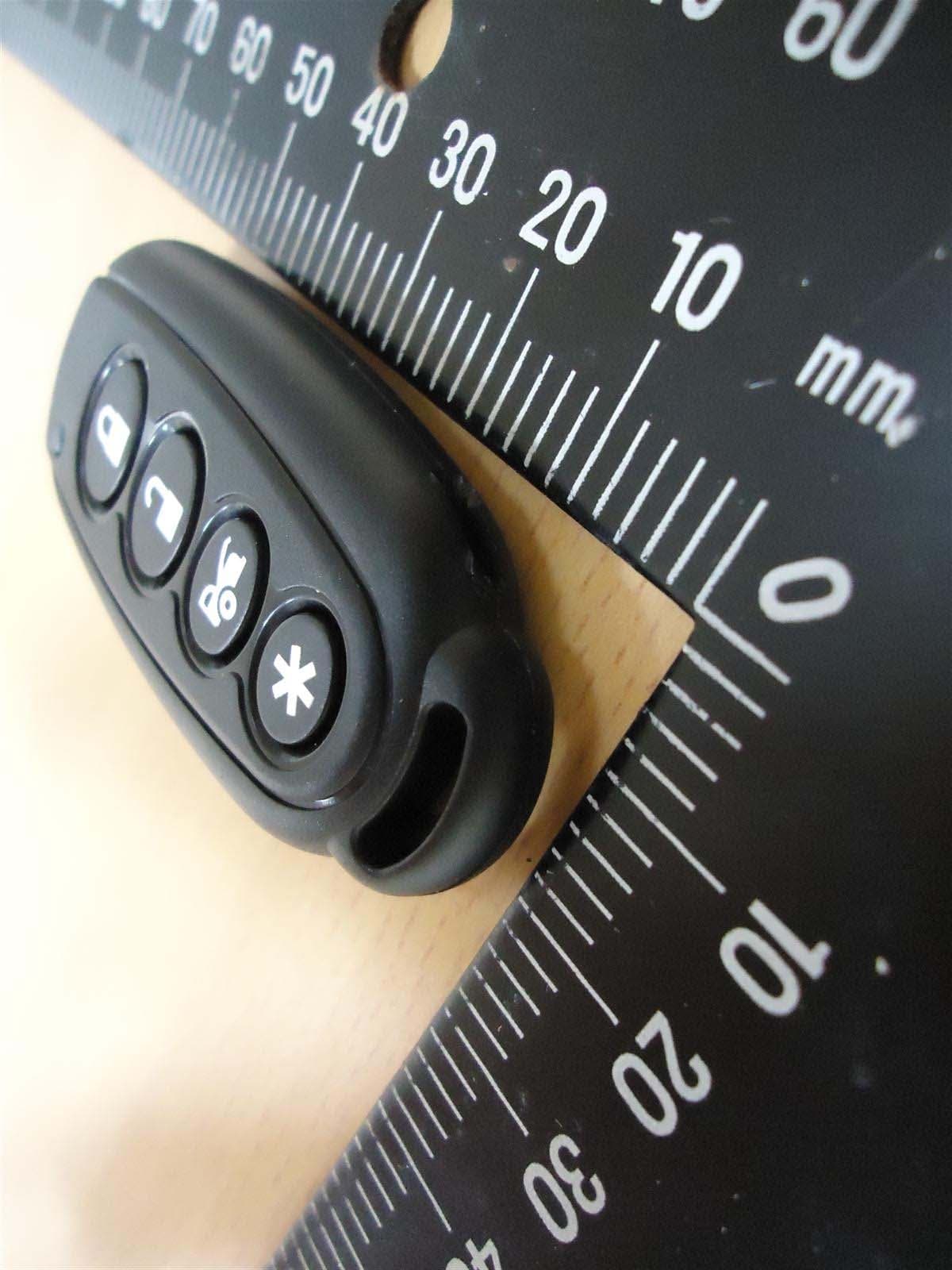
H5OT61
Sep 07, 2015Remote Control
Equipment Class
DSC - Part 15 Security/Remote Control Transmitter