H5OTR21Car Alarm Transceiver
Advance Security Inc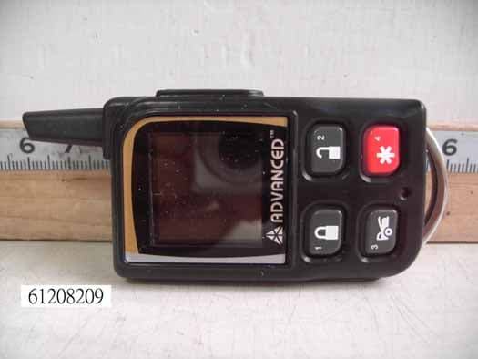
Click to zoom
Application Details
- Equipment Class
- DSR - Part 15 Remote Control/Security Device Transceiver
- Date of Grant
- Jan 28, 2007
- Application Purpose
- Original Equipment
- Date of Application
- Jan 28, 2007
- Equipment Note
- Car Alarm Transceiver
- Frequency Range
- 915.00000000 - 915.00000000
- Company
- Advance Security Inc
- Country
- Taiwan
Documents & Files
Document Text
Text extracted from the exhibit documents filed with the FCC. Open a document above to read the original.
Users Manual
1 TRX970 OPERATION MANUAL 2 REMOTE TRANSCEIVER (TX) A. OLED DISPLAY I n case the remote transceiver malfunction, errors or freeze of display, it is recommended to reset your remote transceiver. switch OLED Display Engine Running Name of Transmitter switch button Antenna switch Button Button 1 Button Button 3 Button Button 2 Button Button 4 switch button Antenna Reset Hole Battery Level Car Jacking In – Range Indicator Door Lock Door Unlock Alarm Status Temperature Engine Running Melody Mode Timer Start Alert Alarm Count Down Timer Parking Timer Timer Vibration Mode Bypass Shock Sensor (Zone 4) 3 B. CHARGE THE BATTERY Power by built-in 3.7V lithium polymer battery, if the OLED screen display low battery or is flash, charge your remote transceiver. While the battery of the Remote Transceiver is under the battery charging, you can push the ” ” button to check charging condition. AC Power Supply The remote transceiver equipped AC POWER SUPPLY / AC ADAPTOR (Output Voltage: 4.2VDC – 5.5VDC and with same USB plug), then you can charge the battery indoors. While the battery of the Remote Transceiver is under charging. Push the button; the screen will display Battery charging. C. SELECT THE TRANSCEIVER’S BUTTON CONFIGURATION: 1. Spin up the Switch to select the transceiver button configuration you need and the OLED screen will display the transceiver button configuration you select. 2. Within 5 seconds press the button 1, 2, 3 or 4 to remote control “button configuration” you selected. Note: If 5 seconds of inactivity expired, or push the button, the transceiver button configuration mode will exit. Spin up the switch to the page 1 Spin up the switch to the page 2 Spin up the switch to the page 3 Spin up the switch to the page 4 Spin up the switch to the page 5 Spin up the switch to the page 6 Spin up the switch resume to main page. D. SELECT THE TRANSCEIVER FEATURES: 1. Spin down the Switch to select the transceiver feature you need and the OLED screen will display the features you select. 2. Press the button 1, 2, 3 or 4 once within 3 seconds after finished selection and the OLED screen will change the display alternatively. Note: If 5 seconds of inactivity expire, or push the button, the transceiver features program mode will exit. 4 Spin down the switch to the page 1 Spin down the switch to the page 2 Spin down the switch to the page 3 Spin down the switch to the page 4 Spin down the switch to the page 5 Spin down the switch to the page 6 Spin down the switch resume to main page. E- P1- 1. “BUTTON BI” SETTING: Example: Set the “Button Bi Disable”. It has a short “bi” sound while pressing the button of the remote transceiver Spin down the switch to the page 1 Press the button 1 and it will display previously setting Press the button 2 to change the setting Press the button and the setting is done. E- P1- 2. “BUTTON LOCK” SETTING: Example: Set the “Button Lock Enable”. Spin down the switch to the page 1 Press the button 2 and it will display previously setting Press the button 1 to change the setting Press the button and the setting is done. E- P1- 3. “MELODY / VIBRATION MODE” SETTING: Example: set the Vibration mode. Spin down the switch to the page 1 Press the button 3 and it will display previously setting Press the button 2 to change the setting Press the button and the setting is done also the icon will display on the OLED screen 5 E- P1- 4. “DEMO MODE”: Spin down the switch to the page 1 Press the button 4 to start Demo movie Demo movie playing Press the any Button to exit. E- P2- 1. “POWER SAVE” SETTING: Example set the “Power Save Enable”. While the power save mode, the LCD remote transceiver uses “0” current to save the battery power. Spin down the switch to the page 2 Press the button 1 and it will display previously setting. Press the button 1 to change the setting. Press the button and the setting is done. E- P2- 2. “PARKING METER” SETTING: Example set the “Parking Meter 30 min.. Note: When “parking meter” trigger presses any button to stop the beeper. Spin down the switch to the page 2 Press the button 2 Press the button 1 three times to set the parking timer to 30 minutes. Press the button to start the parking meter and the icon will flash on the main page. D- P2- 3. “PARKING AREA” SETTING: Example set the “Parking Area.” to “B120 Spin down the switch to the page 2 Press the button 3, it will display previously parking area Press the button 2 to clear the parking area, and the “ -” flashes for setting. Spin up the switch to setting the “B” Press the button 1 and the “ -” flashes for setting. Spin down the switch to set the “1” Press the button 1 and the “ -” flashes for setting. Spin down the switch to set the “2”. 6 Press the button 1 and the “ -” flashes for setting. Spin down the switch to set the “0”. Press the button 3 and the setting is done. D- P2- 4. “LIGHTING FOR OLED” TIMER SETTING: Example: set the OLED display from 2 seconds to 3 seconds. Spin down the switch to the page 2 Press the button 4 and it will display previously setting Press the button 2 to change the setting Press the button and the setting is done. D- P3- 1. “TIMER” SETTING: Example set the timer to 08:20P Spin down the switch to the page 3 Press the button 1 and the ”hour” digit flashes for adjusting. Press the button 2 to set the ”hours” digit to “08” Press the button 1 and the ”minute” digit flashes for adjusting. Press the button 2 to set the “minute” digit to “20” Press the button 1 and the ”A” digit flashes for adjusting. Press the button 2 to set the “P” Press the button 3 and the setting is done. D- P3- 2. “ALERT ALARM TIMER” SETTING: Example set alert alarm timer to 06:30A Note: When alert alarm timer trigger press any button to stop the beeper. Spin down the switch to the page 3 Press the button 2 and the ”hour” digit flashes for adjusting. Press the button 2 to set the ”hour” digit to “06”. Press the button 1 and the ”minute” digit flashes for adjusting. 7 Press the button 2 to set the ”minute” d…
Text truncated - open the document above for the full version.
Block Diagram
Buzzer Button System Transceiver System CPU System Recharge Battery +4.2V REGULATOR DC-DC +3V +14V Motor OLED LED inductor Switch PA LNA Flash RAM POWER+5V TRX970 F unctional Diagram
Cover Letter(s)
ADVANCED ADVANCE SECURITY INC. 3F, 48 Ta An Street, Hsi Chih, Phone : (886-2) 8648-1688 E-mail : [email protected] Taipei Hsien, TAIWAN R.O.C. Telexfax : (886-2) 8648-1689 Date: August 18, 2005 Compliance Certification Services Certification Division 561F Monterey Road Morgan Hill, CA 95037 To whom it may concern: We, the undersigned, hereby authorize the Testing Division of Compliance Engineering Services, Inc., d.b.a. Compliance Certification Services and hereafter referred to as CCS, to act on our behalf in all manners relating to application for equipment authorization, including signing of all documents relating to these matters. Any and all acts carried out by CCS on our behalf shall have the same effect as acts of our own. We, the undersigned, hereby certify that we are not subject to a denial of federal benefits, that includes FCC benefits, pursuant to Section 5301 of the Anti-Drug Abuse Act of 1988, 21 U.S.C. 853(a). In authorizing CCS Testing Division as our agent, we still recognize that we are responsible to: comply with the relevant provisions of the certification program; b) make all necessary arrangements for the conduct of the evaluation, including provision for examining documentation and access to all areas, records (including internal audit reports) and personnel for the purposes of evaluation (e.g. testing, inspection, assessment, surveillance, reassessment) and resolution of complaints; c) make claims regarding certification only in respect of the scope for which certification has been granted; d) do not use our product certification in such a manner as to bring the Certification Division into disrepute and not make any statement regarding our product certification which the Certification Division may consider misleading or unauthorized; e) upon suspension or cancellation of certification, discontinue use of all advertising matter that contains any reference thereto and return any certification documents as required by the Certification Division; f) use certification only to indicate the products are certified as being in conformity with specified standards; g) endeavor to ensure that no certificate or report nor any part thereof is used in a misleading manner; h) ensure that any reference to our product certification in communication media such as documents, brochures or advertising, complies with the requirements of the Certification Division; i) keep a record of all complaints made known to the us relating to the product’s compliance with requirements of the relevant standard and to make these records available to the Certification Division when requested; j) take appropriate action with respect to such complaints and any deficiencies found in products or services that affect compliance with the requirements for certification; k) document the actions taken. This authorization is valid until further written notice from the applicant. ADVANCE SECURITY INC. TED LIN SALES MANAGER REMARK: 1. This authorization letter will be sent along with your application when filing with the Certification Division. 2. Please follow the format and type it on company letterhead and send original to us.
Cover Letter(s)
ADVANCE SECURITY INC., FCC ID: H5OTR21, Assessment NO.: AN07T6433, Notice#1 Inbox Reply from "[email protected]" <[email protected]> hide details Jan 19 (6 days ago) to [email protected] cc [email protected] date Jan 19, 2007 6:11 PM subject ADVANCE SECURITY INC., FCC ID: H5OTR21, Assessment NO.: AN07T6433, Notice#1 Dear CCS, The review of this application is complete. Except for the following items, it is ok. Please reply to these items so that we can complete the application. 1. No reference is provided for the limits applied to measurements at 915 MHz and 1400-1900 MHz (i.e. 89.84 dBμV/m and 69.84dbμV/m) The limits do not appear to be the limits of 15.231 or 15.249. Please clarify the rule section under which this application is being made and provide corrected limit values if needed. 2. ANSI C63.4 Paragraph 6.2.1.1 specifies that stand-alone units shall be placed in the center of the turntable for radiated emissions measurements. The EUT was placed at the edge of the turntable for radiated emissions. In this case, since the EUT is small, it is expected that the placement of the EUT at the turntable edge would not reduce the measured levels, and so no corrective action is needed. However, please try to place the EUT in accordance with the specifications of ANSI C63.4 in future tests. 3. Since the clock frequency of the CPU is >9kHz, it is also considered to be a "digital device". The user manual should additionally include the following statement required by paragraph 15.105: NOTE: This equipment has been tested and found to comply with the limits for a Class B digital device, pursuant to Part 15 of the FCC Rules. These limits are designed to provide reasonable protection against harmful interference in a residential installation. This equipment generates, uses and can radiate radio frequency energy and, if not installed and used in accordance with the instructions, may cause harmful interference to radio communications. However, there is no guarantee that interference will not occur in a particular installation. If this equipment does cause harmful interference to radio or television reception, which can be determined by turning the equipment off and on, the user is encouraged to try to correct the interference by one or more of the following measures: -Reorient or relocate the receiving antenna. -Increase the separation between the equipment and receiver. -Connect the equipment into an outlet on a circuit different from that to which the receiver is connected. -Consult the dealer or an experienced radio/TV technician for help. Thank you and best regards, Tim Dwyer CCS Technical Reviewer The items indicated above must be submitted before processing can continue on the above referenced application. Failure to provide the requested information within 30 days of the original e-mail date may result in application dismissal and forfeiture of the filing fee. Also, please note that partial responses increase processing time and should not be submitted. Any questions about the content of this correspondence should be directed to the e-mail address listed below the name of the sender. Reply Reply to all Forward Invite [email protected] to Gmail Reply from "vesta.hsu" <[email protected]> hide details 12:55 am (9 hours ago) to [email protected] cc "lily.shu" <[email protected]>, [email protected] date Jan 25, 2007 12:55 AM subject Re:ADVANCE SECURITY INC., FCC ID: H5OTR21, Assessment NO.: AN07T6433, Notice#1 Dear Tim, Sorry to trouble you . Please refer to below for the answer. Best Regards, Thanks!! Vesta Hsu Compliance Certification Services Inc. ????(?????) Tel: +886-2-22171322 ext.51 Fax: +886-2-22171029 E-mail: [email protected] ------------------------------------------------------------------------------------------------------- Dear CCS, The review of this application is complete. Except for the following items, it is ok. Please reply to these items so that we can complete the application. 1. No reference is provided for the limits applied to measurements at 915 MHz and 1400-1900 MHz (i.e. 89.84 dB?/m and 69.84db?/m) The limits do not appear to be the limits of 15.231 or 15.249. Please clarify the rule section under which this application is being made and provide corrected limit values if needed. Revsied and please refer to report page 17?18?19?20 and 22 (The test result is decided by the limit of 15.231) 2. ANSI C63.4 Paragraph 6.2.1.1 specifies that stand-alone units shall be placed in the center of the turntable for radiated emissions measurements. The EUT was placed at the edge of the turntable for radiated emissions. In this case, since the EUT is small, it is expected that the placement of the EUT at the turntable edge would not reduce the measured levels, and so no corrective action is needed. However, please try to place the EUT in accordance with the specifications of ANSI C63.4 in future tests. Revsied and please refer to report page 7 and 8 3. Since the clock frequency of the CPU is >9kHz, it is also considered to be a "digital device". The user manual should additionally include the following statement required by paragraph 15.105: A:Please see the attached update manual. - Show quoted text - 3 attachments — Download all attachments Test Report.pdf 331K View as HTML Download Test setup photo.pdf 124K View as HTML Download User Manual.pdf 428K View as HTML Download
External Photos
Compliance Certification Services Inc. Report No.: 61208209 Date of Issue: January 10, 2007 Page PHOTOGRAPHS OF EUT Compliance Certification Services Inc. Report No.: 61208209 Date of Issue: January 10, 2007 Page Compliance Certification Services Inc. Report No.: 61208209 Date of Issue: January 10, 2007 Page Compliance Certification Services Inc. Report No.: 61208209 Date of Issue: January 10, 2007 Page
ID Label/Location Info
FCC ID LABEL FORMAT AND LOCATION Applicant: Advance Security Inc. FCC ID: H5OTR21 FCC ID: H5OTR21 This device complies with part 15 of the FCC Rules. Operation is subject to the following two conditions: (1) This device may not cause harmful interference, and (2) this device must accept any interference received, including interference that may cause undesired operation. FCC ID LABEL AREA
Internal Photos
Compliance Certification Services Inc. Report No.: 61208209 Date of Issue: January 10, 2007 Page Compliance Certification Services Inc. Report No.: 61208209 Date of Issue: January 10, 2007 Page Compliance Certification Services Inc. Report No.: 61208209 Date of Issue: January 10, 2007 Page
Operational Description
TRX970 Operational Description The 2 way pager is a very low-powered remote control/ monitoring device used in motoring the automobile security status as well as in remotely arming/disarming car security system and audible pepping warning sound during alert mode. Its features and functions are described in the attached pager. The transmission is powered by a 3.7 recharge Lithium Polymer battery and works on 915 MHz single fixed frequency. Details of circuit diagram and block diagram are shown on the attached sheets. There are total 4 buttonswhich if pressed will produce the digital control signals and modulate the carrier signal. The carrier signal is generated by a crystal oscillator/ amplifier circuit composed of a 915 MHz crystal and a NPN transmitter The modulated output of RF amplifier stage is coupled to the coil. This EUT works as a FM modulation. Signal HI will trigger FM OSC to generate a 915.004MHz frequency and signal LOW will trigger FM OSC to generate a 914.996MHz frequency. The single is controlled by the CPU control data input inside the control unit. Normally the transmitting time is about 0.6 seconds, the maximum is lasting for 4.5seconds. All the turning and verification are done by manufacture during the production process and no adjustment is allowed by any consumer. No external ground is needed in such device.
Schematics
1 1 2 2 3 3 4 4 5 5 6 6 DD CC BB AA Title NumberRevisionSize A2 Date:2006/12/7Sheet of File:Z:\\..\(060928)TRX970RF-915.SCHDOCDrawn By: DCLK DIO +3V LNA-EN PSEL PCLK LNA-EN TX PDIO PDIO +3V DCLK DIO PCLK C4 102P C1 22P R3 82K L1 BEAD 1000 ohm R8 33 C29 68P C3 104P C32 104P L6 BEAD 1000ohm R1 470 L5 82nH C8 100P L4 NC R9 6K8 C9 NC C23 270P L7 2.2nH R51K PCLK 1 PDI 2 PDO 3 DGND 4 DVDD 5 DGND 6 DCLK 7 DIO 8 LOCK 9 XOSC_Q1 10 XOSC_Q2 11 AVDD 12 AVDD 13 LNA_EN 14 PA_EN 15 AVDD 16 R_BIAS 17 AVDD 18 RF_IN 19 RF_OUT 21 AVDD 22 AVDD 20 AVDD 23 VC 24 AGND 25 AD_REF 26 AVDD 27 CHP_OUT 28 AVDD 29 DGND 30 DVDD 31 PSEL 32 U1 CC1020 C21 102P C5 102P C12 47P C16 12P R4 100K C28 392P C15 102P R12 2K2 1 2 3 4 W1 4P C14 6P C19 56P VC1 6-30P C17 47P C6 68P C24 102P X1 14.7456MHz/3ppm R61K -120dBm TX=25.1mA RX=19.9mA 1uA 3mA * ,. O O I/O C20 10uF/10V T/C A type Q1 BFS520 TRX970 RF LNA-EN C11 100P RF1 1 RF2 3 GND 2 V1 6 RFC 5 V2 4 U4 AS179 C7 2P 22dBm L13 12nH R2 NC 3mA R7 0R 3mA +3V C18 22uF/6.3V TC A type CE 1 VDD 3 VOUT 5 GND 2 U3 R1180N301B C36 104P C26 22uF/6.3V TC A type C37 104P +3V C2 104P PA-EN +5V-USB TX C25 NC C33 220P C30 100P L10 2.7nH R13 0R 5dBm C22 100P L8 47nH 0805 C39 22uF/6.3V T/C A type Q4 3904 Q3 2907 2 1 R11 220 R10 3K3 PA-EN 0.4 D2 1N5819 CC 5 FB/CE 6 SNS 7 BAT 8 VCC 1 TS 2 VSS 4 STAT 3 U2 AT1457 21 R15 1K R14 0.2R 1/8W 0805 R16 10K R17 36K 1 2 3 W4 CON3 R20 0R C38 100P I I O O G G G G U5 ADA-4743 C35 2P C34 NC 1 2 3 4 W2 4P CHARGE R21 10K R23 18K CHARGE ANT ANTENNA PSEL +4.2V 1 2 3 4 W3 4P R100 10R C100 22uF/6.3V TC A type Q2 AO3419 C40 10uF/6.3V 1.53.0V Charge temperature=0--45deg C C41 NC In B C Out E D GND A F FL1 TA915EC L11 0R L12 0R L14 0R Q5 AO3419 D3 1N4004 R24 18K +4.2V C42 NC +4.2V SCH:(060928)TRX970RF-915.SCHDOC PCB:(061009)TRX970-RF-915.PCBDOC 915MHZ C43 NC R22 0R R25 0R R26 0R L2 18nH C70 1.5P C71 100P C72 100P P0ANT01 P0C101 P0C102 P0C201 P0C202 P0C301 P0C302 P0C401 P0C402 P0C501 P0C502 P0C601 P0C602 P0C701 P0C702 P0C801 P0C802 P0C901 P0C902 P0C1101 P0C1102 P0C1201 P0C1202 P0C1401 P0C1402 P0C1501 P0C1502 P0C1601 P0C1602 P0C1701 P0C1702 P0C180+ P0C1800 P0C1901 P0C1902 P0C200+ P0C2000 P0C2101 P0C2102 P0C2201 P0C2202 P0C2301 P0C2302 P0C2401 P0C2402 P0C2501 P0C2502 P0C260+ P0C2600 P0C2801 P0C2802 P0C2901 P0C2902 P0C3001 P0C3002 P0C3201 P0C3202 P0C3301 P0C3302 P0C3401 P0C3402 P0C3501 P0C3502 P0C3601 P0C3602 P0C3701 P0C3702 P0C3801 P0C3802 P0C390+ P0C3900 P0C400+ P0C4000 P0C4101 P0C4102 P0C4201 P0C4202 P0C4301 P0C4302 P0C7001 P0C7002 P0C7101 P0C7102 P0C7201 P0C7202 P0C1000+ P0C10000 P0D20A P0D20K P0D30A P0D30K P0FL10A P0FL10B P0FL10C P0FL10D P0FL10E P0FL10F P0L101 P0L102 P0L201 P0L202 P0L401 P0L402 P0L501 P0L502 P0L601 P0L602 P0L701 P0L702 P0L801 P0L802 P0L1001 P0L1002 P0L1101 P0L1102 P0L1201 P0L1202 P0L1301 P0L1302 P0L1401 P0L1402 P0Q10B P0Q10C P0Q10E P0Q20D P0Q20G P0Q20S P0Q30B P0Q30C P0Q30E P0Q40B P0Q40C P0Q40E P0Q50D P0Q50G P0Q50S P0R101 P0R102 P0R201 P0R202 P0R301 P0R302 P0R401 P0R402 P0R501 P0R502 P0R601 P0R602 P0R701 P0R702 P0R801 P0R802 P0R901 P0R902 P0R1001 P0R1002 P0R1101 P0R1102 P0R1201 P0R1202 P0R1301 P0R1302 P0R1401 P0R1402 P0R1501 P0R1502 P0R1601 P0R1602 P0R1701 P0R1702 P0R2001 P0R2002 P0R2101 P0R2102 P0R2201 P0R2202 P0R2301 P0R2302 P0R2401 P0R2402 P0R2501 P0R2502 P0R2601 P0R2602 P0R10001 P0R10002 P0U101 P0U102 P0U103 P0U104 P0U105 P0U106 P0U107 P0U108 P0U109 P0U1010 P0U1011 P0U1012 P0U1013 P0U1014 P0U1015 P0U1016 P0U1017 P0U1018 P0U1019 P0U1020 P0U1021 P0U1022 P0U1023 P0U1024 P0U1025 P0U1026 P0U1027 P0U1028 P0U1029 P0U1030 P0U1031 P0U1032 P0U201 P0U202 P0U203 P0U204 P0U205 P0U206 P0U207 P0U208 P0U301 P0U302 P0U303 P0U305 P0U401 P0U402 P0U403 P0U404 P0U405 P0U406 P0U50G P0U50I P0U50O P0VC101 P0VC102 P0W101 P0W102 P0W103 P0W104 P0W201 P0W202 P0W203 P0W204 P0W301 P0W302 P0W303 P0W304 P0W401 P0W402 P0W403 P0X101 P0X103 P0X10G P0C301 P0C260+ P0C3701 P0L102 P0R101 P0U305 P0W103 N0+3V N0+3V N0+3V N0+3V P0C3601 P0D30K P0Q30E P0Q50S P0U301 P0U303 P0W303 P0C201 P0C400+ P0D30A P0Q50G P0R1401 P0R1501 P0R1601 P0R2402 P0U201 P0U206 P0W104 N0+5V0USB P0R2102 P0R2302 P0W204 N0CHARGE N0CHARGE P0R601 P0W101 N0DCLK N0DCLK P0R501 P0W201 N0DIO N0DIO P0C101 P0C202 P0C302 P0C402 P0C501 P0C601 P0C702 P0C901 P0C1202 P0C1502 P0C1602 P0C1702 P0C1800 P0C1902 P0C2000 P0C2102 P0C2202 P0C2302 P0C2401 P0C2600 P0C2802 P0C2902 P0C3202 P0C3302 P0C3401 P0C3502 P0C3602 P0C3702 P0C3900 P0C4000 P0C4101 P0C4202 P0C4301 P0C10000 P0FL10A P0FL10C P0FL10D P0FL10F P0L202 P0L402 P0L502 P0Q40E P0R301 P0R702 P0R1702 P0R2301 P0R2401 P0U104 P0U106 P0U1025 P0U1030 P0U204 P0U302 P0U307 P0U402 P0U50G P0VC102 P0W302 P0W403 P0X10G P0R402 P0U1014 P0U404 N0LNA0EN N0LNA0EN N0LNA0EN P0ANT01 P0C1102 P0C102 P0U1010 P0X101 P0C401 P0L1302 P0R102 P0R201 P0C502 P0C602 P0C1201 P0C1501 P0C1601 P0C1701 P0C2402 P0C2901 P0C1000+ P0L601 P0R1301 P0R2201 P0R2202 P0R2502 P0R2601 P0R2602 P0R10001 P0U105 P0U1012 P0U1013 P0U1016 P0U1018 P0U1020 P0U1026 P0U1027 P0U1029 P0U1031 P0C701 P0C7001 P0U405 P0C801 P0L401 P0L1101 P0C802 P0Q10B P0R401 P0C902 P0L1202 P0L1401 P0C1101 P0C7002 P0L201 P0C1401 P0L501 P0U1019 P0C1402 P0L1301 P0Q10C P0R202 P0C180+ P0D20K P0Q50D P0U208 P0W401 P0C1901 P0L602 P0L701 P0U1022 P0C200+ P0R801 P0U1023 P0C2101 P0R901 P0U1024 P0C2201 P0L802 P0R2001 P0C2301 P0L702 P0C2502 P0C3301 P0L1002 P0R1302 P0C2801 P0R902 P0R1201 P0U1028 P0C3001 P0C3501 P0C7101 P0C3201 P0R1202 P0C3402 P0C3802 P0C7202 P0C3801 P0L801 P0U50O P0C390+ P0Q30C P0R2002 P0U406 P0C4102 P0C4302 P0U1011 P0VC101 P0X103 P0C4201 P0Q10E P0R701 P0C7102 P0U50I P0C7201 P0U403 P0D20A P0Q20D P0FL10B P0L1201 P0FL10E P0L1102 P0L101 P0R10002 P0L1402 P0U401 P0Q20G P0R1502 P0U205 P0Q20S P0R1402 P0U207 P0Q30B P0R1101 P0Q40B P0R1002 P0Q40C P0R1102 P0R302 P0U1017 P0R502 P0U108 P0R602 P0U107 P0R802 P0R2501 P0R1602 P0R1701 P0U202 P0W402 P0R2101 P0U203 P0U109 P0U1015 P0W301 P0R1001 P0W203 N0PA0EN N0PA0EN P0U101 P0W202 N0PCLK N0PCLK P0U102 P0U103 P0W102 N0PDIO N0PDIO P0U1032 P0W304 N0PSEL N0PSEL P0C2501 P0C3002 P0L1001 P0U1021 N0TX N0TX N0+3V P0C301 P0C260+ P0C3701 P0L102 P0R101 P…
Text truncated - open the document above for the full version.
Test Report
Compliance Certification Services Inc. Report No.: 61208209-RP1 FCC ID: H5OTR21 Date of Issue: January 10, 2007 Page 1 of 24 Rev. 00 FCC ELECTROMAGNETIC EMISSIONS COMPLIANCE REPORT CERTIFICATION TO FCC PART 15 REQUIREMENTS For INTENTIONAL RADIATOR of Car Alarm Transceiver FCC ID Number : H5OTR21 Trade Name : Advance Security Inc. Model Number : TRX970 Agency Series : N/A Report Number : 61208209-RP1 Date : January 10, 2007 Issued to Advance Security Inc. 3F, 48 Ta An Street, Hsi Chih, Taipei Hsien, TAIWAN R.O.C. Issued by Compliance Certification Services Inc. Hsintien Lab. No. 163-1, Chunghsen Road, Hsintien City Taipei Hsien, Taiwan TEL: (02) 2217-0894 FAX: (02) 2217-1029 Note: This report shall not be reproduced except in full, without the written approval of Compliance Certification Services Inc. Ltd. This document may be altered or revised by Compliance Certification Services Inc. personnel only, and shall be noted in the revision section of the document. Compliance Certification Services Inc. Report No.: 61208209-RP1 FCC ID: H5OTR21 Date of Issue: January 10, 2007 Page 2 Rev. 00 TABLE OF CONTENTS 1. VERIFICATION OF COMPLIANCE................................................................ 3 2. PRODUCT DESCRIPTION ................................................................................. 4 3. TEST FACILITY.................................................................................................... 4 4. MEASUREMENT STANDARDS ........................................................................ 4 5. TEST METHODLOGY......................................................................................... 4 6. MEASUREMENT EQUIPMENT USED............................................................ 5 6.1. TEST INSTRUMENTS ..................................................................................... 5 6.2. DESCRIPTION OF SUPPORT UNITS......................................................... 5 7. POWERLINE RFI LIMIT .................................................................................... 5 8. RADIATED EMISSION LIMITS........................................................................ 6 9. SYSTEM TEST CONFIGURATION.................................................................. 6 10. TEST PROCEDURE............................................................................................ 10 11. EQUIPMENT MODIFICATIONS .................................................................... 13 12. TEST RESULT ..................................................................................................... 14 12.1. MAXIMUM MODULATION PERCENTAGE (M%) ............................... 14 12.2. THE EMISSIONS BANDWIDTH ................................................................. 14 APPENDIX I TEST DATA ........................................................................................ 15 Compliance Certification Services Inc. Report No.: 61208209-RP1 FCC ID: H5OTR21 Date of Issue: January 10, 2007 Page 3 Rev. 00 1. VERIFICATION OF COMPLIANCE COMPANY NAME : Advance Security Inc. 3F, 48 Ta An Street, Hsi Chih, Taipei Hsien, TAIWAN R.O.C. CONTACT PERSON : Michael Chen / President TELEPHONE NO. : 886-2-8648-1688 EUT DESCRIPTION : Car Alarm Transceiver MODEL NAME/NUMBER : TRX970 FCC ID : H5OTR21 DATE TESTED : December 25, 2006 ~ January 04, 2007 REPORT NUMBER : 61208209-RP1 TYPE OF EQUIPMENT SECURITY EQUIPMENT (INTENTIONAL RADIATOR) EQUIPMENT TYPE 915 MHz Car Alarm Transceiver MEASUREMENT PROCEDURE ANSI 63.4 / 2003 LIMIT TYPE CERTIFICATION FCC RULE CFR 47, PART 15 The above equipment was tested by Compliance Certification Services Inc. for compliance with the requirements set forth in the FCC CFR 47, PART 15. The results of testing in this report apply to the product/system which was tested only. Other similar equipment will not necessarily produce the same results due to production tolerance and measurement uncertainties. Warning: This document reports conditions under which testing was conducted and results of tests performed. This document may not be altered or revised in any way unless done so by Compliance Certification Services Inc. and all revisions are duly noted in the revisions section. Any alteration of this document not carried out by Compliance Certification Services Inc. will constitute fraud and shall nullify the document. Approved by: Reviewed by: Compliance Certification Services Inc. Report No.: 61208209-RP1 FCC ID: H5OTR21 Date of Issue: January 10, 2007 Page 4 Rev. 00 2. PRODUCT DESCRIPTION Fundamental Frequency 915 MHz Power Source 3.7VDC form battery Transmitting Time Periodic < 5 seconds Associated Transceiver FCC ID: H5OTR19 3. TEST FACILITY The open area test sites and conducted measurement facilities used to collect the radiated data are located at No. 163-1, Chunghsen Road, Hsintien City, Taipei Hsien, Taiwan, R.O.C. The sites are constructed in conformance with the requirements of ANSI C63.7, ANSI C63.4 and CISPR Publication 22. 4. MEASUREMENT STANDARDS The site is constructed and calibrated in conformance with the requirements of ANSI C63.4/2003. 5. TEST METHODOLOGY 1. For an intentional radiator, the spectrum shall be investigated from the lowest radio frequency signal generated in the device, without going below 9 KHz, up to at least the tenth harmonic of the highest fundamental frequency or to 40 GHz, whichever is lower. (CFR 47 Section 15.33) 2. The test configuration/ mode(s) is as the following: Conduction Mode: 1. CHARGER MODE Radiation Mode(s): TX X MODE (Button 1, 2, 3, 4) TX Y MODE (Button 1, 2, 3, 4) 1. TX Z MODE (Button 1, 2, 3, 4) 2. RX MODE 3. CHARGER MODE Compliance Certification Services Inc. Report No.: 61208209-RP1 FCC ID: H5OTR21 Date of Issue: January 10, 2007 Page 5 Rev. 00 6. MEASUREMENT EQUIPMENT USED 6.1 TEST INSTRUMENTS Open Area Test Site # K Name of Equipment Manufacturer Model Serial Number Calibration Due SITE NSA CCS K Site N/A 09/30/2007 MEASURE RECEIVER SCHAFFNER SCR3501 412 05/18/2007 SPECTRU…
Text truncated - open the document above for the full version.
Test Setup Photos
Compliance Certification Services Inc. Report No.: 61208209-RP1 FCC ID: H5OTR21 Date of Issue: January 10, 2007 Page 6 Rev. 00 .7. POWERLINE RFI LIMIT CONNECTED TO AC POWER LINE SECTION 15.207 CARRIER CURRENT SYSTEM IN THE FREQUENCY RANGE OF 450 KHz TO 30 MHz SECTION 15.205 AND SECTION 15.209, 15.221, 15.223, 15.225 OR 15.227, AS APPROPRIATE. BATTERY POWER NO REQUIRED. 8. RADIATED EMISSION LIMITS GENERAL REQUIREMENTS SECTION 15.209 RESTRICTED BANDS OF OPERATION SECTION 15.205 PERIODIC OPERATION IN THE BAND 40.66 -40.70 MHz AND ABOVE 70 MHz. SECTION 15.231 RECEIVER MODE SECTION 15.109 9. SYSTEM TEST CONFIGURATION Use a block of foam and combined it with EUT wrapping rubber band around it. This way it can test X, Y and Z axis. To activate continuous transmitting & receiving, pl…
Text truncated - open the document above for the full version.
Contact Information
Applicant
Michael Chen(SAL)
Test Firm
Compliance Certification Services Inc.Kurt Chen
Technical Specifications
| # | Rule Parts | Frequency Range | Power Output |
|---|---|---|---|
| 1 | 15.231 | 915 MHz - 915 MHz | - |
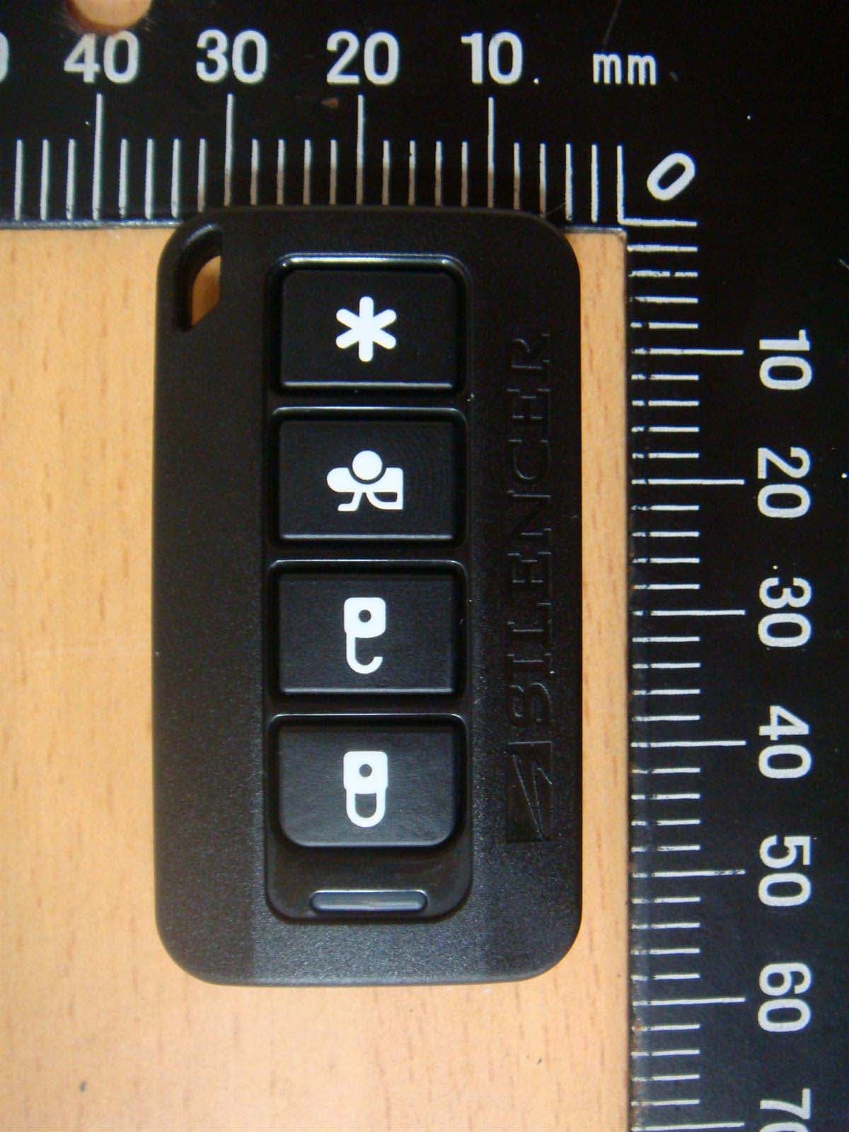
Other Applications from Advance Security Inc
H5OT62
Dec 11, 2015Remote Control
Equipment Class
DSC - Part 15 Security/Remote Control Transmitter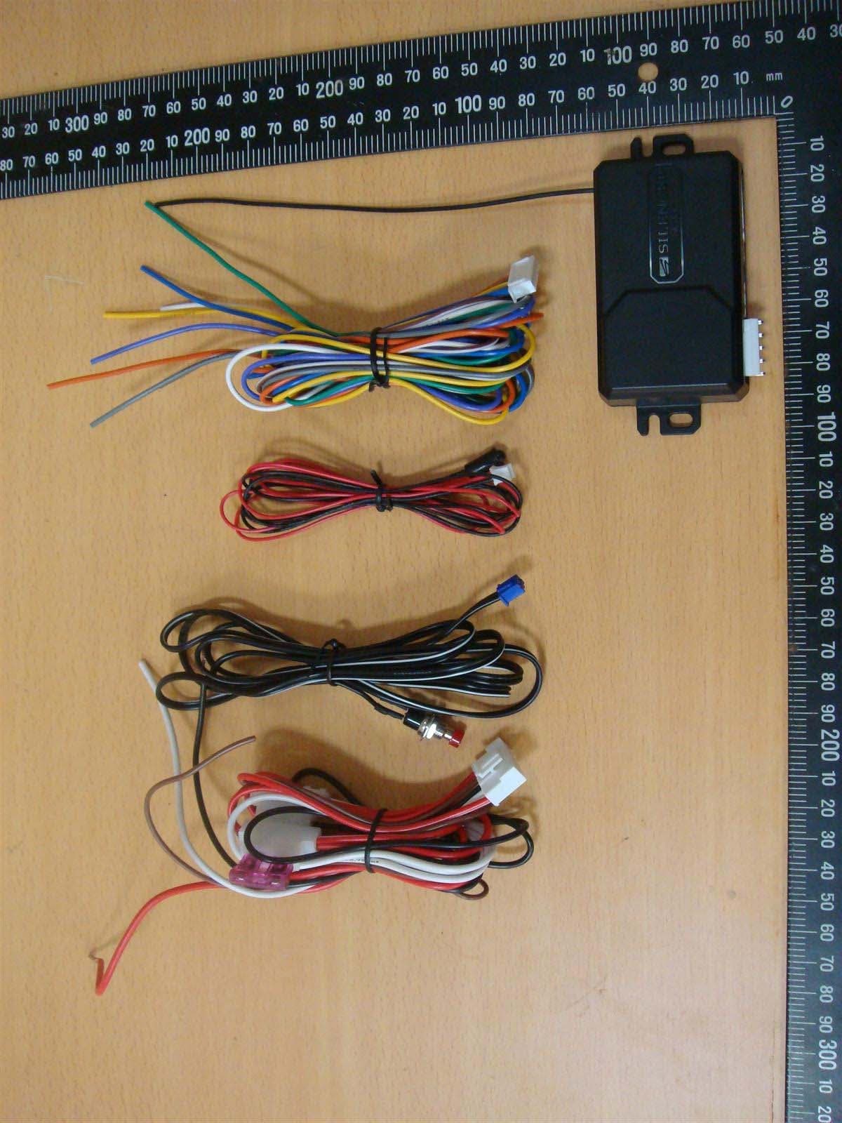
H5OR57
Dec 11, 2015Remote Control
Equipment Class
CYY - Communications Receiver used w/Pt 15 Transmitter
H5OTR64
Oct 22, 2015Remote Control
Equipment Class
DSS - Part 15 Spread Spectrum Transmitter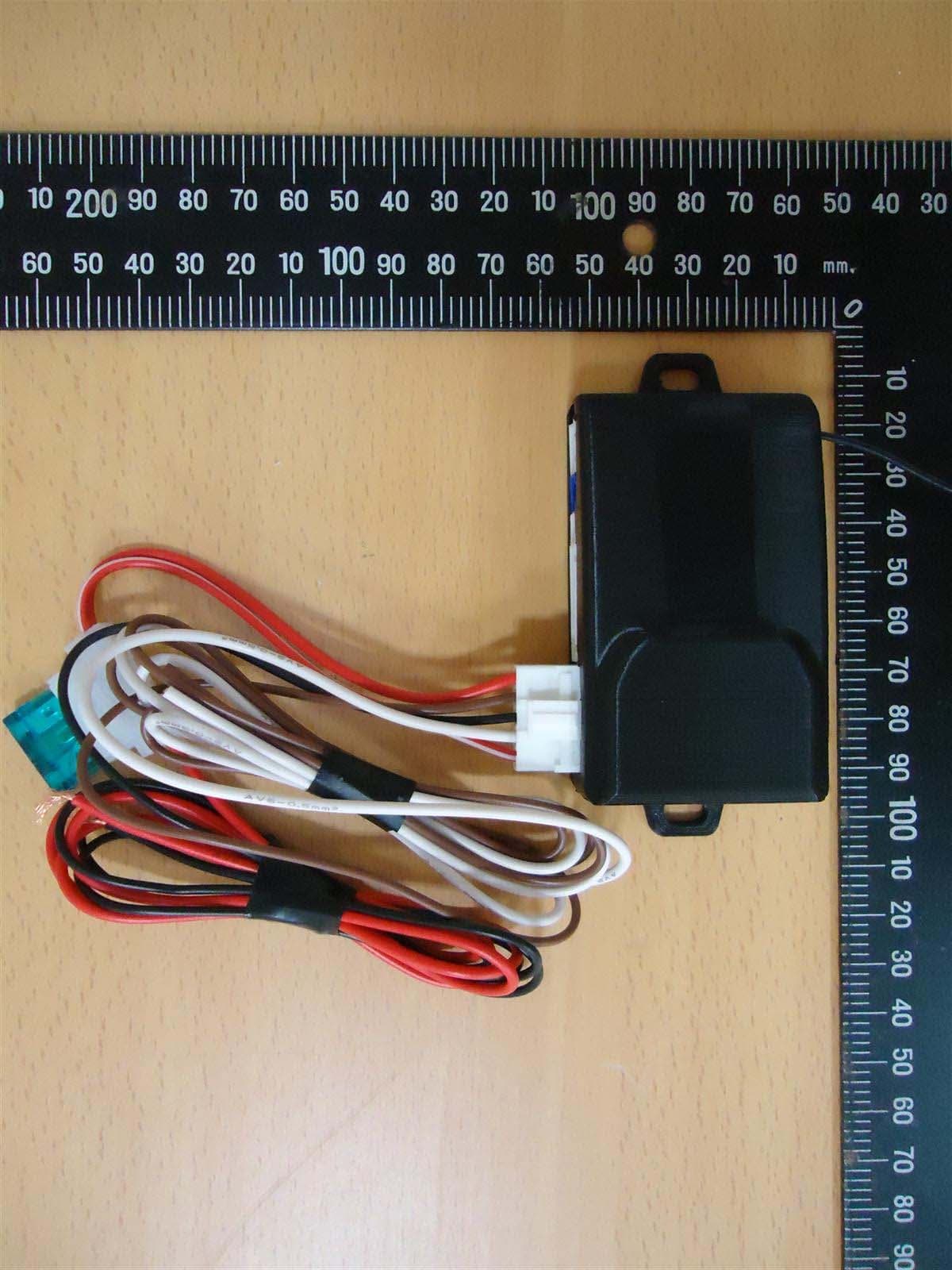
H5OR56
Sep 10, 2015Remote Control
Equipment Class
CYY - Communications Receiver used w/Pt 15 Transmitter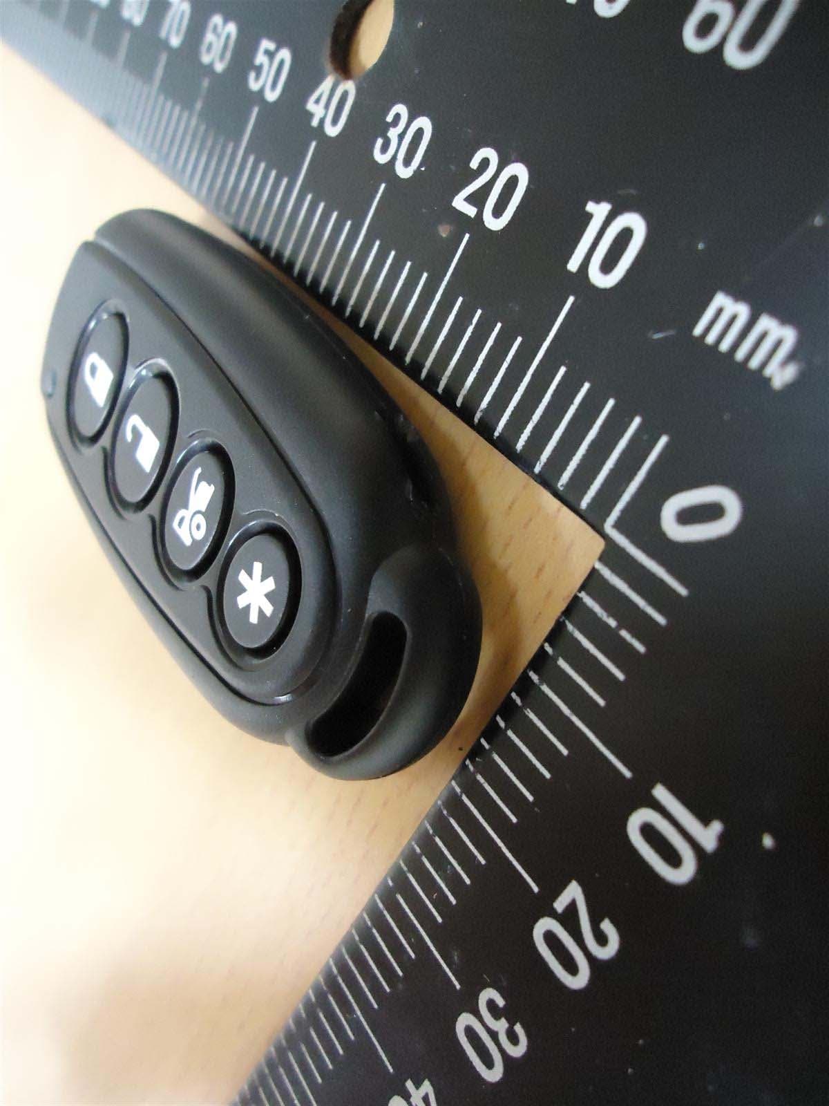
H5OT61
Sep 07, 2015Remote Control
Equipment Class
DSC - Part 15 Security/Remote Control Transmitter