H5OTR45Car Alarm Transceiver
Advance Security Inc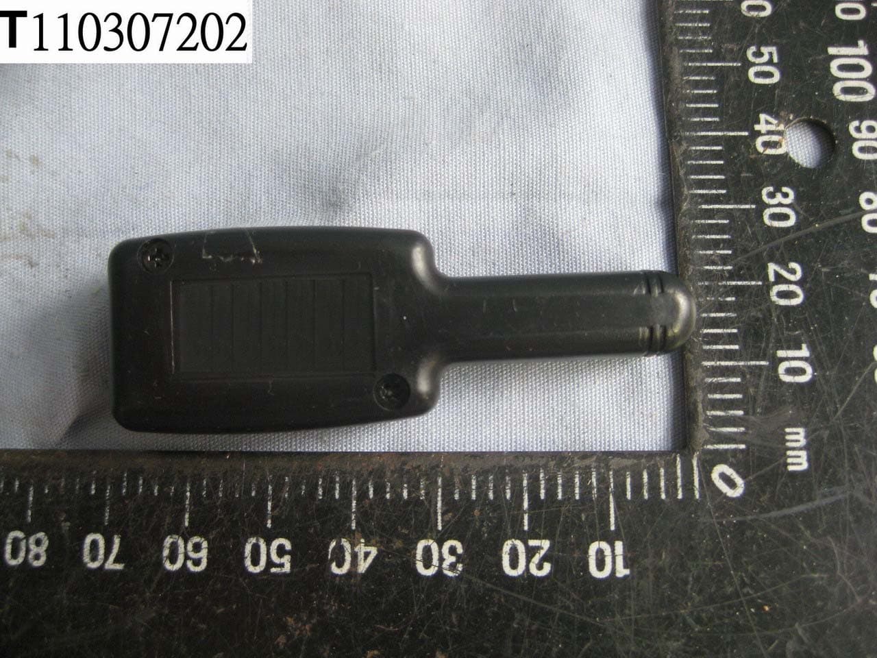
Click to zoom
Application Details
- Equipment Class
- DSR - Part 15 Remote Control/Security Device Transceiver
- Date of Grant
- Jun 12, 2011
- Application Purpose
- Original Equipment
- Date of Application
- Jun 12, 2011
- Equipment Note
- Car Alarm Transceiver
- Frequency Range
- 433.92000000 - 433.92000000
- Company
- Advance Security Inc
- Country
- Taiwan
Documents & Files
Document Text
Text extracted from the exhibit documents filed with the FCC. Open a document above to read the original.
Users Manual
Pin # Wire Color Specification 1 White (-) Dome Light Output 2 Gray Channel 3Trunk Output (-) 3 White / Blue Channel 4 (-) Aux Output 4 Pink 2 Step Unlock Output 5 Orange Ground Output (-) when armed 6 Green Negative (-) Door Trigger 7 Yellow Ignition: 12 Volt (+) with key ON 8 Violet Positive (+) Door Trigger 9 Black / Blue Channel 5 Programmable Output (-) 10 Blue Zone 2, (-) Hood / Trunk Trigger 1. Blue Wire 3. Green Wire ( - ) Lock Pulse ( + ) Unlock Pulse( - ) Unlock Pulse ( + ) Lock Pulse 4. Green Wire / Warn Away Input 3. Blue Wire / Zone 4 Ground Trigger 2. Black Wire / Negative 1 . Red Wire / +12Volts 22 - Pin Connector 5 PIN MAIN POWER HARNESS Door Lock Connector QUICK START INSTALLATION GUIDE If you are not proficient in the in stallation of this product or would like a full version of the installation manual, FOR PROFESSIONAL INSTALLATION ONLY! WHITE: PARKING LIGHT OUTPUT BLACK : MAIN SYSTEMS GROUND BROWN : POSITIVE SIREN OUTPUT RED : FUSED 12 VOLT (+) BATTERY BLUE / BLACK: (-) HORN OUTPUT TRANSMITTER PROGRAMMING: Note: This mode will only retain the last 4 remote transmitters programmed. If the transmitter memory is exceeded, th e security system will start deleting transmitters from memory in chronological order. 1. Turn the Ignition 'switch ‘ OFF/ON’ 4 TIMES and stay in ON position . “Within 15 seconds”. 2. Push the Valet switch 4 times and hold it on the 4th push until a long chirp is heard. Then release the valet switch. You are now in the Transmitter programming mode. 3. Press and hold any button of the tran smitter until the siren responds with a confirming chirp, indicating the si gnal has been stored into memory. 4. If you have additional transmitters (up to 4) that need to be programmed, repeat step 3 for each transmitter. Exit: Turn Ignition to 'OFF' position, or l eave it for 15 seconds. 3 long chirps & 3 parking light flashes will confirm exit. 10 Pin, Main Connector Shock Sensor Harness 4-PIN BLACK CONNECTOR: ANTENNA MODULE The transmitting/antenna mounting location should be the upper left or lower left corner of driver’s windshield. For optimum range we suggest that the antenna be mounted as shown in picture to the right. (Antenna tip facing up) Warning! Do not mount in such a manner that it obstructs the driver’s view. -Paging button used to page person in possession of the 2-Way transmitter. - Remove the protective tape backing. - Carefully align the two-way transceiver/antenna and apply to windshield. - Route the black connector wire behind the trim and connect to the two-way transceiver/antenna. - Connect the other end to the control module. ** Special considerations must be made for windshield glass as some newer vehicles utilize a metal-shielded window glass that will inhibit or restrict RF reception. In these vehicles, route th e two ways transceiver/antenna module away from metallic shielded window glass as far as possible.** 2 STEP DOOR UNLOCK WIRE CONNECTION FOR 5 WIRE ALTERNATING DOOR LOCKS +12V Cut the Existing Lock Wire Cut Existing Unlock X Cut the Unlock Wire Lock Unlock OEM Door Master Lock OEM SlaveDoor LockSwitch +12V Lock Unlock To All OtherDoor LockMotors H2/13 : 22-Pin Plug From Alarm White/Green Wire x X Blue Wire OEM Driver’s Door Lock Motor + 12V 85 86 87 87a 30 30 87 85 87a 86 30 87 85 87a 86 Green Wire H9 : 3 Pin Plug To Alarm Red +12V 2 STEP DOOR UNLOCK WIRE CONNECTION FOR 5 WIRE ALTERNATING DOOR LOCKS +12V Cut the Existing Lock Wire Cut Existing Unlock X Cut the Unlock Wire Lock Unlock OEM Door Master Lock OEM SlaveDoor LockSwitch +12V Lock Unlock To All OtherDoor LockMotors H2/13 : 22-Pin Plug From Alarm White/GreenWire x X Blue Wire OEM Driver’s Door Lock Motor + 12V 85 86 87 87a 30 30 87 85 87a 86 30 87 85 87a 86 Green Wire H9 : 3 Pin Plug To Alarm Red +12V FEATURE “B” PROGRAMMING: Turn the Ignition switch ‘ON/OFF’ 3 TIMES and stay in OFF position . Push the Valet switch 4 times (holding in on the 4 th push ) until one long chirp is heard then release the valet switch. You are now in the Alarm feature “B” programming mode. Press and release the transmitter butt on corresponding to the feature you want to program. FEATURE “C” PROGRAMMING: 1 Turn the Ignition 'switch ‘ON/OFF’ 3 TIMES and stay in OFF position . 2 Push the Valet switch 5 times (holding in on the 5th push ) until one long chirp is heard then release the valet switch. Y ou are now in the Alarm feature “C” programming mode. 3 Press and release the transmitter button corresponding to the feature you want to program. FEATURE “A” PROGRAMMING: 1. Turn the Ignition 'switch ‘ON/OFF’ 3 TIMES and stay in OFF position . 2. Push the Valet switch 3 times (holding in on the 3rd push ) until one long chirp is heard. Then release the valet switch. You are now in the Alarm feature “A” programming mode. 3. Press and release the transmitte r button corresponding to the feature you want to program. a. The siren chirps and LED pause will indicate previously setting. b. The factory default settings is always [1] LED flash, [1] chirp. 4 Depress the transmitter button to c hange the feature. Simply keep re- depressing the transmitter button unt il the system advances to your desired setting. Press the transmitter button correspon ding to the feature you want to program. Press Transmitt er Button One Chirp / LED one pulse Factory Default Setting Two Chirps / LED two pulses Three Chirps / LED three pulses Four Chirps / LED four pulses 1 All Confirmation chirps on Siren Confirmation chirp on only Horn Confirmation chirp on only All Confirmation chirps off 2 Automatic Rearm off Automatic Rearm on 3 Instant Door Ajar error chirp 45 seconds delay Door Ajar error chirp. 4 + Without Car- jack mode Active Car-jack mode Passive Car-jack mode Exit: Turn Ignition to 'ON' position, or leave it for 15 seconds. 3 long chirps & 3 parking light flashes will confirm exit. Channel 2/3/4 Timer Control Output Programming: Enter: 1. Turn the Ignition 'switch ‘ON/OFF’ 5 TIMES and stay in OFF position. 2. Push the …
Text truncated - open the document above for the full version.
External Photos
Compliance Certification Services Inc. Report No.: T110307202 Date of Issue: June 9, 2011 A1-1 Total Page: 2 Rev. 00 APPENDIX 1 - PHOTOGRAPHS OF EUT
ID Label/Location Info
FCC ID LABEL FORMAT AND LOCATION Applicant: Advance Security Inc. Model: TX103 FCC ID: H5OTR45 FCC ID: H5OTR45 FCC ID LABEL AREA
Internal Photos
Compliance Certification Services Inc. Report No.: T110307202 Date of Issue: June 9, 2011 A1-2 Rev. 00
Test Report
Compliance Certification Services Inc. Report No.: T110307202-RP1 FCC ID: H5OTR45 Date of Issue: June 9, 2011 Note: This report shall not be reproduced except in full, without the written approval of Compliance Certification Services Inc. This document may be altered or revised by Compliance Certification Services Inc. personnel only, and shall be noted in the revision section of the document. Page 1 Total Page: 29 Rev. 00 FCC 47 CFR PART 15 SUBPART C TEST REPORT For Car Alarm Transceiver Model: TX103 Brand Name: Advance Security Inc. Issued to Advance Security Inc. 3F, 48 Ta An Street, Hsi Chih, Taipei Hsien, TAIWAN R.O.C. Issued by Compliance Certification Services Inc. Sindian Lab. No.163-1, Jhongsheng Rd, Sindian City, Taipei County 23151, Taiwan (R.O.C.) TEL: (02) 2217-0894 FAX: (02) 2217-1029 Compliance Certification Services Inc. Report No.: T110307202-RP1 FCC ID: H5OTR45 Date of Issue: June 9, 2011 Page 2 Rev. 00 TABLE OF CONTENTS 1. TEST RESULT CERTIFICATION............................................................................................. 3 2. EUT DESCRIPTION .................................................................................................................... 4 3. TEST METHODOLOGY ............................................................................................................. 5 3.1 EUT CONFIGURATION.............................................................................................................. 5 3.2 EUT EXERCISE......................................................................................................................... 5 3.3 GENERAL TEST PROCEDURES.................................................................................................. 5 3.4 FCC PART 15.205 RESTRICTED BANDS OF OPERATIONS ............................................. 6 3.5 DESCRIPTION OF TEST MODES................................................................................................. 6 4. INSTRUMENT CALIBRATION................................................................................................. 7 4.1 MEASURING INSTRUMENT CALIBRATION........................................................................... 7 4.2 MEASUREMENT EQUIPMENT USED .............................................................................. 7 5. FACILITIES AND ACCREDITATIONS ................................................................................... 8 5.1 FACILITIES.............................................................................................................................. 8 5.2 EQUIPMENT............................................................................................................................. 8 5.3 TABLE OF ACCREDITATIONS AND LISTINGS............................................................................ 9 6. SETUP OF EQUIPMENT UNDER TEST .................................................................................. 9 6.1 SETUP CONFIGURATION OF EUT.............................................................................................. 9 6.2 SUPPORT EQUIPMENT.............................................................................................................. 9 7. FCC PART 15.231 REQUIREMENTS...................................................................................... 10 7.1 20DB BANDWIDTH ........................................................................................................... 10 7.2 LIMIT OF TRANSMISSION TIME.............................................................................................. 12 7.3 DUTY CYCLE CORRECTION FACTOR.......................................................................... 14 7.4 RADIATED EMISSIONS........................................................................................................... 18 7.5 POWERLINE CONDUCTED EMISSIONS.................................................................................... 25 APPENDIX I PHOTOGRAPHS OF TEST SETUP ....................................................................... 26 Compliance Certification Services Inc. Report No.: T110307202-RP1 FCC ID: H5OTR45 Date of Issue: June 9, 2011 Page 3 Rev. 00 1. TEST RESULT CERTIFICATION Applicant: Advance Security Inc. 3F, 48 Ta An Street, Hsi Chih, Taipei Hsien, TAIWAN R.O.C. Equipment Under Test: Car Alarm Transceiver Brand Name: Advance Security Inc. Model: TX103 Date of Test: April 12, 2011 ~ June 4, 2011 APPLICABLE STANDARDS STANDARD TEST RESULT FCC 47 CFR Part 15 Subpart C No non-compliance noted We hereby certify that: The above equipment was tested by Compliance Certification Services Inc. Sindian Lab. The test data, data evaluation, test procedures, and equipment configurations shown in this report were made in accordance with the procedures given in ANSI C63.4: 2003 and the energy emitted by the sample EUT tested as described in this report is in compliance with conducted and radiated emission limits of FCC Rules Part 15.207, 15.209 and Part 15.231. The test results of this report relate only to the tested sample identified in this report. Compliance Certification Services Inc. Report No.: T110307202-RP1 FCC ID: H5OTR45 Date of Issue: June 9, 2011 Page 4 Rev. 00 2. EUT DESCRIPTION Product Car Alarm Transceiver Brand Name Advance Security Inc. Model Number TX103 Modulation Technique ASK Power Supply 12VDC from Power Supply Frequency Range 433.92 MHz Antenna Specification Helical Antenna / Gain: -2dbi Associated Receiver H5OT51 Remark: 1. The sample selected for test was production product and was provided by manufacturer. 2. This submittal(s) (test report) is intended for FCC ID: H5OTR45 filing to comply with Section 15.207, 15.209 and 15.231 of the FCC Part 15, Subpart C Rules. Compliance Certification Services Inc. Report No.: T110307202-RP1 FCC ID: H5OTR45 Date of Issue: June 9, 2011 Page 5 Rev. 00 3. TEST METHODOLOGY The tests documented in this report were performed in accordance with ANSI C63.4 (2003…
Text truncated - open the document above for the full version.
Test Setup Photos
Compliance Certification Services Inc. Report No.: T110307202-RP1 FCC ID: H5OTR45 Date of Issue: June 9, 2011 Page 26 Rev. 00 APPENDIX I - PHOTOGRAPHS OF TEST SETUP RADIATED EMISSION SET UP PHOTOS TX MODE X axis Compliance Certification Services Inc. Report No.: T110307202-RP1 FCC ID: H5OTR45 Date of Issue: June 9, 2011 Page 27 Rev. 00 Y axis Compliance Certification Services Inc. Report No.: T110307202-RP1 FCC ID: H5OTR45 Date of Issue: June 9, 2011 Page 28 Rev. 00 Z axis Compliance Certification Services Inc. Report No.: T110307202-RP1 FCC ID: H5OTR45 Date of Issue: June 9, 2011 Page 29 Rev. 00 RX MODE
Contact Information
Applicant
Michael Chen(SAL)
Test Firm
Compliance Certification Services Inc.Rick Yeo
Technical Specifications
| # | Rule Parts | Frequency Range | Power Output |
|---|---|---|---|
| 1 | 15.231 | 433.92 MHz - 433.92 MHz | - |
Other Applications from Advance Security Inc
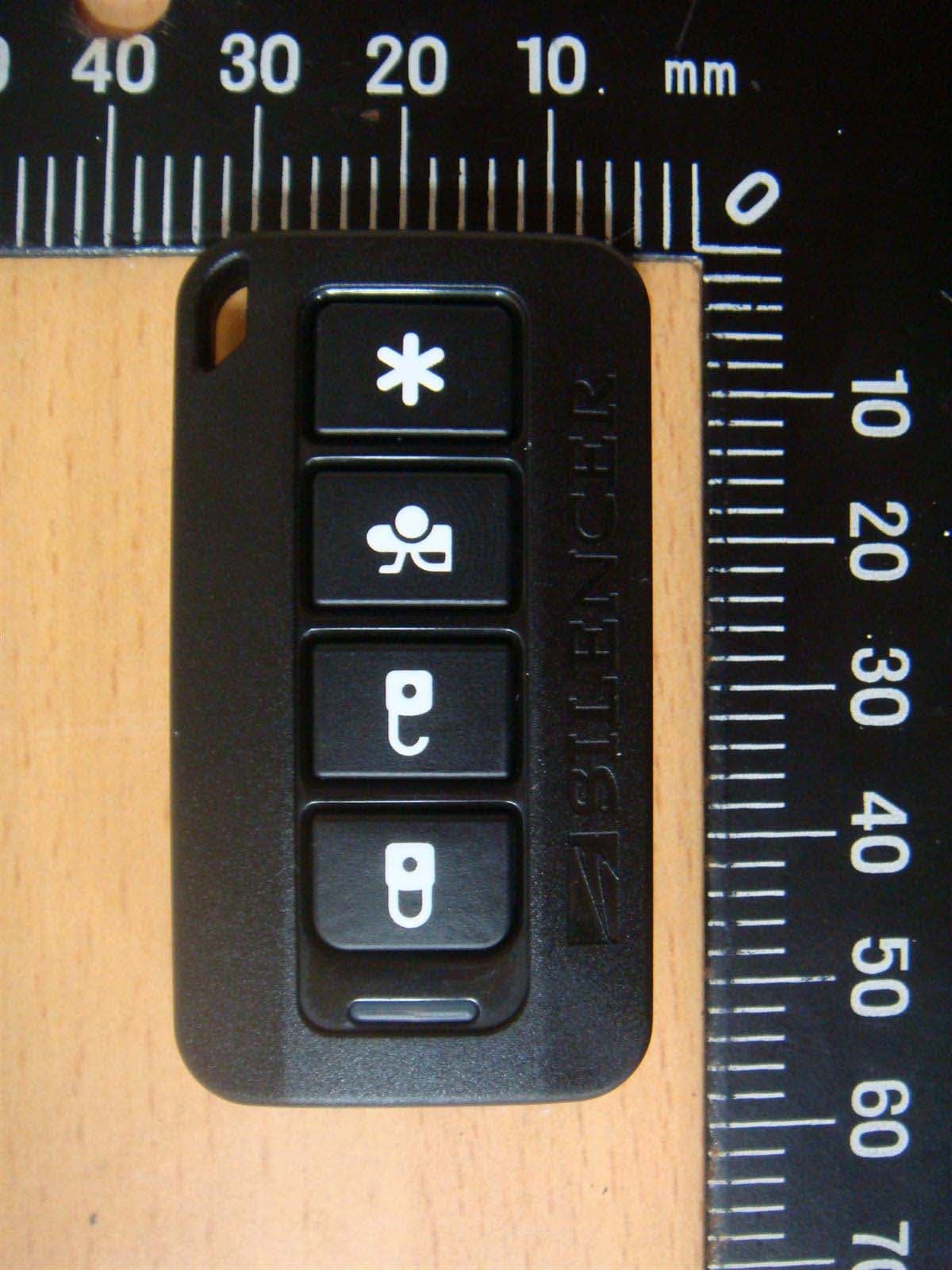
H5OT62
Dec 11, 2015Remote Control
Equipment Class
DSC - Part 15 Security/Remote Control Transmitter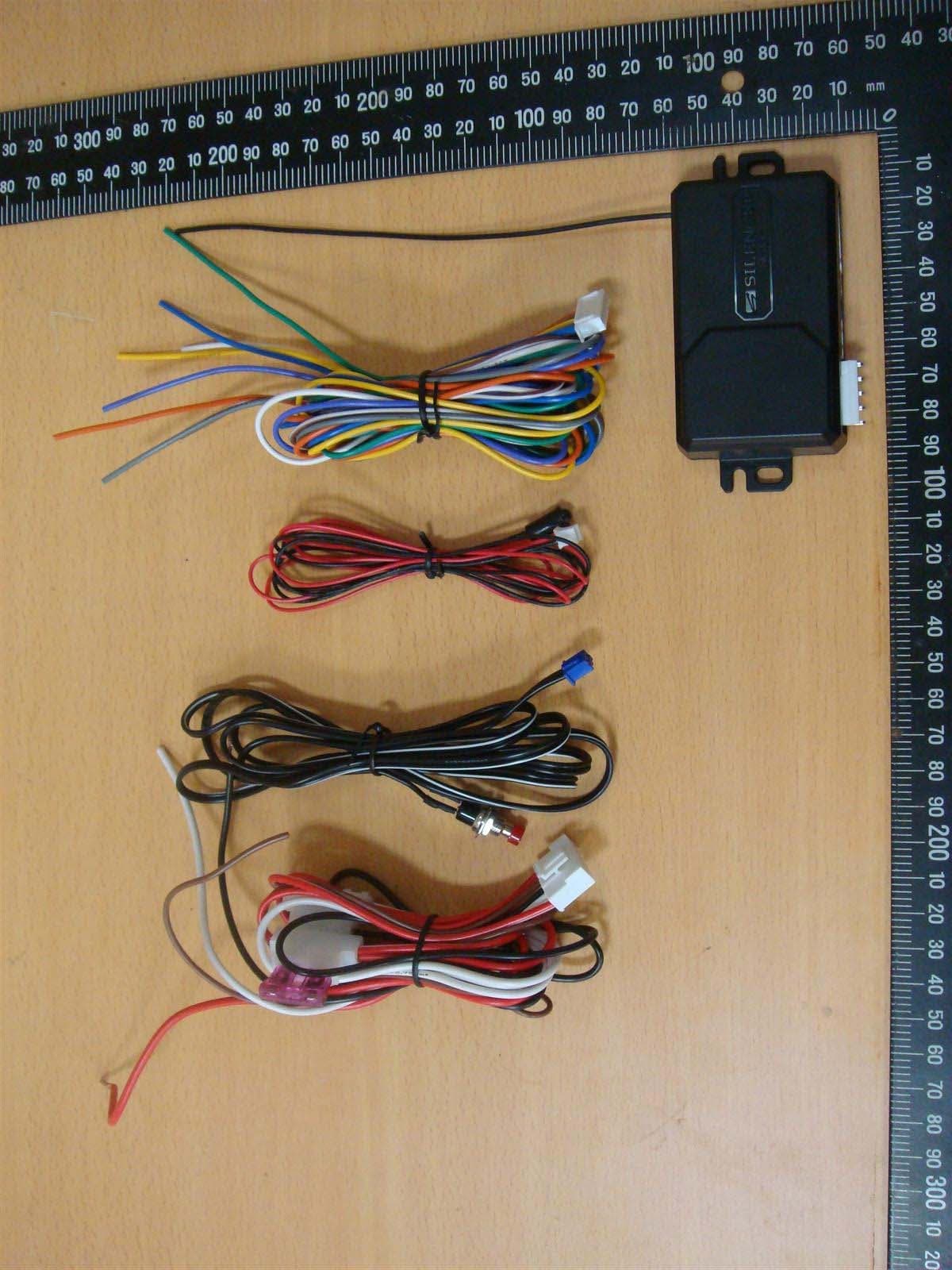
H5OR57
Dec 11, 2015Remote Control
Equipment Class
CYY - Communications Receiver used w/Pt 15 Transmitter
H5OTR64
Oct 22, 2015Remote Control
Equipment Class
DSS - Part 15 Spread Spectrum Transmitter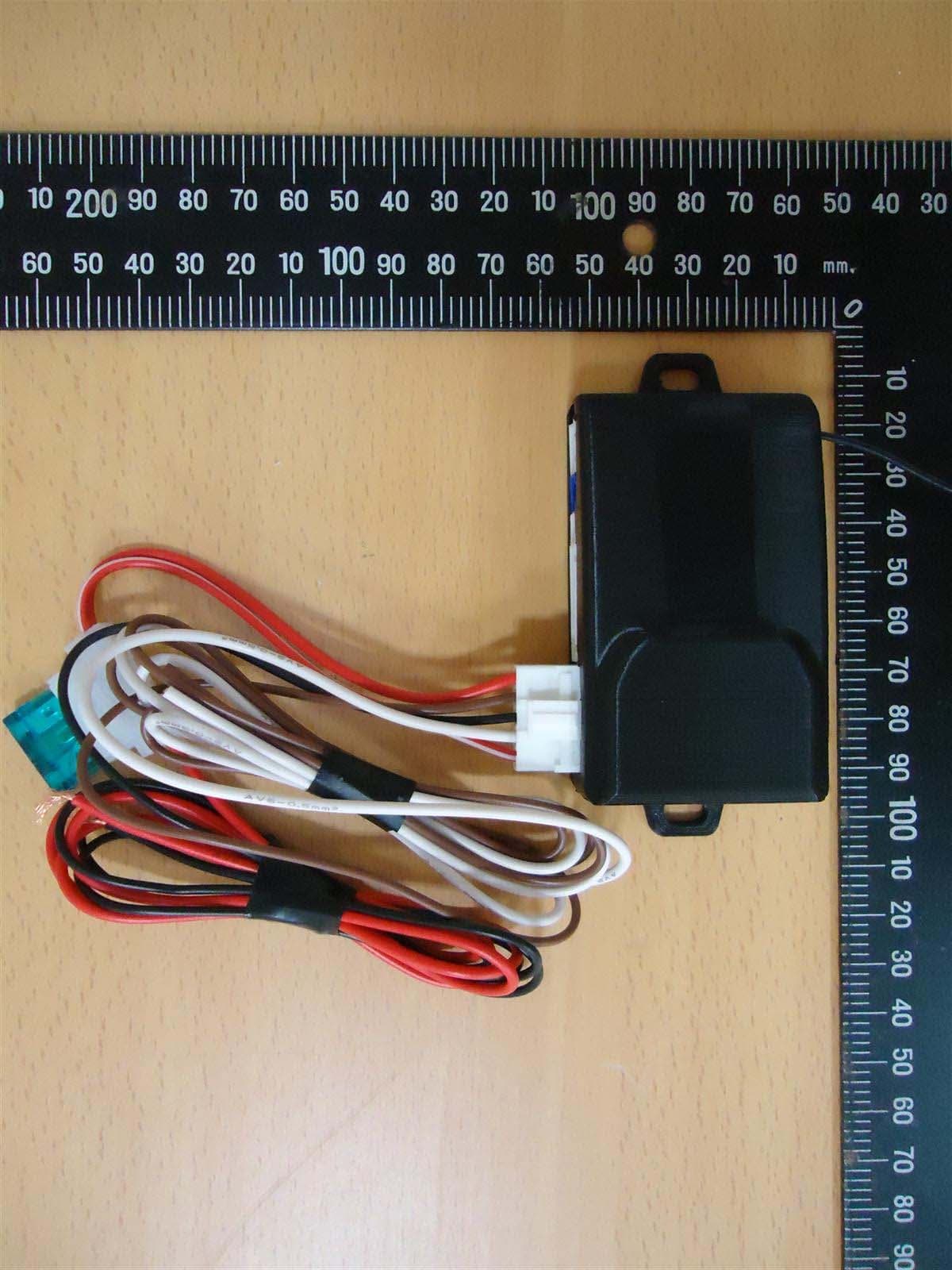
H5OR56
Sep 10, 2015Remote Control
Equipment Class
CYY - Communications Receiver used w/Pt 15 Transmitter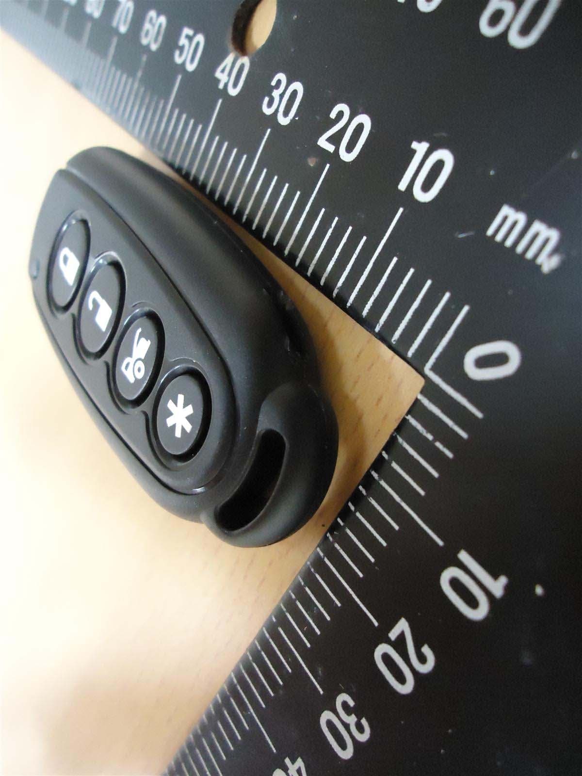
H5OT61
Sep 07, 2015Remote Control
Equipment Class
DSC - Part 15 Security/Remote Control Transmitter